As urban environments evolve into data-driven ecosystems, the demand for massive bandwidth and millisecond latency has moved from a luxury to a necessity. The fiber backbone is the invisible infrastructure that bridges the gap between digital vision and urban reality, providing the essential connectivity for millions of sensors, vehicles, and citizens.
The Anatomy of a Smart City Fiber Backbone
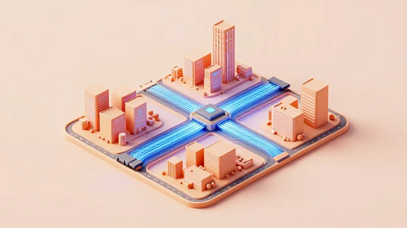
Defining the Smart City Fiber Backbone
A smart city fiber backbone is the foundational layer of urban telecommunications, acting as the ultra-high-speed expressway that transports massive volumes of data between a city's central core and its peripheral access nodes. Unlike local last-mile connections, the backbone is engineered for extreme reliability, low latency, and massive bandwidth to support the concurrent demands of IoT sensors, public Wi-Fi, emergency services, and autonomous traffic management systems. It functions as the central nervous system of a municipality, ensuring that data generated at the edge can reach processing centers or cloud environments with minimal delay.
The Hierarchical Role of the Backbone Layer
In the context of network topology, the backbone sits between the core network and the distribution or access layers. Its primary responsibility is aggregation: taking smaller data streams from neighborhood-level hubs and consolidating them into a high-throughput pipe. This architectural positioning ensures that localized outages or congestion do not degrade the performance of the city-wide network.
| Feature | Backbone Layer | Access Layer (Last Mile) |
|---|---|---|
| Capacity | Terabits per second (Tbps) | Megabits to Gigabits per second (Mbps/Gbps) |
| Topology | Ring or Mesh (High Redundancy) | Star or Point-to-Multipoint |
| Fiber Type | High-count Single Mode (SMF) | Lower-count Single Mode or PON |
| Typical Reach | City-wide (10km - 100km+) | Localized (< 5km) |
Common Architectural Questions
- Why is redundancy critical in a smart city backbone?
Because the backbone carries data for critical infrastructure like power grids and emergency response, any failure can lead to catastrophic city-wide service loss. Redundant paths, often in a self-healing ring topology, ensure traffic is rerouted instantly if a cable is severed. - What technologies are used to increase backbone capacity?
Dense Wavelength Division Multiplexing (DWDM) is the standard technology used to maximize fiber efficiency. It allows multiple data signals to be sent over different wavelengths of light on a single fiber strand, effectively multiplying the capacity of existing glass without digging new trenches. - How does the backbone interface with localized nodes?
The backbone connects to 'Meet-Me Rooms' or central offices where OLT (Optical Line Terminals) and high-end routers aggregate data from the surrounding district before pushing it into the high-speed core.
By utilizing high-count fiber cables—often containing 864 to 1728 strands or more—modern smart city backbones are built with substantial dark fiber reserves. This future-proofs the city, allowing for the rapid deployment of new 5G small cells and edge computing facilities without the need for additional invasive construction.
Technical Standards: Single-Mode vs. Multi-Mode in Urban Scale
Technical Standards: Single-Mode vs. Multi-Mode in Urban Scale
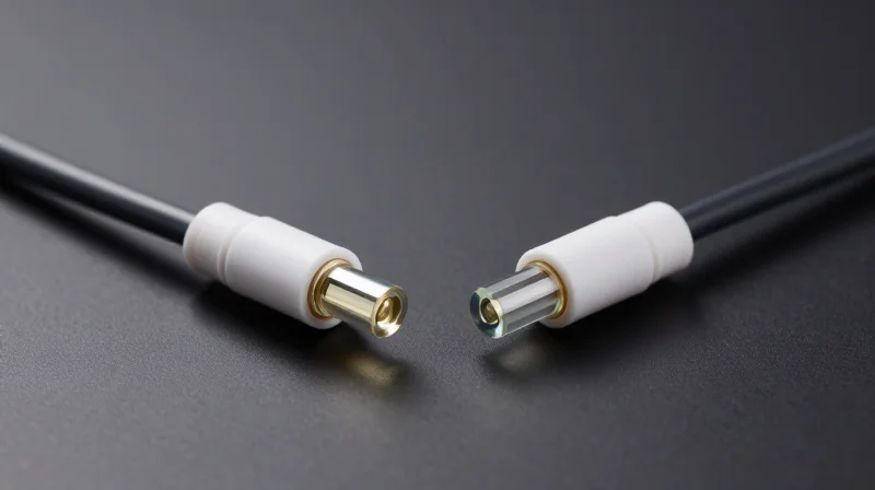
In the architectural design of a smart city fiber backbone, OS2 single-mode fiber (SMF) serves as the industry benchmark because it effectively eliminates the physical distance limitations that restrict multi-mode fiber (MMF) to localized campus environments. While multi-mode fiber is efficient for short-reach data center interconnects, the geographical footprint of a metropolitan area network (MAN) demands the low-attenuation and high-bandwidth-distance product only provided by a single-mode core.
OS2 Single-Mode: The Foundation of Long-Haul Reach
OS2 single-mode fiber is optimized for wavelengths of 1310 nm and 1550 nm, featuring a narrow core of approximately 9 micrometers. This design allows only a single mode of light to propagate, which entirely avoids modal dispersion—the primary factor that degrades signal quality in multi-mode cables. For a smart city backbone, this translates to the ability to transmit 100Gbps or even 400Gbps signals across 40 to 80 kilometers without the need for expensive signal regeneration or intermediate amplification.
| Parameter | OS2 Single-Mode (SMF) | OM4/OM5 Multi-Mode (MMF) |
|---|---|---|
| Core Diameter | 9 µm | 50 µm |
| Max Transmission Distance | Up to 100 km (standard-dependent) | Typically < 550 meters |
| Signal Loss (Attenuation) | ~0.4 dB/km at 1310 nm | ~3.0 dB/km at 850 nm |
| Primary Use Case | City-wide backbone & WAN | Intra-building LAN & Data Centers |
The Multi-Mode Limitation in Metropolitan Environments
Multi-mode fiber standards such as OM4 and OM5 utilize a larger 50-micrometer core designed for use with cheaper Vertical-Cavity Surface-Emitting Lasers (VCSELs). However, as light pulses travel through the wider core, they take multiple paths (modes) of slightly different lengths, causing the pulses to spread out and eventually overlap. This phenomenon, known as modal dispersion, restricts 10G and 40G transmissions to a few hundred meters, making it technically impossible to serve as a primary link between distant smart city nodes like traffic management centers and municipal data hubs.
- Can OM5 support Smart City applications?
Only in localized 'Edge' environments. While OM5 supports Shortwave Wavelength Division Multiplexing (SWDM), its reach is still limited to roughly 440 meters for 40/100G speeds, which is insufficient for a city-scale backbone. - Why is OS2 preferred over OS1 for the backbone?
OS2 is a 'low water peak' fiber designed for outdoor, long-distance deployments with a lower attenuation rate (0.4 dB/km) compared to the 1.0 dB/km rate of the indoor-rated OS1 standard. - Is single-mode fiber more expensive to deploy?
While single-mode transceivers (optics) are historically more expensive than multi-mode optics, the fiber cable itself is often cheaper. At the scale of a smart city, the cost savings on reduced infrastructure (fewer repeaters) far outweigh the higher cost of transceivers.
Optical Multiplexing: Increasing Capacity with WDM and DWDM

Scaling Capacity through Wave Division Multiplexing (WDM)
Optical multiplexing is the foundational technology that allows smart city planners to future-proof fiber backbones without the prohibitive cost of laying additional physical cables. By utilizing Wave Division Multiplexing (WDM), network operators can transmit multiple data streams concurrently over a single strand of fiber by assigning each stream a unique wavelength, or 'color,' of light. This effectively transforms a single fiber pair into a high-capacity multi-lane highway, where distinct services—such as municipal public Wi-Fi, real-time traffic sensor data, and high-definition public safety video feeds—can coexist on the same infrastructure without signal interference.
Comparing CWDM and DWDM Architectures
While the core principle of multiplexing remains consistent, the technical execution differs between Coarse Wave Division Multiplexing (CWDM) and Dense Wave Division Multiplexing (DWDM). The choice between these two architectures is dictated by the required channel density, the total distance of the urban link, and the long-term scalability requirements of the smart city's digital infrastructure.
| Feature | CWDM (Coarse) | DWDM (Dense) |
|---|---|---|
| Channel Spacing | 20 nm (Wide) | 0.8 nm or less (Narrow) |
| Capacity | Up to 18 channels | Up to 80+ channels |
| Distance Range | Short to Medium (up to 80km) | Long-haul (thousands of km) |
| Amplification | Passive (Typically unamplified) | Active (EDFA support) |
| Urban Application | District-level connectivity | City-wide core backbone |
The Strategic Value of DWDM in Smart Cities
DWDM is the gold standard for the core backbone of a smart city because it supports incredibly high-density data transmission. By packing channels closer together in the C-band and L-band spectrums, DWDM leverages optical amplifiers like Erbium-Doped Fiber Amplifiers (EDFAs) to boost signals over vast distances without requiring frequent O-E-O (Optical-to-Electrical-to-Optical) conversions. This is critical for connecting disparate city districts or regional data centers, ensuring that the backbone can handle the exponential growth of IoT device density as a city evolves from basic connectivity to advanced autonomous systems.
Multiplexing FAQs
- Why is multiplexing preferred over laying more physical fiber?
The majority of fiber deployment costs—often exceeding 80%—are tied to civil works like trenching, labor, and permitting. Multiplexing allows cities to increase capacity by orders of magnitude using existing 'dark fiber' assets, providing a much higher return on investment. - Is DWDM compatible with standard single-mode fiber?
Yes, DWDM is specifically optimized for OS2 single-mode fiber. It utilizes the low-loss regions of the fiber's spectrum to ensure maximum signal integrity over long urban reaches. - What is the role of a ROADM in these networks?
A Reconfigurable Optical Add-Drop Multiplexer (ROADM) allows network administrators to manage wavelengths via software. This means they can add or drop data capacity at specific city nodes remotely without needing to dispatch technicians to change physical hardware.
Architecture Models: Ring, Mesh, and Star Topologies
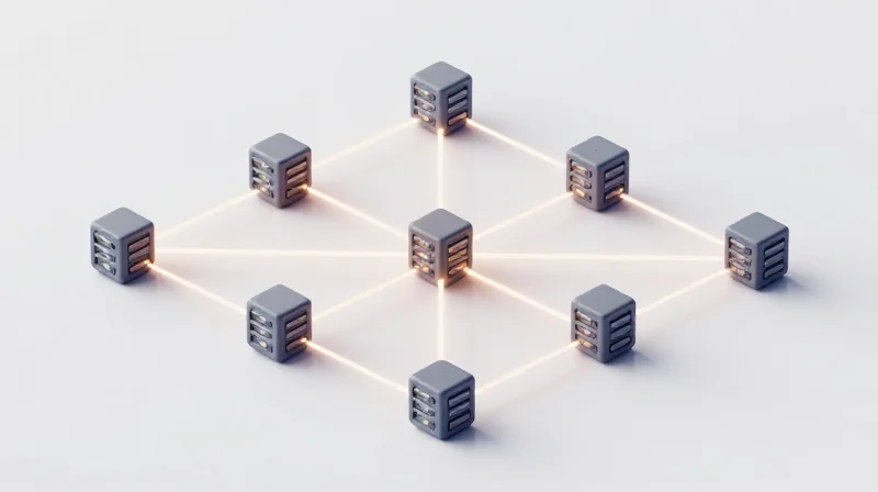
The architectural layout of a smart city fiber backbone determines its ability to withstand physical cable cuts and hardware failures while maintaining continuous service for critical urban systems. Selecting the appropriate topology—Ring, Mesh, or Star—requires a technical trade-off between deployment costs, ease of management, and the specific redundancy needs of services like public safety and autonomous traffic control.
The Ring Topology: Self-Healing Reliability
Ring topologies are the standard for most metropolitan backbones due to their inherent 'self-healing' capabilities. By connecting nodes in a closed loop, data can travel in two directions. If a fiber strand is severed at one point, Ethernet Ring Protection Switching (ERPS) protocols, such as ITU-T G.8032, automatically reroute traffic in the opposite direction, often within less than 50 milliseconds.
The Mesh Topology: Maximum Redundancy
In a mesh architecture, nodes are interconnected with multiple redundant paths. A full mesh offers the highest level of fault tolerance, as every node is connected to every other node, though this is rarely feasible at a city-wide scale due to the massive amount of cabling required. Most smart cities utilize a partial mesh for core backbone segments where mission-critical data must remain accessible even if multiple nodes or links fail simultaneously.
The Star Topology: Centralized Efficiency
A star topology features a central hub—usually a primary data center or CO (Central Office)—with individual fiber links radiating out to edge nodes. While this is the simplest to manage and least expensive to cable, it introduces a significant single point of failure at the hub and provides no path redundancy for the edge nodes. It is typically reserved for non-critical edge applications rather than the core backbone.
Comparative Analysis of Backbone Architectures
| Feature | Ring Topology | Mesh Topology | Star Topology |
|---|---|---|---|
| Redundancy | High (Single failure) | Very High (Multiple failures) | Low (No path redundancy) |
| Deployment Cost | Moderate | Extremely High | Low |
| Complexity | Moderate | High | Low |
| Self-Healing | Yes (G.8032/ERPS) | Yes (Dynamic Routing) | No |
Frequently Asked Questions on Network Topology
- Why is Ring topology favored over Mesh in city budgets?
Ring topologies offer a 'sweet spot' of high reliability and lower fiber-mileage costs. A ring provides sufficient redundancy for most urban needs without the geometric cost increase of interconnecting every node as required by mesh. - Can different topologies be combined?
Yes, most modern smart cities use a 'Hybrid' approach. They may utilize a mesh for the high-capacity core, rings for the distribution layers, and star configurations for the final access points (the edge). - What happens if both sides of a ring are cut?
A dual-failure in a standard ring will result in a network partition, isolating nodes. This is why critical core segments often employ dual-rings or partial mesh for added insurance.
Supporting the 5G Revolution: Fiber as the Backhaul
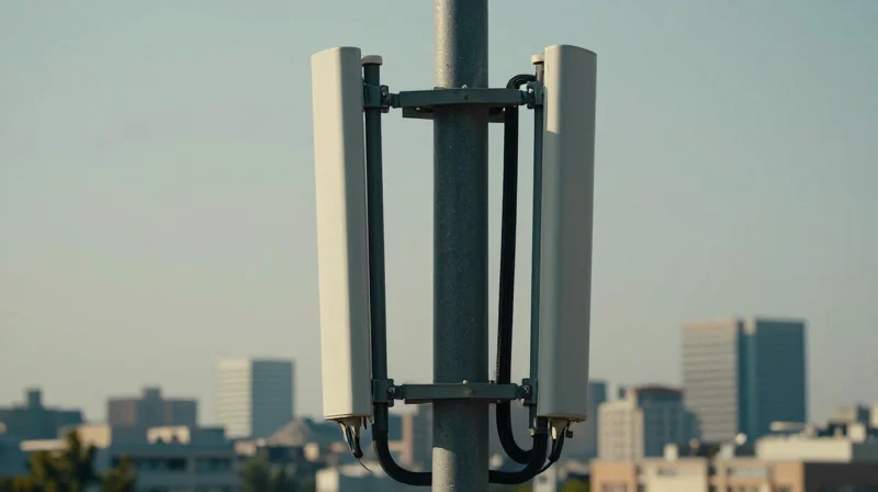
The 5G revolution is often described as a wireless phenomenon, but its performance is fundamentally tethered to the ground. For a smart city to realize the full potential of 5G New Radio (NR)—specifically its peak data rates of 20 Gbps and sub-millisecond latency—the network must transition from a few macro-cell towers to a dense fabric of small cells. This 'densification' requires deep fiber penetration, where optical backhaul is brought within hundreds of feet of the end-user to prevent the wireless bottleneck from degrading the high-frequency signal.
Deep Fiber and Small Cell Densification
Unlike 4G LTE, which operates efficiently on lower frequency bands with broad coverage, 5G utilizes mid-band and millimeter-wave (mmWave) spectrum. While these frequencies offer massive bandwidth, they suffer from limited propagation distance and poor obstacle penetration. To counter this, smart cities deploy 'small cells' on street lights, transit shelters, and building facades. Each of these nodes acts as a wireless-to-fiber gateway, necessitating a high-count fiber backbone that can support thousands of individual connection points across a single urban district.
| Network Metric | 4G Requirements | 5G NR Requirements |
|---|---|---|
| Connection Density | ~2k devices / sq km | ~1M devices / sq km |
| Latency (Air Interface) | 10 - 50 ms | < 1 ms |
| Backhaul Throughput | 1 Gbps per site | 10 - 25 Gbps per site |
| Media Preference | Fiber / Microwave | Fiber Mandatory (Deep Fiber) |
Enabling URLLC and eMBB
Fiber backhaul is the primary enabler for two critical 5G use cases: Ultra-Reliable Low Latency Communications (URLLC) and Enhanced Mobile Broadband (eMBB). For autonomous vehicle coordination or remote surgery (URLLC), the time it takes for a packet to travel from the small cell to the edge compute node must be negligible. Only optical fiber, with its near-zero electromagnetic interference and light-speed transmission, can meet these rigorous timing requirements without packet loss.
- What is the difference between 5G fronthaul and backhaul?
Backhaul connects the core network to the cell site, while fronthaul connects the remote radio head (RRH) to the centralized baseband unit (BBU). Both require high-capacity fiber, but fronthaul has much stricter synchronization and latency demands. - Why can't microwave links replace fiber for 5G?
Microwave links lack the multi-gigabit capacity and stability required for 5G densification, especially in 'non-line-of-sight' urban environments where buildings block radio signals. - How does WDM benefit 5G fiber backhaul?
Wavelength Division Multiplexing (WDM) allows a single fiber strand to carry multiple virtual channels, enabling a city to scale its 5G capacity without digging new trenches for additional cables.
IoT Integration and Edge Computing Connectivity
IoT Integration and Edge Computing Connectivity
A smart city fiber backbone acts as the high-speed nervous system that bridges the gap between millions of distributed IoT sensors and localized edge computing nodes, enabling the sub-10ms latency required for real-time urban intelligence. While wireless protocols like LoRaWAN or 5G handle the 'last-meter' sensor connectivity, the fiber backbone is the only medium capable of backhauling the resulting massive data volumes to edge data centers without significant packet loss or jitter.
Decentralizing Intelligence via Fiber-Linked Edge Nodes
Traditional cloud computing architectures are often too distant to support mission-critical smart city applications. By integrating micro-edge data centers directly into the fiber-optic aggregation points, cities can process data locally. This 'Fog Computing' architecture ensures that high-bandwidth tasks, such as 4K video analytics for traffic flow, are handled near the source, while only the essential metadata is sent to the central city core. This reduces backbone congestion and maintains system operation even during wide-area network outages.
| Performance Metric | Centralized Cloud Architecture | Fiber-Integrated Edge Computing | |||
|---|---|---|---|---|---|
| Average Latency | 50ms - 150ms | <10ms | |||
| Bandwidth Bottlenecks | High (Backhaul Congestion) | Minimal (Local Processing) | Data Sovereignty | Remote Storage | Localized/In-City Control |
| Reliability | Subject to WAN Stability | Autonomous Local Operation |
Real-Time Analytics for Traffic and Public Safety
In the context of public safety, the combination of fiber and edge compute allows for instantaneous event detection. For example, acoustic sensors detecting a gunshot or AI cameras identifying a collision can trigger emergency services in milliseconds. In Intelligent Transportation Systems (ITS), fiber-connected edge nodes process lidar and radar data from intersections to adjust signal timing in real-time, preventing accidents and reducing carbon emissions from idling vehicles. The immunity of fiber to electromagnetic interference (EMI) ensures these safety-critical signals remain clear even in dense, high-interference urban environments.
- How does the fiber backbone handle high-density IoT sensor arrays?
Fiber provides the symmetrical gigabit bandwidth necessary to aggregate signals from thousands of sensors simultaneously without the 'bottleneck' effect seen in copper or wireless-only backhaul. - Why is fiber preferred over 5G for edge data center backhaul?
While 5G is fast, it relies on fiber for its own backhaul; optical fiber offers superior reliability, higher throughput, and lower long-term operational costs for fixed-location edge nodes. - What role does wavelength division multiplexing (WDM) play in IoT?
WDM allows cities to dedicate specific light wavelengths solely to critical IoT and safety data, ensuring these streams are never slowed by general public internet traffic.
Physical Layer Security and Fiber Monitoring
Physical layer security is the foundational defense mechanism for smart city infrastructure, ensuring that the glass medium itself is protected against unauthorized physical access, signal interception, and environmental degradation. By implementing automated monitoring systems, cities can transition from reactive repair cycles to a proactive security posture that identifies potential outages or security breaches before they impact municipal services.
Real-Time Monitoring via Optical Time-Domain Reflectometry (OTDR)
OTDR technology is the primary diagnostic tool for fiber health, functioning by emitting high-power light pulses and analyzing the backscattered light returned from the fiber's internal structures. In a smart city backbone, integrated OTDR units continuously scan the network to detect 'events' such as macro-bends, splices, or total cable breaks. When integrated with Geographic Information Systems (GIS), the monitoring system can translate a decibel loss at a specific kilometer mark into a precise GPS coordinate, allowing rapid dispatch of security or maintenance teams to the exact city block where the anomaly occurred.
Advanced Sensing and Physical Layer Encryption
Beyond simple break detection, advanced backbones employ Distributed Acoustic Sensing (DAS). DAS turns the fiber cable into a continuous seismic sensor, detecting the specific vibrations caused by nearby manual digging or mechanical excavation, effectively providing an early warning system for potential infrastructure damage. To counter sophisticated eavesdropping—where attackers use high-sensitivity couplers to bleed off signal through macro-bending—cities are increasingly deploying physical layer encryption. Unlike software encryption, this happens at the hardware level, securing the bitstream itself and ensuring that even if light is successfully extracted from the strand, the raw data remains mathematically inaccessible to the intruder.
| Monitoring Method | Detection Capability | Typical Response Mechanism | Primary Security Benefit |
|---|---|---|---|
| Integrated OTDR | Physical breaks and bend-induced loss | Automated GIS ticketing and rerouting | Rapid restoration and tap detection |
| Acoustic Sensing (DAS) | Vibrations from digging or footsteps | Immediate security patrol dispatch | Pre-emptive strike against cable theft |
| Optical Power Monitoring | Total signal loss or degradation | Alarm trigger for network operations | Basic health and connectivity status |
| Physical Layer Encryption | Data interception and signal tapping | Zero-trust data invalidation | High-level confidentiality for sensitive traffic |
Security and Monitoring FAQs
- How sensitive are modern fiber tap detection systems?
Modern systems can detect power fluctuations as small as 0.05 dB, which is significantly lower than the loss required to successfully extract data via a physical tap. - Can monitoring systems distinguish between accidental damage and intentional tampering?
Yes, by analyzing the signal signature; for example, a clean break usually indicates accidental cutting, whereas localized macro-bending without a break often suggests an attempted tap. - What is the impact of OTDR monitoring on network performance?
Monitoring typically occurs on a 'dark' fiber or via a different wavelength (e.g., 1625nm or 1650nm) than the data traffic, ensuring zero interference with city services.
Deployment Challenges: Micro-Trenching and Rights-of-Way

Deploying a fiber backbone in an established urban environment requires balancing high-speed connectivity demands with the physical constraints of legacy infrastructure, often necessitating non-traditional excavation methods like micro-trenching to minimize social and economic disruption. While traditional trenching is effective for long-haul routes, the 'last mile' and densified backbone of a smart city demand a surgical approach that avoids damaging existing utilities while navigating the dense web of administrative permissions known as Rights-of-Way (RoW).
Micro-Trenching: Precision Deployment at Scale
Micro-trenching involves using a specialized circular saw or rock saw to cut a narrow, shallow groove into existing pavement or sidewalks—typically 0.5 to 2 inches wide and 9 to 18 inches deep. This method allows for the placement of micro-ducts and high-density fiber cables without the massive logistical footprint of heavy excavators. Once the ducts are laid, the trench is backfilled with specialized grout that hardens to match the roadway's structural integrity, allowing for rapid restoration of traffic flow.
| Feature | Traditional Trenching | Micro-Trenching |
|---|---|---|
| Trench Width | 12 - 24 inches | 0.5 - 2 inches |
| Average Depth | 36 - 48 inches | 9 - 18 inches |
| Daily Deployment | 200 - 500 feet | 1,500 - 3,000 feet |
| Traffic Disruption | High (Weeks) | Low (Hours/Days) |
| Excavation Waste | High volume (Spoils) | Minimal (Slurry) |
Navigating Rights-of-Way (RoW) and Permitting
The primary bottleneck for urban fiber deployment is rarely technological; it is administrative. Rights-of-Way (RoW) represent the legal authority to install equipment on public land, including under streets and along utility poles. For a fiber backbone to be successful, engineers must work alongside municipal legal teams to clear hurdles such as franchise agreements, environmental impact assessments, and historical preservation constraints. Efficient cities are increasingly adopting 'Dig Once' policies, which mandate the installation of spare conduit whenever a public street is opened for any reason, significantly lowering the barrier for future fiber expansion.
- How does micro-trenching affect road longevity?
When executed with proper backfill materials and sealant, micro-trenching has a negligible impact on road lifecycle. However, improper sealing can lead to water ingress and frost heaving, which is why municipal engineering standards often dictate specific grout PSI requirements. - What is a 'Shotgun' approach in RoW permitting?
This refers to the simultaneous filing of permits across multiple jurisdictions or city departments to avoid serial delays. It requires high-fidelity GIS mapping of existing assets to ensure the proposed path does not conflict with water, gas, or power lines. - What role do micro-ducts play in this process?
Micro-ducts allow for future scalability. Once a micro-trench is dug and a duct is installed, new fiber can be blown into the duct using compressed air at any time without needing to re-excavate the street.
Sustainability and Life-Cycle Management
Sustainability and Life-Cycle Management
The sustainability of a smart city fiber backbone is rooted in its decoupling of long-term physical assets from short-term electronic cycles. While the active network equipment—such as optical line terminals (OLTs) and switches—typically requires replacement every 5 to 7 years to keep pace with processing advancements, the passive fiber infrastructure is engineered to last between 25 and 40 years. This longevity ensures that the most resource-intensive phase of deployment, specifically the civil engineering and trenching, provides a multi-decadal return on investment both financially and environmentally.
The 25-Year Asset Lifecycle
Modern optical fibers are manufactured with advanced polymers and glass compositions that resist hydrogen aging and environmental degradation. To maximize this lifecycle, smart cities must implement proactive maintenance strategies using Optical Time-Domain Reflectometry (OTDR) to identify micro-bends or moisture ingress before they lead to signal failure. By maintaining the physical integrity of the glass, a city can scale its throughput from 10 Gbps to 100 Gbps and eventually Terabit speeds simply by swapping the transceivers at either end of the link, effectively bypassing the need for new construction.
| Component Category | Typical Lifespan | Sustainability Role |
|---|---|---|
| Passive Fiber Media | 25-40 Years | Provides the permanent, low-power data path. |
| Active Electronics | 5-8 Years | Determines bandwidth capacity and protocol. |
| Conduit Systems | 50+ Years | Protects fiber and allows for future 'blown' cable. |
| Optical Transceivers | 5-7 Years | Convert electricity to light; replaced for speed gains. |
Modular Upgrades and Future-Proofing
Modular design is the cornerstone of sustainable fiber management. By utilizing Wavelength Division Multiplexing (WDM), municipalities can multiplex dozens of virtual channels over a single pair of fibers. As demand increases, the city can 'upgrade' the backbone by adding new wavelengths rather than laying new cables. This 'pay-as-you-grow' model reduces the carbon footprint associated with manufacturing and deploying new physical media and minimizes the urban disruption caused by repeated street excavations.
Frequently Asked Questions
- How does fiber contribute to a city's 'Green' goals?
Fiber optics consume significantly less power than copper-based systems because light signals can travel further without the need for energy-intensive repeaters or cooling-heavy intermediate cabinets. - Is the fiber backbone recyclable?
While glass fiber is challenging to recycle in traditional streams, the high value of the specialized plastics and protective metallic armoring in cables makes component recovery increasingly viable for specialized recyclers. - What happens when the fiber asset finally reaches its end of life?
In mature smart cities, old cables are often pulled out of existing conduits and replaced with modern, high-density ribbon cables using the same paths, which eliminates the need for new civil works.
The transition to a smart city is a marathon, not a sprint, and it begins with a resilient fiber foundation. Understanding these technical nuances ensures that urban infrastructure is not just fast today, but scalable for the innovations of tomorrow. Contact our network specialists to learn more about our high-density optical solutions.