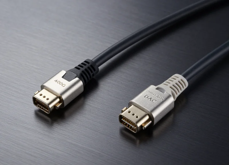
As data centers transition to the 800G era to support AI and high-performance computing, the choice between 2x400G breakout architectures and native connections has become a pivotal strategic decision. This article examines how these solutions stack up against traditional alternatives in the real-world metrics that matter most to network architects.
The Evolution of 800G: Understanding 2x400G Breakout Architecture
The Shift to High-Radix 800G Architectures
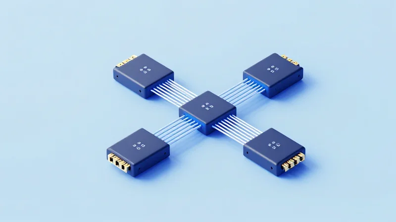
The transition to 800G is not merely a bandwidth upgrade but a structural shift in data center design, where 2x400G breakout solutions provide the necessary granularity to maximize port density while maintaining compatibility with 400G infrastructure. By utilizing a single 800G port to serve two 400G endpoints, operators can double their switch radix without the immediate need for a full-scale optical overhaul.
Hardware Foundation: OSFP vs. QSFP-DD800
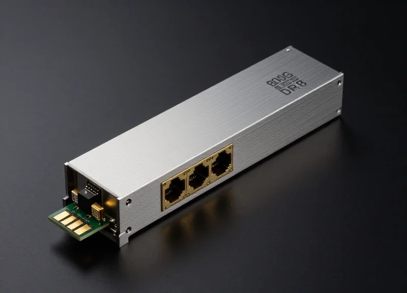
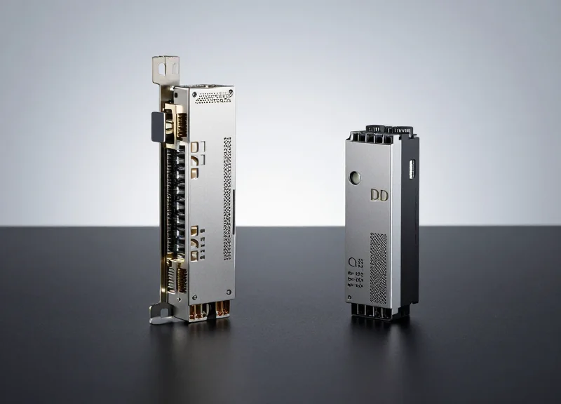
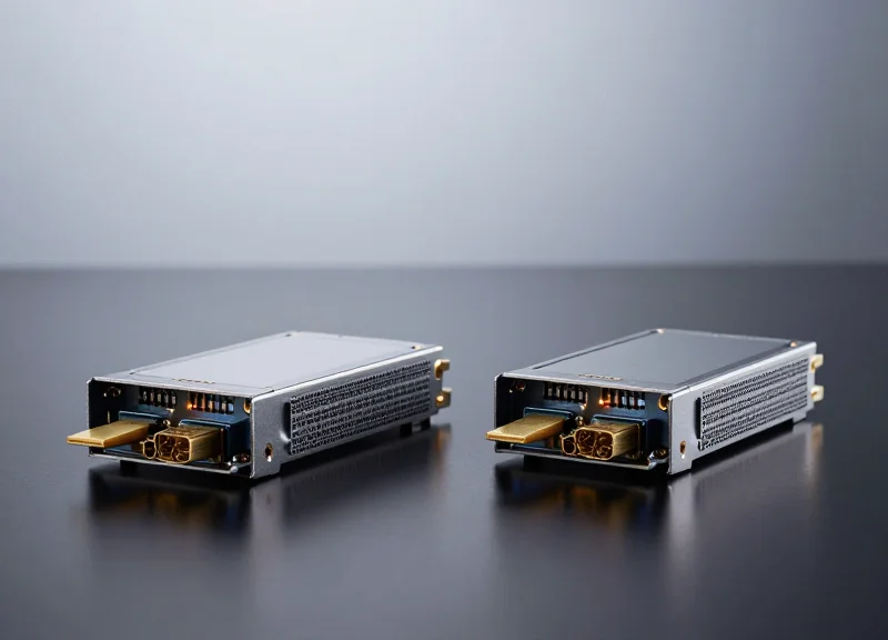
The physical implementation of 2x400G relies on two primary form factors: OSFP (Octal Small Form-factor Pluggable) and QSFP-DD800. Both modules utilize 8 lanes of 112G SerDes to achieve 800G aggregate throughput, yet they differ significantly in thermal management and backward compatibility paths.
| Feature | OSFP (800G) | QSFP-DD800 |
|---|---|---|
| Thermal Efficiency | Superior due to integrated heat sink | Moderate, relies on host-side cooling |
| Backward Compatibility | Requires adapters for QSFP | Directly compatible with legacy QSFP |
| Connector Interface | LC or MPO-16 | MPO-12 or MPO-16 |
| Power Limit | Up to 15W-18W | Up to 14W-16W |
Lane Mapping and Electrical Signaling
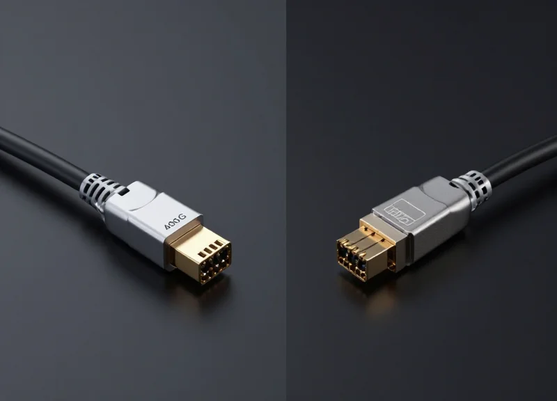
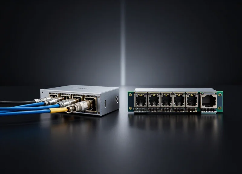
In a 2x400G configuration, the 8x112G PAM4 electrical lanes of the 800G module are bifurcated at the MAC level. This allows the switch to treat a single physical cage as two logical 400G ports. On the optical side, this is typically achieved via dual MPO-12 connectors or specialized MPO-16 cabling, ensuring that each 400G stream has dedicated fiber pairs for independent transmission.
- Why is 2x400G preferred over native 800G in current deployments?
Many existing leaf-spine fabrics are still based on 400G; the breakout allows for high-density 800G spines to connect directly to these 400G leaves without extra hardware. - What is the impact on power consumption?
A single 800G transceiver configured as 2x400G typically consumes less power than two individual 400G transceivers, reducing the overall Watts-per-Gigabit metric. - Does 2x400G support different optical reaches?
Yes, 2x400G breakouts are available in DR8 (500m) and FR8 (2km) variants, mapped as 2xDR4 and 2xFR4 respectively.
Direct Comparison: 2x400G vs. Native 800G and 4x200G Alternatives
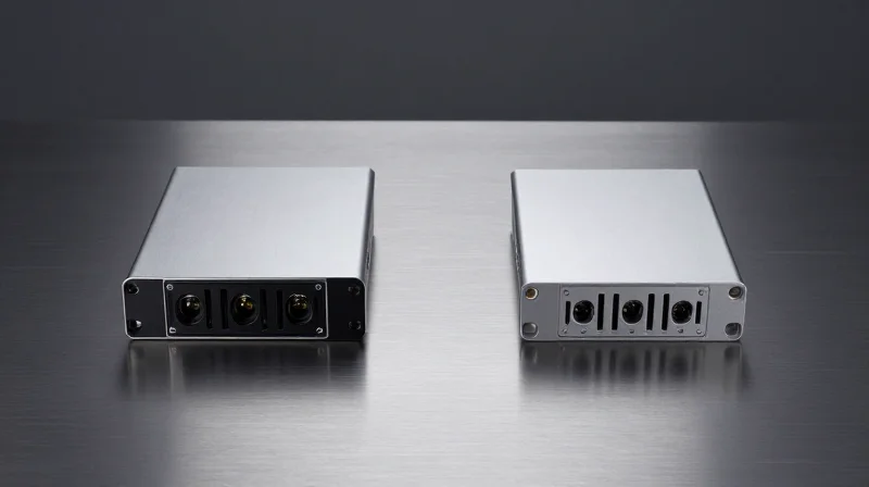
Selecting between 2x400G breakout solutions, native 800G links, and 4x200G alternatives is a multi-dimensional optimization problem involving switch radix, power envelope, and existing infrastructure compatibility. While native 800G provides the cleanest architectural path for future-proofing, 2x400G breakouts currently offer the most versatile transition for hyperscale environments looking to maximize the ROI of 400G-capable leaf switches while upgrading spine capacity to 800G.
Architectural Trade-offs: Throughput vs. Flexibility
The primary differentiator in these configurations lies in how the 800Gbps electrical lane capacity is subdivided. Native 800G uses a single logical channel, minimizing protocol overhead and simplification of cable management. In contrast, 2x400G and 4x200G breakouts leverage the parallel nature of OSFP and QSFP-DD800 modules to split signals into multiple independent paths, effectively doubling or quadrupling the number of downstream devices a single switch port can support.
| Feature | 2x400G Breakout | Native 800G | 4x200G Breakout | ||||
|---|---|---|---|---|---|---|---|
| Primary Use Case | Leaf-to-Spine Interconnect | Backbone/Core Link | High-Density Server Access | Switch Radix Support | High (2x Ports) | Standard (1x Port) | Ultra-High (4x Ports) |
| Cabling Complexity | Moderate (DAC/AOC) | Low (Standard LC/MPO) | High (Complex Breakout) | Power Per Gbps | Optimized | Lowest | Slightly Higher |
| Relative Cost (TCO) | Medium-Low | Medium-High | High |
Native 800G: The Performance Leader
Native 800G is designed for maximum throughput between core layers. By utilizing the full bandwidth of the module without splitting, it reduces the complexity of Forward Error Correction (FEC) synchronization across multiple lanes. This leads to slightly lower latency compared to breakout configurations, which is critical for high-frequency trading and specific AI training workloads where every nanosecond counts.
4x200G: Maximizing Radix in AI Clusters
In massive scale-out AI clusters, increasing the 'radix' (the number of ports per switch) is often more valuable than raw per-port bandwidth. The 4x200G configuration allows a 32-port 800G switch to connect to 128 individual 200G nodes. While this maximizes the number of endpoints, it significantly increases cabling density and requires specialized transceivers that can handle the increased complexity of signal integrity across four separate breakout paths.
Frequently Asked Questions
- Why choose 2x400G over 4x200G?
2x400G offers a better balance between port density and signal integrity. It is less demanding on the switch's SerDes and utilizes standard 400G-DR4 optics, making it more cost-effective than the specialized optics often required for 200G breakout modes. - Does native 800G save on power compared to breakouts?
Yes, native 800G typically consumes less power per gigabit because it avoids the additional DSP processing power required to manage multiple breakout clocking and lane alignment scenarios. - What is the impact on rack space?
Breakout solutions (2x400G and 4x200G) significantly reduce rack space by allowing more servers to connect to a single Top-of-Rack (ToR) switch, reducing the total number of switches required in the fabric.
Latency Benchmarks: The Impact on High-Frequency Trading and AI

In the realm of High-Frequency Trading (HFT) and massive AI clusters, latency is measured in nanoseconds rather than milliseconds, making the choice of 2x400G breakout architecture critical. A 2x400G breakout solution introduces specific performance characteristics related to signal processing and serialization. While physical transmission speed is consistent across fiber, the overhead of Digital Signal Processing (DSP) and the serialization-deserialization (SerDes) cycles required to split an 800G signal into dual 400G streams can introduce micro-deltas in packet arrival times. These deltas, while negligible in standard enterprise IT, can significantly impact the synchronization efficiency of GPU clusters and the competitive execution speeds of HFT algorithms.
Hardware Latency Factors: DSP and Gearbox Overhead
The primary source of latency in 2x400G transceivers is the DSP. In a breakout scenario, the transceiver must manage two distinct 400G logical channels within a single physical form factor. Depending on whether the architecture uses a gearbox to convert 100G electrical lanes to optical signals, the processing delay can vary. For ultra-low latency applications, 'DSP-lite' or Linear Drive (LPO) modules are emerging as alternatives to traditional retimed optics to shave off valuable nanoseconds by removing the clock and data recovery (CDR) and DSP stages.
| Solution Type | Typical Processing Latency | Signal Integrity Type | Best Use Case |
|---|---|---|---|
| Native 800G (Direct) | 100ns - 150ns | Retimed (DSP) | AI Backend Fabric |
| 2x400G Breakout (DAC) | < 5ns | Passive | HFT Execution |
| 2x400G Breakout (Optic) | 150ns - 250ns | Retimed (DSP) | Leaf-Spine Scaling |
| 2x400G LPO (Linear) | < 20ns | Non-Retimed | Low-Latency AI Clusters |
Impact on HFT and AI Training Cycles
For HFT, the objective is deterministic latency. Breakout cables—specifically Passive Direct Attach Cables (DACs)—are favored because they bypass active optical components that introduce variable delays and jitter. In AI training (specifically LLMs), the focus shifts to 'All-Reduce' synchronization times. While a single 2x400G breakout adds minimal latency, the cumulative effect across a multi-tier leaf-spine architecture can influence the 'tail latency.' If one packet is delayed due to transceiver processing or FEC (Forward Error Correction) overhead, the entire GPU compute cycle may stall, waiting for the synchronization packet to arrive.
- Does 2x400G breakout increase hop count?
No, it functions as a physical-layer split, maintaining the same logical hop count while increasing port density at the switch level. - How does FEC affect breakout performance?
Forward Error Correction (FEC) is mandatory for 400G/800G signals and adds the most significant chunk of latency (approx. 100ns+), regardless of whether it is a breakout or direct link. - Is DAC always better for latency?
Yes, for distances under 3 meters, passive DAC breakouts eliminate the DSP latency entirely, making them the standard for HFT racks.
Power Consumption Metrics: Efficiency at Scale
Power Consumption Metrics: Efficiency at Scale
2x400G breakout solutions achieve a superior power profile by consolidating dual 400G channels into a single 800G-class transceiver, typically reducing total power consumption by 25% to 33% per gigabit compared to utilizing two separate 400G modules. This efficiency gain is fundamentally driven by the transition from 7nm to 5nm DSP (Digital Signal Processor) architectures and the elimination of redundant power-conditioning components required for dual-module setups.
Watt-per-Gigabit Comparison
In hyperscale data centers, the energy efficiency of optics is measured in milliwatts per gigabit (mW/G). A standard 400G QSFP-DD transceiver consumes between 10W and 12W. When two of these are deployed to reach 800G of capacity, the power draw is 20W to 24W. In contrast, an 800G module configured for 2x400G breakout usually operates within a 14W to 17W envelope, providing a significant reduction in operational expenditure (OPEX) at scale.
| Solution Configuration | Total Power Draw (W) | Throughput (Gbps) | Efficiency (mW/Gbps) |
|---|---|---|---|
| 2x Discrete 400G (QSFP112/QSFP-DD) | 20W - 24W | 800 | 25.0 - 30.0 |
| 2x400G Breakout (800G Module) | 14W - 17W | 800 | 17.5 - 21.2 |
| Native 800G (Single Stream) | 13W - 16W | 800 | 16.2 - 20.0 |
Thermal Density and Cooling Optimization
The shift to 2x400G breakouts also addresses the 'thermal wall' encountered in high-density rack designs. By reducing the number of active modules in the switch faceplate by half, operators improve airflow and decrease the cumulative heat load. This allows for higher port densities per rack unit (RU) without triggering aggressive fan speed increases, which can consume as much as 15% of total switch power.
Power Management FAQ
- Why is a single 800G module more efficient than two 400G modules?
The primary reason is the DSP consolidation. A single 800G DSP handles all eight lanes of data more efficiently than two separate 400G DSPs. Furthermore, the 800G modules often utilize newer, smaller process nodes (e.g., 5nm vs. 7nm), which inherently consume less power per transistor switch. - Does the use of breakout cables affect power consumption?
Breakout cables themselves are typically passive (DACs) or have negligible power draw (AOCs/Optics). The power savings are realized within the transceiver module and the switch ASIC port logic, not the physical cabling medium. - What is the impact of 2x400G on Total Cost of Ownership (TCO)?
Lower power consumption directly translates to lower cooling costs and reduced electricity bills. Over a three-to-five-year lifecycle, the 30% reduction in power per port can result in thousands of dollars in savings per rack.
Total Cost of Ownership (TCO) Breakdown

The Total Cost of Ownership (TCO) for 2x400G breakout solutions is defined by a strategic trade-off: higher initial transceiver costs are systematically offset by drastic reductions in port-per-gigabit pricing, reduced power consumption, and a smaller physical footprint that minimizes rack rental and cooling expenses over a 3-5 year lifecycle.
Capex Analysis: Transceivers and Infrastructure
In the immediate term, capital expenditure is dominated by the cost of high-density optics. A 2x400G OSFP or QSFP-DD transceiver typically commands a higher price tag than a standard 400G module; however, because one 2x400G module serves the capacity of two discrete units, the cost per bit is often 15% to 20% lower. This efficiency extends to the switch hardware, where using breakout configurations allows operators to maximize the bandwidth of 800G-capable ASICs without purchasing double the amount of physical switch hardware.
| Component | 2x400G Breakout | Native 800G (DR8) | 2x Discrete 400G |
|---|---|---|---|
| Transceiver Unit Cost | High (Single Unit) | Very High | Moderate (x2 Units) |
| Cabling Infrastructure | MPO-16/Breakout | MPO-16 Direct | Dual MPO-12/Duplex |
| Switch Port Utilization | 1 Port (800G) | 1 Port (800G) | 2 Ports (400G) |
| Cost per Gbps | Lowest | Premium | Moderate |
Opex and Long-Term Lifecycle Metrics
Operational expenditure is where 2x400G solutions provide the most significant competitive advantage. By consolidating high-speed lanes, data centers reduce the number of active components that require power and cooling. Over a five-year window, the cumulative energy savings from using 800G ports in a 2x400G breakout mode—compared to a legacy 400G infrastructure—can account for nearly 12% of the total hardware investment cost.
| Opex Category (5-Year) | 2x400G Impact | Estimated Savings (%) |
|---|---|---|
| Power Consumption | ASIC Consolidation Efficiency | 10 - 15% |
| Cooling Overhead | Lower thermal density per Gbps | 8 - 12% |
| Maintenance & Logistics | Fewer Field Replaceable Units (FRUs) | 20 - 25% |
| Rack Space (Real Estate) | Doubled density per RU | 50% |
FAQ: Financial Impact and ROI
- Is the ROI faster for 2x400G compared to native 800G?
Yes. Because 400G ecosystems are more mature, the cost of 400G-compatible downstream hardware is lower, leading to an ROI break-even point typically 6-9 months sooner than native 800G deployments. - How do breakout cables affect the maintenance budget?
Breakout cables introduce slightly more complexity in cable management, but they reduce the number of total cables required by 50%, simplifying the inventory of spares and reducing long-term management labor. - What is the primary risk to TCO in these configurations?
The 'blast radius' is the primary risk. A single failure in a 2x400G transceiver impacts two 400G links simultaneously. This requires a robust redundancy strategy to ensure maintenance costs don't spike during component failures.
Physical Infrastructure and Rack Space Optimization
Physical Infrastructure and Rack Space Optimization
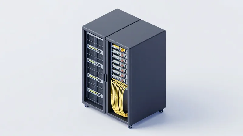
2x400G breakout solutions serve as the critical bridge between high-radix 800G switch architectures and 400G end-nodes, effectively doubling the usable bandwidth per rack unit (RU) without increasing the physical volume of cabling. By consolidating two 400G channels into a single 800G port via OSFP or QSFP-DD800 form factors, data center operators can reclaim up to 50% of their patch panel and cable tray space, which is essential for maintaining airflow in high-density AI and HPC clusters.
Mitigating the 'Cable Jungle' in High-Density Pods
In a traditional 400G deployment, every port requires an individual cable run. As clusters scale to thousands of GPUs or CPUs, the resulting 'cable jungle' creates significant thermal bottlenecks. 2x400G solutions simplify this by utilizing twin-port transceivers and breakout DACs/AECs. This consolidation minimizes the cross-sectional area of cable bundles in the back-of-rack space, ensuring that cold aisle air reaches the equipment intakes with minimal resistance, thereby reducing the operational cost of cooling.
| Infrastructure Metric | Discrete 400G Links | 2x400G Breakout (from 800G Port) | Physical Impact |
|---|---|---|---|
| Cables per 3.2Tbps | 8 Cables | 4 Cables | 50% Reduction |
| Switch Port Utilization | 8 x 400G Ports | 4 x 800G Ports | High Radix Advantage |
| Airflow Resistance | High | Low-Medium | Improved Thermal Profile |
| Patch Panel Density | 1x Density | 2x Density | Space Reclamation |
Strategic Rack Space Reclamation
The transition to 2x400G optics also impacts the Top-of-Rack (ToR) switch selection. By using 800G-capable switches in a breakout configuration, data centers can support more nodes per rack with fewer switches. This reduces the 'U' count required for networking gear, leaving more space for revenue-generating compute or storage hardware. Furthermore, structured cabling using MPO-16 or dual-LC connectors in 2x400G transceivers simplifies the migration path from legacy 400G to future native 800G/1.6T environments.
- How does 2x400G affect cable management complexity?
It significantly reduces complexity by halving the number of physical cables required to achieve the same aggregate bandwidth, leading to cleaner cable runs and easier maintenance. - What is the impact on cooling and power efficiency?
Lower cable density improves airflow across the rack, reducing the strain on fan units and lowering the overall cooling PUE (Power Usage Effectiveness) for the data center. - Does 2x400G require specialized rack hardware?
While it uses standard rack units, it often requires high-density patch panels and careful consideration of bend radius for breakout cables (DACs/AECs) to ensure long-term signal integrity.
Interoperability and Ecosystem Readiness
Ecosystem readiness for 2x400G breakout solutions is currently at an inflection point, characterized by broad hardware support across Tier-1 switch vendors and stabilized industry standards like the QSFP-DD800 and OSFP MSAs. Unlike earlier iterations of breakout technology which suffered from proprietary constraints, today's 2x400G solutions leverage standardized 112G SerDes lanes, making them natively compatible with the latest generation of 51.2T switches and high-performance NICs. This interoperability allows network architects to deploy high-density 800G ports while maintaining a seamless, low-latency path to existing 400G infrastructure without requiring complex protocol conversion.
Industry Standards and MSA Compliance
The foundation of 2x400G interoperability lies in adherence to the IEEE 802.3ck standard for 100Gb/s electrical signaling and the Multi-Source Agreements (MSA) that define the physical and management interfaces. QSFP-DD (Double Density) and OSFP (Octal Small Form-factor Pluggable) modules utilize Common Management Interface Specification (CMIS) version 4.0 and higher, which facilitates standardized diagnostic monitoring and control across different vendor platforms. This standardization ensures that a 2x400G transceiver from Vendor A can be managed by a switch from Vendor B, provided the Network Operating System (NOS) has been updated to recognize the 8x100G port configuration.
Hardware Support and Silicon Compatibility
The shift toward 2x400G is largely driven by the availability of high-radix switch silicon. The following table highlights the current state of support across major silicon families used in hyperscale and enterprise environments.
| Silicon Family | Throughput | 2x400G Native Support | Primary Form Factors |
|---|---|---|---|
| Broadcom Tomahawk 5 | 51.2 Tbps | Full Support (Native 112G) | OSFP, QSFP-DD800 |
| NVIDIA Spectrum-4 | 51.2 Tbps | Full Support | OSFP |
| Cisco Silicon One G100 | 25.6 / 51.2 Tbps | Full Support | QSFP-DD800 |
| Broadcom Tomahawk 4 | 25.6 Tbps | Partial (Requires 50G SerDes) | QSFP-DD |
Vendor Interoperability Challenges and Best Practices
While the physical layer is standardized, multi-vendor interoperability still requires attention to FEC (Forward Error Correction) settings. For a 2x400G breakout (8x100G) to communicate effectively with two 400G-DR4 units, both ends must support KP4 FEC. Furthermore, while OSFP modules offer superior thermal performance for 800G applications, the choice between OSFP and QSFP-DD often depends on existing legacy port investments. It is recommended to verify the EEPROM coding of the breakout cables, as many switches require specific vendor-specific signatures to enable the port without generating 'unsupported transceiver' errors.
Frequently Asked Questions
- Can I use 2x400G breakout cables with older 12.8T switches?
Generally no, as 12.8T switches typically utilize 50G SerDes, whereas 2x400G solutions are optimized for 112G SerDes. Attempting this would require active gearboxes, significantly increasing cost and power. - Is software configuration different for 2x400G ports?
Yes, the NOS must be configured to 'split' the 800G physical port into two logical 400G interfaces. This command varies by vendor (e.g., 'interface breakout' in Cisco NX-OS or 'port split' in SONiC). - Does the 2x400G solution support different reaches on each breakout leg?
No, because both 400G legs share the same internal laser source and optical assembly within the 800G module, they must typically adhere to the same distance specification (e.g., 500m for DR4 or 2km for FR4).
Future-Proofing Your Network: Scaling to 1.6T and Beyond
Future-Proofing Your Network: Scaling to 1.6T and Beyond
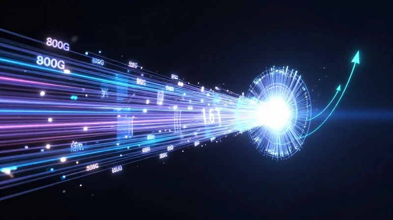
Future-proofing a high-performance network requires an architectural bridge where 2x400G breakout solutions provide the immediate port density needed for 800G ecosystems while establishing the cabling, thermal, and power foundations required for the shift to 224G-per-lane signaling. By adopting 2x400G designs today, network architects are essentially pre-configuring their radix and fiber plant to support the eventual 1.6Tbps throughput leap without requiring a complete hardware overhaul.
The 224G SerDes Evolution and 1.6T Optics
The primary driver behind 1.6T networking is the transition from 112G SerDes to 224G SerDes. While current 800G optics utilize eight lanes of 100G, 1.6T modules will utilize eight lanes of 200G. This doubling of lane speed demands significantly higher signal integrity and places a premium on Very Small Form Factor (VSFF) connectors like SN and MDC. These connectors, already popular in 2x400G breakout scenarios, are becoming the standard for the 1.6T era because they allow for cleaner, more manageable breakout paths at the transceiver faceplate.
| Network Standard | Lane Speed (SerDes) | Aggregate Bandwidth | Common Connectors | Primary Use Case |
|---|---|---|---|---|
| 400G | 56G / 112G | 400 Gbps | QSFP-DD / MPO-12 | Standard Cloud Aggregation |
| 800G (2x400G) | 112G | 800 Gbps | OSFP / SN / MDC | AI/ML Clusters & High Density |
| 1.6T | 224G | 1,600 Gbps | OSFP1600 / OSFP-XD | Next-Gen AI & Terabit Core |
Strategic Infrastructure Considerations
- How do 2x400G breakouts simplify the 1.6T migration?
They establish a multi-lane logical architecture that mirrors future 1.6T-to-2x800G or 1.6T-to-4x400G breakout patterns, allowing operators to reuse existing fiber management and patching workflows. - Is existing fiber cabling compatible with 1.6T?
Standard Single Mode Fiber (SMF) remains compatible, but the shift to 1.6T requires higher-density VSFF cabling to manage the increased number of logical channels without overwhelming rack space. - What are the thermal implications of scaling beyond 800G?
1.6T modules are expected to reach power envelopes of 25W to 30W. Future-proofing requires implementing cooling-optimized form factors, such as the OSFP design, which features integrated fins for superior heat dissipation. - Will 2x400G solutions become obsolete?
No; they will likely remain the standard for edge-to-spine connectivity as the core shifts to 1.6T, acting as a lower-cost, high-reliability tier in a multi-speed fabric.
Ultimately, the choice between 2x400G and its alternatives should be viewed through the lens of long-term lifecycle management. Networks that invest in OSFP-based 800G infrastructure today are better positioned to adopt 1.6T modules tomorrow, as they already account for the thermal and connector densities that will be mandatory for the next decade of data center growth.
Choosing between 2x400G breakout solutions and alternatives requires a careful balance of immediate performance needs and long-term cost goals. For a personalized TCO assessment and expert guidance on your next-generation network deployment, contact our engineering team today.