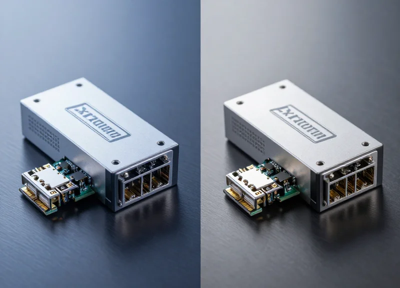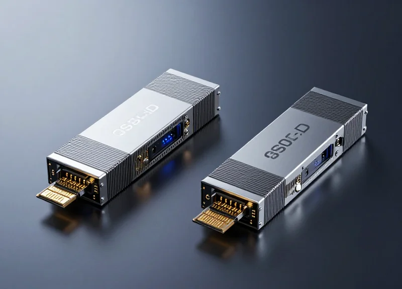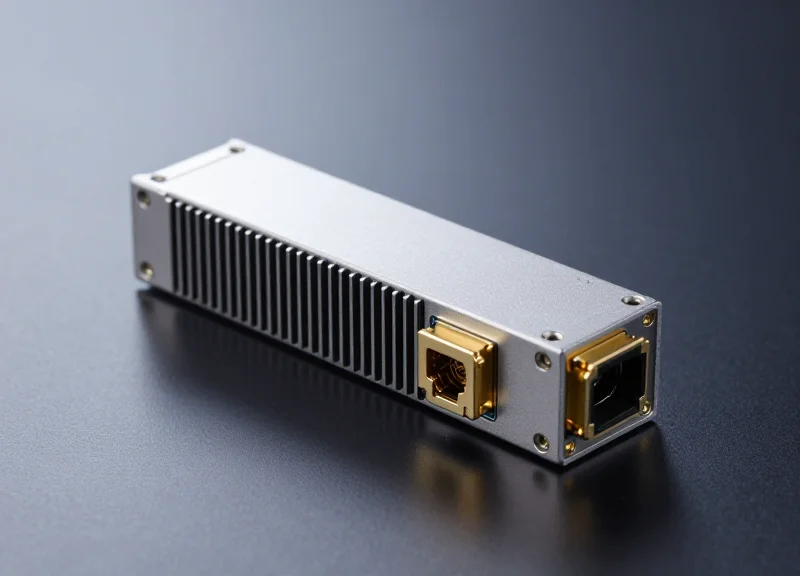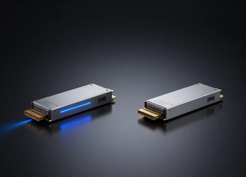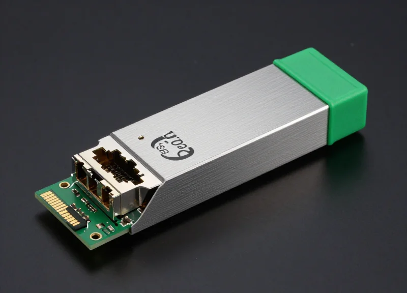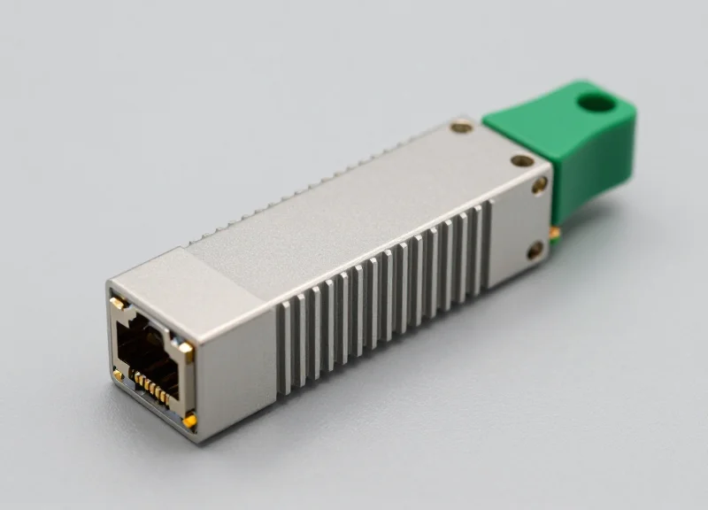
As data centers transition to 100G and beyond, the QSFP28 SR4 module remains the workhorse for short-reach connectivity. This guide breaks down the complex engineering behind these modules and why they are essential for modern network infrastructure.
The Evolution of 100G Form Factors
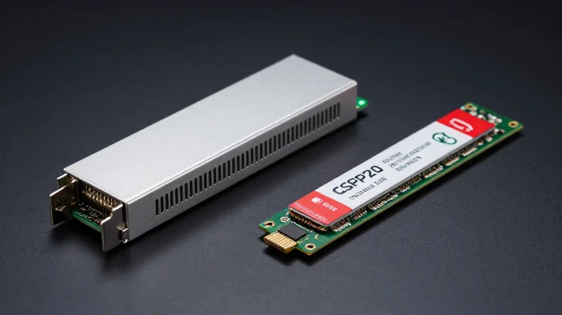
The evolution of 100G form factors represents a decade-long engineering feat focused on miniaturization and thermal efficiency. Initially launched to support long-haul telecommunications, early 100G modules like the CFP (C Form-factor Pluggable) were nearly the size of a smartphone, consuming significant power and limiting port density. As the industry pivoted toward hyperscale data centers, the need for a smaller, more efficient interface led to the development of CFP2, CFP4, and eventually the Quad Small Form-factor Pluggable 28 (QSFP28), which remains the industry standard for 100G density today.
The CFP Family: The Pioneers of 100G
The CFP was the first multi-source agreement (MSA) to support 100GbE. While revolutionary, its physical dimensions restricted switch manufacturers to only a few ports per rack unit. Subsequent iterations—CFP2 and CFP4—reduced the footprint by approximately 50% each time. Despite these improvements, the CFP family still struggled to meet the power-per-gigabit requirements of high-performance leaf-and-spine architectures.
QSFP28: The Game Changer for Density
The arrival of QSFP28 marked a critical turning point. Unlike its predecessors, QSFP28 shares the same physical dimensions as the 40G QSFP+ module but supports four lanes of 25Gbps each. This allows network operators to upgrade from 40G to 100G without redesigning rack layouts or replacing existing cable management, providing a seamless path to higher bandwidth with significantly reduced power draw.
| Form Factor | Relative Size | Typical Power | Max Port Density (1RU) |
|---|---|---|---|
| CFP | 100% | 24W | 4-8 Ports |
| CFP2 | 50% | 12W | 8-16 Ports |
| CFP4 | 25% | 6W | 16-24 Ports |
| QSFP28 | 10% | <3.5W | 32-48 Ports |
Common Questions on 100G Evolution
- Why is it called QSFP28?
The 'Q' stands for Quad (4 lanes), and '28' refers to the fact that each electrical lane can handle up to 28Gbps to accommodate both 100GbE and OTU4 transmission rates. - Are different 100G form factors compatible?
They are not physically compatible due to different sizes and pin configurations. However, they can interoperate over a fiber link if they share the same optical specifications, such as 100G-LR4 or 100G-SR4. - What drove the shift from CFP to QSFP28?
The primary drivers were port density and power efficiency. QSFP28 allows for 3.2Tbps or higher in a single rack unit, which was impossible with the larger CFP modules.
Deconstructing the 'SR4' Nomenclature

The 'SR4' designation is a specific industry descriptor defined by the IEEE 802.3 standards to categorize the physical layer of the transceiver. 'SR' stands for Short Range, which dictates the use of 850nm Vertical-Cavity Surface-Emitting Laser (VCSEL) technology over multimode fiber, while the '4' indicates a parallel architecture consisting of four independent transmit and receive channels, each operating at 25.78 Gbps to achieve a total aggregate bandwidth of 100 Gbps.
Decoding 'SR': Wavelength and Media Type
The 'SR' prefix primarily identifies the reach and the optical media required for the link. These modules are engineered for data center environments where cable runs are relatively short. Because they utilize 850nm lasers, they are compatible with Multi-Mode Fiber (MMF) which is less expensive than Single-Mode Fiber (SMF) for high-density, short-distance deployments.
| Designation | Attribute | Specification |
|---|---|---|
| SR | Range Type | Short Range (typically up to 100m) |
| 850nm | Wavelength | VCSEL-based infrared light |
| MMF | Fiber Type | OM3, OM4, or OM5 Multi-Mode Fiber |
Understanding the '4': Parallel Optical Interface
Unlike serial transmission which sends data over a single fiber pair, the '4' in SR4 represents a parallel design. This requires an MPO (Multi-fiber Push-On) connector, typically an MPO-12 or MPO-8. Inside the cable, four separate strands of fiber are used to transmit data (Tx) and another four are used to receive data (Rx). This 4-lane approach was essential for transitioning from 10G and 40G to 100G without requiring significantly higher-frequency laser components that were not yet commercially viable for short-reach modules at the time of the standard's inception.
Technical Breakdown of 'SR4' Components
- Why 4 lanes instead of 1?
Utilizing four 25G lanes reduces the technical complexity and heat generation compared to a single 100G serial laser, making the QSFP28 form factor thermally efficient. - What is the significance of the 850nm wavelength?
850nm is the standard wavelength for multimode fiber, allowing for the use of low-cost VCSELs which are significantly cheaper to manufacture than the DFB lasers used in long-range modules. - Does SR4 support breakout configurations?
Yes, the 4-lane parallel structure is exactly what allows a 100G SR4 port to be broken out into four individual 25G SFP28 SR connections using a breakout cable.
By deconstructing the nomenclature, it becomes clear that SR4 is optimized for a specific niche: maximum density and lowest cost over distances under 100 meters. For network architects, choosing SR4 means committing to a parallel cabling infrastructure (MPO) rather than the duplex LC cabling used in 'LR' (Long Range) or 'DR' (Datacenter Range) standards.
Core Technical Specifications
Core Technical Specifications of 100G QSFP28 SR4
The 100G QSFP28 SR4 transceiver is engineered to support 100 Gigabit Ethernet links over multimode fiber, utilizing an aggregate data rate of 103.1 Gbps composed of four independent 25.78 Gbps lanes. It represents the industry standard for short-range data center interconnects due to its balance of high-density integration and cost-effective VCSEL technology.
| Parameter | Specification |
|---|---|
| Data Rate | 103.1 Gbps (4 x 25.78 Gbps) |
| Wavelength | 850 nm |
| Fiber Type | Multimode Fiber (OM3/OM4/OM5) |
| Max Reach | 70m (OM3) / 100m (OM4) / 150m (OM5) |
| Connector Type | MPO-12 (Male) |
| Power Consumption | Typically < 2.5W (Max 3.5W) |
| Transmitter Type | VCSEL |
| Receiver Type | PIN |
| Digital Diagnostic Monitoring (DDM) | Supported |
Optical Transmission and Signal Integrity
The SR4 module operates at a nominal wavelength of 850nm, leveraging Vertical-Cavity Surface-Emitting Laser (VCSEL) technology. This design is optimized for short-distance transmission over parallel multimode fiber. By using four discrete lanes for both transmission and reception, the module avoids the complexity of wavelength division multiplexing (WDM), which simplifies the internal architecture and reduces latency. Signal integrity is maintained through Clock and Data Recovery (CDR) circuits on both the transmit and receive paths, ensuring robust performance across high-speed switch fabrics.
Power Efficiency and Thermal Performance
Efficiency is a hallmark of the QSFP28 form factor. The SR4 variant typically operates at a power consumption level well below 2.5W, though it is rated for up to 3.5W (Power Class 4). This low thermal footprint allows for higher port density on top-of-rack switches without exceeding cooling capacities. The standard operating temperature for commercial-grade modules ranges from 0°C to 70°C, monitored in real-time via the integrated DDM interface which tracks temperature, voltage, and bias current.
- Does 100G SR4 support FEC?
Yes, 100G QSFP28 SR4 requires Host Forward Error Correction (FEC), specifically RS-FEC (IEEE 802.3bj Clause 91), to achieve a Bit Error Rate (BER) better than 1E-12. - What is the significance of the 850nm wavelength?
850nm is the standard wavelength for multimode fiber applications, allowing for the use of low-cost VCSEL transmitters which are ideal for short-reach data center spans. - Is the power consumption fixed at 3.5W?
No, 3.5W is the maximum power class limit defined by the MSA; most modern 100G SR4 modules operate efficiently between 1.8W and 2.5W depending on the manufacturer.
Cabling and Connectivity: The Role of MPO/MTP
Cabling and Connectivity: The Role of MPO/MTP
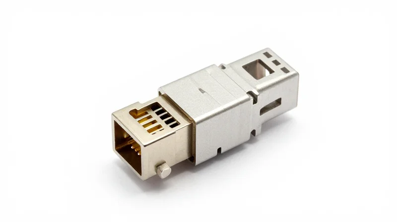
The 100G QSFP28 SR4 module relies on parallel optics technology, necessitating Multi-fiber Push-On (MPO) or Multi-fiber Termination Push-on (MTP) connectors to facilitate high-speed data transmission over Multi-Mode Fiber (MMF). Unlike traditional duplex fiber connections that use one fiber for transmission and one for reception, the SR4 architecture uses multiple parallel lanes, making the MPO/MTP interface the standard physical layer requirement for achieving 100Gbps throughput in short-reach applications.
The 12-Fiber MPO/MTP Interface
While the QSFP28 SR4 module utilizes a 12-fiber MPO/MTP connector, it effectively only uses 8 of the 12 available fiber strands. The four outermost fibers on one side are dedicated to transmitting (TX) 25Gbps signals each, while the four outermost fibers on the opposite side are used for receiving (RX). The central four fibers remain dark or unused. This 'Base-8' configuration is critical for network engineers to understand when planning patch panels and trunk cabling to avoid unnecessary fiber waste and ensure proper lane alignment.
Fiber Media Types and Distance Limitations
The reach of a 100G QSFP28 SR4 link is strictly determined by the grade of Multi-Mode Fiber used. Because the 850nm VCSEL lasers are subject to modal dispersion, higher-quality glass with greater modal bandwidth is required to sustain signal integrity over longer distances.
| Fiber Type | Core Diameter | Modal Bandwidth (850nm) | Max Distance (100G SR4) |
|---|---|---|---|
| OM3 | 50/125µm | 2000 MHz*km | 70 Meters |
| OM4 | 50/125µm | 4700 MHz*km | 100 Meters |
| OM5 | 50/125µm | 4700 MHz*km (WBMMF) | 100 Meters |
OM4 remains the most common choice for data center deployments due to its balance of cost and performance, providing the full 100-meter reach specified by the IEEE 802.3bm standard. OM5, or Wideband Multi-Mode Fiber (WBMMF), is fully backward compatible with SR4 but is specifically optimized for Shortwave Wavelength Division Multiplexing (SWDM) applications, which are distinct from the parallel architecture of the SR4.
Connectivity Best Practices
- Why is polarity important for SR4 links?
Because SR4 uses parallel fibers, maintaining correct 'Polarity' (Type A, B, or C) ensures that the transmitter on one end connects to the receiver on the other. Type B (crossover) is most frequently used in 100G MPO-to-MPO connections. - Can I use MPO-12 or MPO-8 cables?
Yes, both can work. A 12-fiber MPO cable will simply have 4 idle fibers, while an 8-fiber MPO cable is purpose-built for the SR4's parallel lanes, potentially simplifying cable management in high-density racks. - Does cleanliness affect SR4 performance?
Significantly. MPO connectors have a large surface area; a single speck of dust on one of the 12 fiber ends can cause a total link failure or high Bit Error Rates (BER) across the entire 100G channel.
Digital Diagnostic Monitoring (DDM) Functions

Digital Diagnostic Monitoring (DDM) Functions
Digital Diagnostic Monitoring (DDM), also referred to as Digital Optical Monitoring (DOM), is a critical feature of the 100G QSFP28 SR4 transceiver that allows network administrators to monitor the real-time health of the optical link. By utilizing an I2C interface, the module provides a window into its internal operational status, reporting data on power consumption, temperature, and signal integrity without interrupting high-speed traffic flow.
Critical Telemetry Parameters
Modern 100G QSFP28 SR4 modules adhere to the SFF-8636 management interface standard, which defines the reporting of five key metrics. These parameters enable precise performance tracking and predictive failure analysis.
| Parameter | Description | Significance |
|---|---|---|
| Transceiver Temperature | Internal operating temperature in degrees Celsius. | Prevents thermal damage and identifies cooling failures. |
| Supply Voltage | The internal voltage provided to the transceiver circuitry. | Detects power supply instability before it causes errors. |
| Laser Bias Current | The electrical current applied to the VCSEL laser diodes. | Indicates laser aging; a spike often precedes component failure. |
| TX Optical Power | The average output power of the transmitted signal (dBm). | Verifies that the transmitter is operating within spec limits. |
| RX Optical Power | The average power of the signal received from the fiber (dBm). | Essential for identifying cable issues or excessive attenuation. |
Proactive Maintenance and Threshold Alarms
The true value of DDM lies in its alarm and warning threshold system. Each QSFP28 SR4 module has factory-preset upper and lower limits for the parameters mentioned above. When a metric, such as RX power, falls below a specific threshold, the transceiver triggers an interrupt or flag in its internal memory. This allows the host switch or router to generate an alert, enabling IT teams to replace a degrading cable or transceiver during a scheduled maintenance window rather than responding to an emergency midnight outage.
- How does DDM assist in troubleshooting fiber link issues?
DDM allows technicians to distinguish between transceiver failure and fiber path issues. For example, if TX power is normal but RX power is low, the fault likely lies in the MPO cable or a dirty connector rather than the module itself. - Does using DDM impact the 100G data transmission speed?
No, DDM operates on a separate low-speed management channel (I2C) and does not consume any bandwidth from the 100Gbps high-speed data path. - Is DDM standard on all 100G QSFP28 SR4 modules?
While virtually all modern enterprise-grade QSFP28 SR4 modules include DDM, it is important to verify compliance with the SFF-8636 MSA to ensure full visibility in multi-vendor environments.
Comparative Analysis: SR4 vs. LR4 vs. PSM4
Comparative Analysis: SR4 vs. LR4 vs. PSM4
Choosing the correct 100G QSFP28 module is a strategic decision that hinges on the existing fiber plant, the required link distance, and the available budget for both transceivers and cabling. While the 100G SR4 is the undisputed leader for short-range data center interconnects using multimode fiber, the LR4 and PSM4 standards serve critical roles in extending 100G throughput across longer distances using single-mode fiber (SMF).
Side-by-Side Specification Comparison
| Feature | 100G QSFP28 SR4 | 100G QSFP28 LR4 | 100G QSFP28 PSM4 |
|---|---|---|---|
| Fiber Type | Multimode (OM3/OM4) | Single-Mode (G.652) | Single-Mode (G.652) |
| Wavelength | 850nm | 1295nm - 1309nm (LAN-WDM) | 1310nm |
| Max Distance | 100m (OM4) | 10km | 500m |
| Connector | MPO-12 (12-fiber) | Duplex LC (2-fiber) | MPO-12 (12-fiber) |
| Modulation | NRZ | NRZ | NRZ |
| Transceiver Cost | Lowest | Highest | Medium |
Decision Factors: Distance and Cabling Economics
The primary differentiator between these three standards is the trade-off between transceiver cost and cabling cost. The 100G SR4 uses inexpensive VCSEL lasers but requires 8 or 12 fibers per link, making it ideal for high-density, short-reach applications (under 100m) where multimode fiber is already prevalent. In contrast, the 100G LR4 utilizes an internal WDM multiplexer to combine four channels into a single duplex LC fiber pair. While the LR4 transceiver is more expensive due to the complex laser and MUX/DEMUX components, it significantly reduces the cost of long-haul cabling (up to 10km) by requiring only two fibers per link. The 100G PSM4 occupies a middle ground; it uses single-mode fiber with a parallel MPO architecture (like SR4) to reach up to 500m, providing a cost-effective alternative for medium distances when compared to the LR4, provided the user is willing to manage higher fiber counts.
Quick Selection Guide
- When should I use SR4 over PSM4?
Use SR4 for indoor data center applications within a single rack or between adjacent racks where the distance is less than 100m and OM3/OM4 multimode fiber is used. - Is PSM4 compatible with SR4 cabling?
While both use MPO-12 connectors, they are NOT compatible because SR4 uses multimode fiber and PSM4 uses single-mode fiber. Connecting them will result in signal loss and potential hardware damage. - Why choose LR4 for 2km links if PSM4 is cheaper?
LR4 is chosen for links exceeding 500m up to 10km. Additionally, if your facility is pre-wired with duplex LC single-mode fiber, LR4 is the only option that avoids the need to pull new 12-fiber MPO cables. - Which module has the lowest power consumption?
The SR4 typically has the lowest power consumption (under 2.5W or 3.5W depending on vendor) because it lacks the complex thermal management and optical multiplexing required by the LR4.
Deployment Use Cases in Leaf-Spine Architectures
Deployment Use Cases in Leaf-Spine Architectures
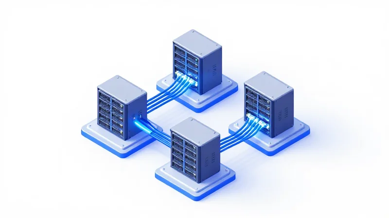
The 100G QSFP28 SR4 transceiver serves as the critical interconnect technology for short-reach, high-bandwidth links within modern leaf-spine data center fabrics, primarily facilitating rapid data movement between Top-of-Rack (ToR) switches and spine layers or high-performance servers. By utilizing parallel multimode fiber (MMF), these modules provide a cost-optimized solution for the majority of intra-data center connections that do not exceed 100 meters.
ToR-to-Server High-Speed Interconnects
As compute-intensive workloads such as AI training and big data analytics become standard, the demand for 100G connectivity at the server level has grown. The QSFP28 SR4 is the preferred module for connecting high-performance servers equipped with 100G NICs to Top-of-Rack switches. Compared to copper solutions like DACs, which are limited to approximately 5 meters at 100G, the SR4 allows for more flexible rack layouts and improved airflow due to the thinner diameter of the MPO/MTP cabling.
Leaf-to-Spine Aggregation
In leaf-spine architectures, the goal is to minimize latency and maximize throughput across the fabric. QSFP28 SR4 modules are deployed on the uplink ports of leaf switches to connect to the spine layer. In most enterprise data centers and colocation facilities, the distance between the leaf and spine falls well within the 70m to 100m range supported by OM3 and OM4 fiber, making SR4 the most economical optical choice compared to single-mode alternatives.
| Fiber Type | Max Distance (100G SR4) | Typical Application |
|---|---|---|
| OM3 MMF | 70 Meters | Intra-rack or adjacent rack patching |
| OM4 MMF | 100 Meters | Standard Leaf-to-Spine interconnects |
| OM5 MMF | 150 Meters | Extended reach within larger data halls |
Breakout Configurations for Density Optimization
One of the most versatile use cases for the QSFP28 SR4 is the 4x25G breakout mode. A single 100G port on a spine or leaf switch can be partitioned into four 25G logical ports using an MPO-to-4xLC breakout cable. This allows network architects to support legacy 25G hardware while maintaining a migration path to full 100G, effectively quadrupling the port density of the existing switch chassis.
Deployment FAQ
- Is the QSFP28 SR4 compatible with existing 40G QSFP+ cabling?
While both use MPO-12 connectors, the SR4 requires 100G-rated transceivers at both ends. However, the existing OM3/OM4 fiber infrastructure used for 40G SR4 can typically be reused for 100G SR4 deployments. - When should I choose SR4 over AOC (Active Optical Cables)?
AOCs are ideal for fixed-length, 'set-and-forget' links within a single rack. SR4 transceivers with separate MPO cables are preferred for structured cabling environments where you need to run fiber through patch panels or across different rows. - How does SR4 impact data center cooling?
Because SR4 transceivers use low-power VCSEL lasers (typically <3.5W), they generate less heat than long-reach single-mode modules, contributing to better overall Power Usage Effectiveness (PUE) in high-density deployments.
Ensuring Interoperability and Third-Party Compatibility
Ensuring Interoperability and Third-Party Compatibility
The successful deployment of 100G QSFP28 SR4 modules in a multi-vendor environment depends on the module's ability to satisfy the host switch's internal software checks while maintaining physical and electrical adherence to industry standards. While the hardware is standardized by the Multi-Source Agreement (MSA), the software layer—specifically the EEPROM coding—is where most compatibility hurdles occur. To ensure high-performance connectivity, network architects must verify that third-party transceivers are coded to emulate original equipment manufacturer (OEM) signatures while providing accurate Digital Diagnostic Monitoring (DDM) data back to the host system.
The Role of EEPROM and MSA Standards
The EEPROM on a QSFP28 SR4 module serves as its 'identity card,' storing critical information such as the vendor name, serial number, and part number. This data is structured according to SFF-8636 and SFF-8665 standards. Many Tier-1 switch vendors implement proprietary 'handshake' protocols that query these specific EEPROM registers. If the returned value does not match the vendor's whitelist, the switch may disable the port or trigger a warning, such as 'Non-supported transceiver detected.'
| Compatibility Factor | MSA Standard Transceiver | Vendor-Locked Transceiver |
|---|---|---|
| EEPROM Layout | Standardized (SFF-8636) | Standardized with Proprietary Keys |
| Port Status | Plug-and-play on open platforms | May be 'Err-Disabled' without coding |
| DDM Access | Available via standard I2C | May be restricted by host software |
| Cost Efficiency | High (Third-party flexibility) | Low (Premium OEM pricing) |
Best Practices for Testing and Validation
Validating 100G QSFP28 SR4 compatibility involves more than just link-up status. A comprehensive testing protocol ensures long-term stability and prevents intermittent packet loss.
- EEPROM Verification
Use a transceiver coder to verify that the vendor ID and checksums match the target switch's requirements, specifically for brands like Cisco, Arista, and Juniper. - I2C Bus Stability Check
Monitor the communication between the switch and the module to ensure that the I2C interface does not suffer from timing issues that could lead to DDM reporting errors. - Bit Error Rate Testing (BERT)
Run traffic at 100G capacity using a network tester to ensure the transceiver maintains a pre-FEC Bit Error Rate of less than 5E-5 as per IEEE 802.3bm requirements. - Physical Tolerance Testing
Conduct hot-swapping tests across different switch models to confirm that the module initializes correctly within the expected boot-up window.
Common Interoperability FAQs
- Can I mix different brands of QSFP28 SR4 on the same link?
Yes. As long as both modules adhere to the IEEE 802.3bm standard and the MPO-12 connectors are properly aligned, the brand of the transceiver at each end does not need to match. - What happens if the switch firmware is updated?
Some firmware updates change the transceiver validation algorithm. It is vital to use third-party modules that support field-reprogramming to update the EEPROM coding if a vendor introduces new software locks. - Is DDM monitoring always available on third-party modules?
Most high-quality third-party SR4 modules provide full DDM support. However, some lower-tier options may lack real-time reporting of laser bias or optical power, which is essential for proactive maintenance.
Future-Proofing Your High-Speed Infrastructure
The Path Beyond 100G: Strategy for Scalable Infrastructure
Future-proofing a high-speed infrastructure built on 100G QSFP28 SR4 requires a strategic focus on physical layer consistency, specifically the continued utilization of MPO-12 cabling and the adoption of OM4 or OM5 wideband multimode fiber (WBMMF). By maintaining a modular approach to optics and prioritizing standards that support breakout configurations, organizations can scale to 400G and 800G without the prohibitive cost of a complete 'rip-and-replace' of their current fiber plant. The key lies in selecting optics that can reuse the 8-fiber parallel paths established by the SR4 standard.
Leveraging Breakout Capabilities for Higher Density
One of the most effective ways to future-proof 100G SR4 deployments is by designing architectures that support breakout configurations. A 400G SR8 or DR4 module can often be broken down into four 100G segments. This allows legacy 100G QSFP28 SR4 equipment to interface directly with newer 400G or 800G switch ports via MPO-to-LC or MPO-to-MPO breakout cables, providing a tiered migration path that balances port density with capital expenditure.
| Standard | Fiber Type | MPO Connector | Lane Configuration | Max Reach |
|---|---|---|---|---|
| 100G SR4 | OM4 | MPO-12 (8 fibers) | 4x25G NRZ | 100m |
| 400G SR4.2 (BiDi) | OM5 | MPO-12 (8 fibers) | 4x2x50G PAM4 | 150m |
| 400G SR8 | OM4 | MPO-16 (16 fibers) | 8x50G PAM4 | 100m |
| 800G SR8 | OM4/OM5 | MPO-16 (16 fibers) | 8x100G PAM4 | 60m-100m |
Maximizing Fiber ROI with OM5 and SWDM
As data centers look toward 400G and 800G, the role of OM5 fiber becomes critical for those wishing to stay on multimode infrastructure. Unlike OM4, OM5 is designed to support Shortwave Wavelength Division Multiplexing (SWDM), which allows multiple wavelengths (850nm to 950nm) to be sent over a single fiber pair. This enables 400G SR4.2 (BiDi) transceivers to achieve higher speeds over the same 8-fiber MPO trunks that were originally installed for 100G SR4, effectively quadrupling the bandwidth without pulling new glass.
Migration FAQ: From 100G to 400G/800G
- Can I use my existing 100G SR4 MPO cables for 400G?
Yes, if you adopt 400G SR4.2 (BiDi) transceivers, you can reuse existing MPO-12 (8-fiber) infrastructure. However, moving to 400G SR8 would require MPO-16 connectors or 2x MPO-12 cables. - Is OM5 fiber necessary for 100G SR4 users today?
While not necessary for 100G, OM5 is highly recommended for new installations because it extends the reach of 400G BiDi optics and ensures better performance for multi-wavelength signals. - When should I switch from Multimode (SR4) to Single-Mode (DR4/LR4)?
If your link lengths exceed 100-150 meters, or if you are planning an 800G core where fiber density becomes unmanageable with MMF, transitioning to Single-Mode Fiber is the preferred long-term strategy.
Understanding the nuances of 100G QSFP28 SR4 is critical for optimizing data center efficiency. Contact our engineering team today for a custom consultation on your high-speed networking needs and discover our high-performance optical solutions.