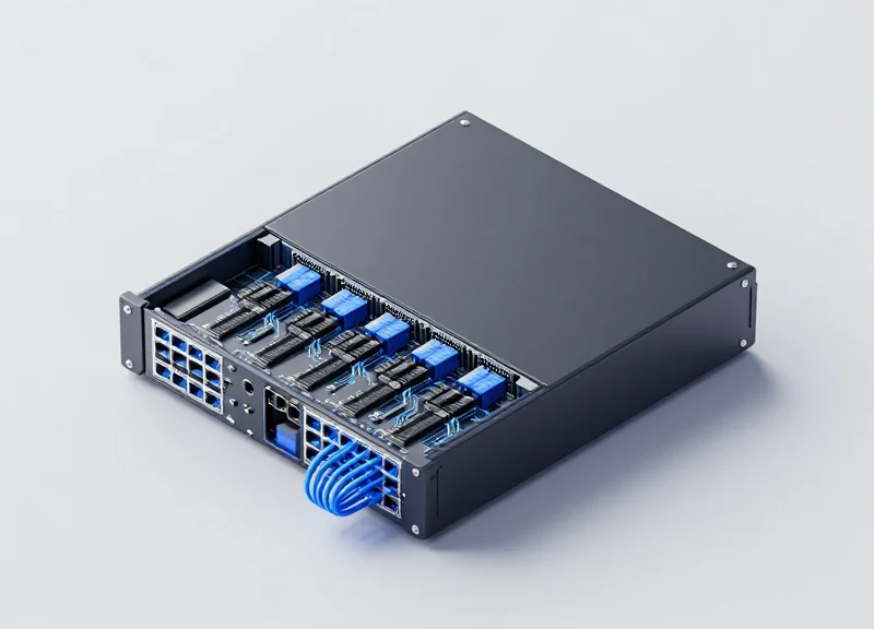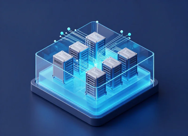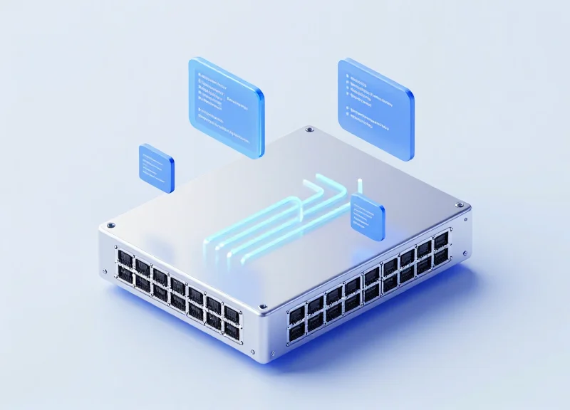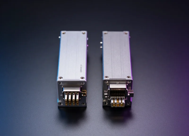
As data centers transition to 800G speeds to meet the demands of AI and high-performance computing, traditional air cooling is reaching its physical limits. 800G optics generate unprecedented heat within compact form factors, making liquid immersion cooling the essential solution for maintaining network reliability and performance.
The Evolution of Data Center Cooling: Why Air is No Longer Enough

The Evolution of Data Center Cooling: Why Air is No Longer Enough
The shift toward 800G connectivity marks a paradigm change in data center thermal management because the heat flux of next-generation ASICs and optical modules now exceeds the heat-carrying capacity of air. While air cooling has been the industry standard for decades, it is a poor thermal conductor; liquid immersion cooling offers up to 1,200 times the heat removal efficiency, which is essential for maintaining the integrity of 800G signals and preventing thermal throttling in high-density environments.
From CRAC Units to Thermal Bottlenecks
Historically, data centers managed heat using Computer Room Air Conditioning (CRAC) units and raised-floor architectures. As power requirements grew, the industry adopted hot/cold aisle containment and rear-door heat exchangers. However, these methods are reaching their limit. A standard 800G-enabled rack can easily exceed 50kW to 100kW of power consumption. Attempting to cool these loads with air requires massive fan arrays that consume a disproportionate amount of electricity—often referred to as the 'tax' on compute—and create acoustic levels that are hazardous to hardware and personnel alike.
| Metric | Air Cooling | Liquid Immersion Cooling |
|---|---|---|
| Thermal Conductivity | Low | High (~1200x Air) |
| Typical Max Rack Density | 15kW - 25kW | 100kW+ |
| Partial PUE (Cooling Only) | 1.3 - 1.5 | 1.02 - 1.05 |
| Hardware Lifespan | Lower (due to thermal cycling) | Higher (stable temperatures) |
| Fan Power Consumption | High (10-20% of IT load) | Zero (fans are removed) |
The 800G Thermal Challenge
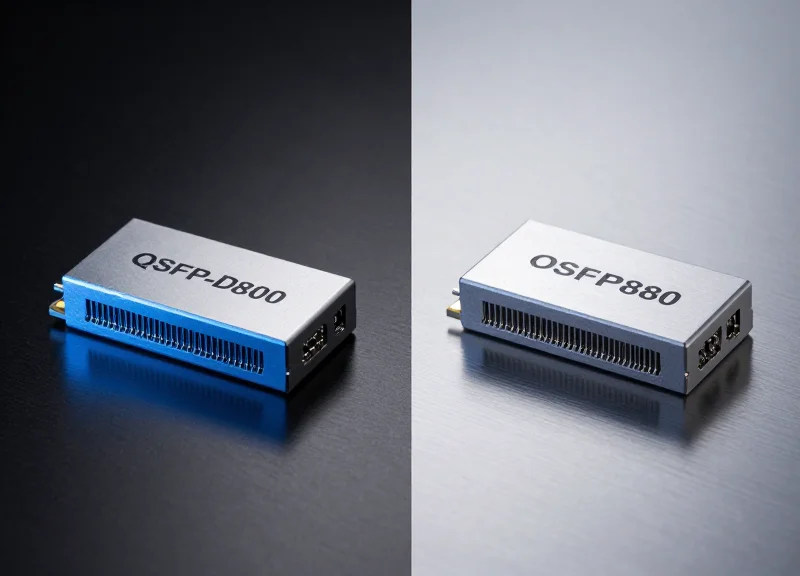
The move to 800G is driven by the need for massive bandwidth in AI and hyperscale clouds. This requires transceivers and switches to pack more transistors into smaller form factors, such as OSFP and QSFP-DD800. These components generate intense localized heat. In an air-cooled system, the air often becomes too hot to effectively cool the second or third row of components in a chassis. Immersion cooling eliminates this 'shadowing' effect by ensuring every component is in direct contact with a dielectric fluid that absorbs heat instantly at the source.
- Why is air cooling failing for 800G hardware?
Air has low specific heat capacity and low thermal conductivity. At 800G densities, the volume of air required to move heat away from high-wattage ASICs is physically larger than the server chassis allows. - What happens if 800G optics run too hot?
Excessive heat leads to laser frequency shifts, increased bit error rates (BER), and shortened Mean Time Between Failures (MTBF), ultimately causing network instability. - Does immersion cooling require special hardware?
Yes, 800G switches and servers must be 'immersion-ready,' meaning fans are removed and thermal pastes are replaced with materials compatible with dielectric fluids.
Thermal Challenges of 800G Optical Transceivers
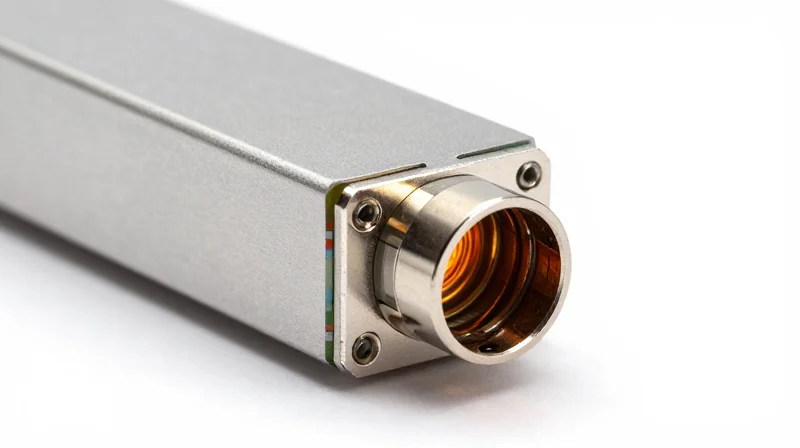
The transition to 800G networking is fundamentally a thermal challenge as much as an electrical one. As data rates climb, the power consumption of the Digital Signal Processor (DSP) and the laser drivers within the pluggable module increases significantly. While 400G modules typically operated within a 10W to 12W envelope, 800G modules—whether in OSFP or QSFP-DD800 form factors—are pushing towards 15W to 25W per port. This concentration of power in a small mechanical volume creates extreme heat flux, making it increasingly difficult to keep internal components within reliable operating temperature ranges using legacy fan-based methods.
Comparing Thermal Envelopes: OSFP vs. QSFP-DD800
| Feature | QSFP-DD800 | OSFP (Octal Small Form-factor Pluggable) |
|---|---|---|
| Typical Power Consumption | 14W - 18W | 16W - 22W |
| Maximum Thermal Design Power | 20W | 25W+ |
| Heat Dissipation Mechanism | Rely on cage/heatsink contact | Integrated fins for improved surface area |
| Heat Flux Density | Extreme (Smaller surface area) | High (Optimized for thermal pathing) |
The Heat Flux Bottleneck and Component Longevity
The core issue at 800G is the thermal resistance between the semiconductor die and the ambient environment. Even with high-velocity airflow, the temperature gradient (Delta T) required to move 20W of heat out of a module often pushes the internal DSP junction temperature toward its maximum limit, usually around 100°C to 105°C. High operating temperatures are the primary driver of 'silent' errors and premature hardware failure. Furthermore, as ambient air temperatures in the data center rise, the cooling capacity of that air diminishes exponentially, leading to thermal throttling where the module reduces its clock speed or power to prevent a catastrophic shutdown.
Thermal FAQs for 800G Deployment
- Why does 800G consume so much more power than 400G?
The move to 112G SerDes and more complex modulation schemes requires higher performance DSPs and increased laser drive currents, which accounts for the nearly 2x jump in wattage. - Can air cooling handle a fully populated 800G switch?
Technically yes, but it requires extreme fan speeds, massive heatsinks, and significant energy overhead, often making the Total Cost of Ownership (TCO) prohibitive compared to liquid alternatives. - What is the impact of heat on optical signal integrity?
Excessive heat causes wavelength drift in the laser and increases noise in the receiver, leading to a higher Bit Error Rate (BER) and potentially dropped packets.
The Mechanics of Immersion Cooling for High-Speed Optics
The Mechanics of Immersion Cooling for High-Speed Optics
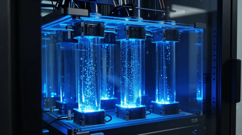
Immersion cooling for 800G hardware operates by submerging the entire electronic assembly—including the switch silicon and the optical transceivers—into a chemically inert, non-conductive dielectric fluid. Unlike air-cooling, which relies on the inefficient movement of gas molecules over heat sinks, immersion cooling facilitates direct liquid-to-chip contact. This allows the coolant to absorb thermal energy directly from the PCB, the Digital Signal Processor (DSP), and the optical engine (TOSA/ROSA) with a heat transfer coefficient that is up to 100 times greater than that of forced air.
Dielectric Fluids vs. Traditional Air Cooling
The primary advantage of immersion cooling lies in the superior thermophysical properties of dielectric fluids. In an 800G environment, where a single rack may house dozens of 25W transceivers, air reaches its physical limit for heat transport. Dielectric fluids, whether used in single-phase (where the liquid remains in a liquid state) or two-phase (where the liquid boils and evaporates) systems, provide a much denser medium for energy evacuation.
| Property | Air (Standard) | Dielectric Fluid (Single-Phase) | Benefit for 800G |
|---|---|---|---|
| Thermal Conductivity (W/m·K) | ~0.026 | 0.06 - 0.15 | Faster heat draw from 800G DSPs |
| Specific Heat Capacity (J/kg·K) | ~1,005 | 1,050 - 1,800 | Higher energy absorption per volume |
| Convective Heat Transfer Coeff. | 10 - 100 | 500 - 2,000 | Massive reduction in component Delta-T |
| Density (kg/m³) | 1.2 | 1,200 - 1,800 | More mass to carry heat away |
Component-Level Interaction in 800G Modules
In a traditional air-cooled 800G setup, the transceiver's metal housing acts as the primary thermal interface. In an immersion environment, the fluid enters the module casing (or the casing is removed/vented) to surround the internal optics directly. This eliminates 'thermal bottlenecks' such as the TIM (Thermal Interface Material) between the chip and the heat sink. By cooling the DSP and laser diodes directly, immersion cooling maintains a lower and more stable operating temperature, which is critical for reducing bit-error rates (BER) and extending the mean time between failures (MTBF) for sensitive 800G laser sources.
- How does the fluid affect optical signal integrity?
Dielectric fluids are designed to be optically transparent and chemically inert. When modules are designed for immersion, the fluid does not interfere with the internal fiber couplings or the electrical signal paths, provided the materials used in the module are compatible with the fluid's chemistry. - Is there a risk of short-circuiting the 800G switch?
No. The fluids used are dielectric, meaning they do not conduct electricity. They have a high dielectric strength, ensuring that even high-frequency electrical signals on the 800G PCB remain isolated and unaffected by the surrounding liquid. - Does immersion require special 800G transceivers?
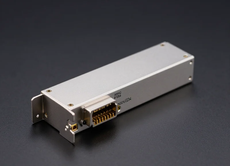
While standard transceivers can be immersed, 'immersion-ready' 800G modules often feature modified housings or removed faceplates to allow better fluid flow over the high-heat components like the DSP.
Single-Phase vs. Two-Phase Immersion Cooling
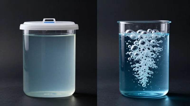
The choice between single-phase and two-phase immersion cooling for 800G hardware is a balance between operational simplicity and the physical limits of heat transfer. Single-phase systems rely on the sensible heat capacity of a liquid that remains in a constant state, making them reliable and easier to maintain for most 800G deployments. In contrast, two-phase systems utilize the latent heat of vaporization, providing significantly higher thermal management capabilities required for the most extreme 800G port densities where traditional convection fails.
Single-Phase Immersion: Convective Stability for 800G
In single-phase immersion cooling, the dielectric fluid (typically a synthetic hydrocarbon or fluorocarbon) is circulated by a pump through the 800G switch chassis. The fluid absorbs heat directly from the ASICs and OSFP/QSFP-DD modules and is then moved to a Coolant Distribution Unit (CDU) to be cooled by a secondary water loop. Because the fluid never reaches its boiling point, the system operates at atmospheric pressure, which simplifies the tank design and reduces the risk of fluid loss through evaporation. For 800G transceivers pulling 15W to 25W, single-phase cooling provides a stable thermal environment with minimal mechanical complexity.
Two-Phase Immersion: Harnessing Latent Heat
Two-phase immersion cooling employs engineered fluids with low boiling points (typically between 34°C and 60°C). When 800G components generate heat, the fluid boils on the surface of the silicon and optical modules, transitioning from liquid to gas. This phase change absorbs massive amounts of energy far more efficiently than liquid convection alone. The resulting vapor rises to the top of the tank, hits a condenser coil, and returns to liquid form. This method is capable of managing heat densities exceeding 100W/cm², making it the premier choice for future-proofing 800G and 1.6T clusters used in AI training.
Comparison of Immersion Technologies for 800G Environments
| Feature | Single-Phase Immersion | Two-Phase Immersion |
|---|---|---|
| Physical State | Liquid only | Liquid to Vapor (Phase Change) |
| Heat Transfer Mechanism | Forced Convection | Latent Heat of Vaporization |
| Fluid Maintenance | Low (Standard filtration) | High (Vapor containment and pressure control) |
| Cooling Capacity | Up to ~100 kW per rack | Exceeding 250 kW per rack |
| 800G Suitability | Optimal for standard 800G switches | Required for high-density AI/HPC clusters |
Operational Considerations and FAQ
- Is fluid loss a significant risk in 800G two-phase systems?
Yes. Because the fluid boils, any seal compromise in the tank can lead to expensive fluid evaporation, whereas single-phase systems are much easier to seal and maintain. - Do 800G transceivers require modifications for immersion?
Generally, transceivers must be 'immersion-ready,' which involves removing unnecessary housing components to allow the fluid to reach the internal optics and PCB. - Which system offers a better PUE for 800G data centers?
Two-phase systems theoretically offer a lower PUE (Power Usage Effectiveness) due to the extreme efficiency of phase-change cooling, though the CAPEX is significantly higher.
Material Compatibility and Dielectric Fluid Specifications
Material compatibility in 800G immersion cooling environments is a multidimensional challenge that bridges chemical stability and high-frequency electrical performance. For 800G systems utilizing PAM4 signaling at high baud rates, the dielectric fluid must not only exhibit superior thermal transfer properties but also remain chemically inert to the specialized polymers, adhesives, and metals found in high-speed optical modules to prevent signal attenuation and physical hardware failure.
Critical Fluid Specifications for High-Frequency Signaling
The primary requirement for fluids in 800G applications is a low dielectric constant (Dk) and a minimal dissipation factor (Df). If a fluid possesses a high Dk, it increases the parasitic capacitance of the PCB traces and transceiver pins, leading to impedance mismatches that can cripple 112G SerDes lanes. Furthermore, the fluid must have high dielectric strength to prevent arcing in the dense pin layouts of QSFP-DD or OSFP form factors.
| Property | Synthetic Hydrocarbons (PAO) | Fluorinated Liquids (PFPE/HFE) |
|---|---|---|
| Dielectric Constant (Dk) | 2.0 - 2.3 | 1.7 - 1.9 |
| Material Compatibility | Risk with EPDM/Silicone | Excellent (Highly Inert) |
| Thermal Conductivity | High (~0.14 W/mK) | Moderate (~0.06 W/mK) |
| Environmental Impact | Low GWP | Variable (High GWP for some) |
Protecting Optical Interconnects and Elastomers
800G transceivers rely on precision-aligned optical lenses and fiber interfaces. A major risk in immersion is 'outgassing' or the leaching of plasticizers from cable jackets and seals into the fluid. These contaminants can deposit on the laser diode faces or lens arrays, causing 'fogging' that increases insertion loss. Additionally, hydrocarbon-based fluids can cause certain elastomers used in transceiver gaskets to swell, potentially compromising the internal hermeticity of the module.
- How does fluid viscosity impact 800G cooling?
Lower viscosity is preferred to ensure the fluid can penetrate the narrow gaps between the module cage and the PCB, facilitating efficient heat removal from internal optical components. - Can immersion fluids damage fiber optic cladding?
Most dielectric fluids are compatible with acrylate-coated fibers, but long-term exposure to certain synthetic oils can cause micro-cracking in specific buffer materials if not properly validated. - What is the 'leaching' effect in immersion systems?
Leaching occurs when the fluid extracts chemical components from PCBs or plastics, which can alter the fluid's dielectric properties and lead to residue buildup on hot 800G ASICs.
Impact on Power Usage Effectiveness (PUE) and Sustainability
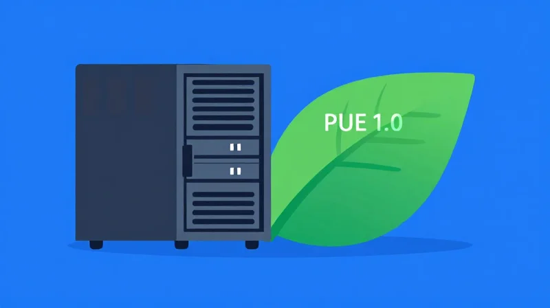
The Shift Toward Ultra-Efficient 800G Infrastructure
The transition to 800G networking introduces unprecedented power densities that challenge the economic and physical limits of traditional air cooling. Immersion cooling addresses this by providing a high-thermal-mass medium that captures nearly 100% of the heat generated by switches and transceivers, enabling a drastic reduction in facility-level energy overhead. By replacing power-hungry CRAC (Computer Room Air Conditioner) units and internal server fans with simple liquid-to-liquid heat exchangers, data centers can achieve a Power Usage Effectiveness (PUE) as low as 1.02 to 1.05, representing a massive leap in operational efficiency over air-cooled counterparts.
Eliminating the 'Fan Tax' and Mechanical Cooling Loads
In a traditional 800G switch chassis, internal fans can consume up to 15% of the total hardware power budget just to move air across dense heatsinks. Immersion cooling allows for the complete removal of these fans, as the dielectric fluid's natural or forced convection handles the thermal load far more effectively. This 'fanless' operation not only reduces the IT power load but also eliminates the energy-intensive process of chilling and humidifying vast volumes of air, which is the primary driver of high PUE in legacy facilities.
| Metric | Legacy Air Cooling (800G) | Immersion Cooling (800G) |
|---|---|---|
| Typical PUE Range | 1.4 - 1.8 | 1.02 - 1.07 |
| Cooling Energy Overhead | 30% - 45% | 3% - 7% |
| Fan Power Consumption | High (10-20% of IT) | Zero (Fans Removed) |
| Water Usage Effectiveness (WUE) | High (Evaporative) | Near Zero (Closed Loop) |
Thermal Recovery and Carbon Reduction
Beyond PUE, immersion cooling enhances sustainability through secondary heat reuse. Because dielectric fluids can operate at higher temperatures (returning fluid at 50°C to 60°C), the waste heat captured is 'high-grade.' This heat is easily transferred to district heating systems or industrial processes, turning a data center's waste into a valuable utility. Furthermore, the increased density allowed by immersion means smaller physical footprints for 800G clusters, reducing the embodied carbon associated with large-scale facility construction.
- How does immersion cooling impact Carbon Usage Effectiveness (CUE)?
By reducing total energy consumption by up to 40% and enabling waste heat recovery, immersion cooling significantly lowers the CO2 emissions per gigabit of data processed, directly improving CUE scores. - Can immersion cooling eliminate the need for water-intensive chillers?
Yes. Most immersion systems utilize dry coolers or closed-loop liquid-to-liquid heat exchangers, which drastically reduce or eliminate water evaporation typical in traditional cooling towers. - What is the ROI on PUE improvements for 800G?
With 800G hardware often drawing 20kW+ per rack, even a 0.1 improvement in PUE results in thousands of dollars in annual energy savings per rack, typically leading to an ROI within 18-24 months.
Design Considerations for Immersion-Ready 800G Hardware
Design Considerations for Immersion-Ready 800G Hardware
Transitioning to 800G networking within an immersion environment demands more than just submerging standard chassis; it requires a fundamental redesign of the physical architecture to leverage the thermal properties of dielectric fluids. Designing for immersion-ready 800G hardware involves stripping away legacy air-cooling components that become redundant or obstructive in a liquid medium, while simultaneously introducing hermetic protection for sensitive optical interfaces to prevent signal distortion.
Mechanical Streamlining and Heatsink Optimization
In an immersion tank, mechanical fans are completely removed, which eliminates a primary source of vibration and mechanical failure. The high-fin-count heatsinks typically found on 800G switch ASICs are also redesigned. Because dielectric fluids have significantly higher heat capacity than air, the dense fin structures required for air cooling can actually impede fluid flow and cause 'boiling entrapment.' Immersion-optimized heatsinks utilize wider spacing or specialized 'boiling enhancement' coatings that facilitate more efficient phase change or convective heat transfer.
Hermetic Sealing of 800G Optical Paths
The most sensitive component in the 800G ecosystem is the optical transceiver. While dielectric fluids are electrically non-conductive, their refractive index is vastly different from air. If fluid enters the optical cavity—the space between the laser source and the fiber interface—it can cause catastrophic signal attenuation and beam misalignment. 800G modules must therefore employ hermetic sealing, often involving glass-to-metal seals or advanced epoxy barriers, to ensure the optical path remains isolated from the coolant while maintaining thermal conductivity.
| Feature | Air-Cooled 800G Hardware | Immersion-Ready 800G Hardware |
|---|---|---|
| Thermal Management | High-RPM fans and dense copper heatsinks | Natural/forced convection or boiling surfaces |
| Optical Transceivers | Open-vented for airflow | Hermetically sealed (IP68+ equivalent) |
| Chassis Structure | Enclosed for airflow direction | Open-frame or perforated for fluid circulation |
| Signal Integrity | Air-gapped trace calculations | Dielectric-compensated trace impedance |
Hardware Adaptation FAQ
- Can standard 800G DAC or AEC cables be used in immersion?
No, standard cable jackets may leach plasticizers into the dielectric fluid. Immersion-ready cables must use FEP, PTFE, or other chemically inert materials to prevent jacket degradation and fluid contamination. - Why is the PCB dielectric constant important?
The fluid fills the microscopic gaps on the PCB. If the board is not designed for a specific dielectric constant, it can shift the impedance of 112G SerDes traces, leading to higher bit error rates (BER). - What happens to the thermal paste on 800G ASICs?
Standard thermal interface materials (TIMs) can wash away in fluid. Immersion-ready hardware uses chemically resistant phase-change materials or metal-based TIMs that stay stable under high-flow liquid conditions.
Operational Reliability and Maintenance in Liquid Environments
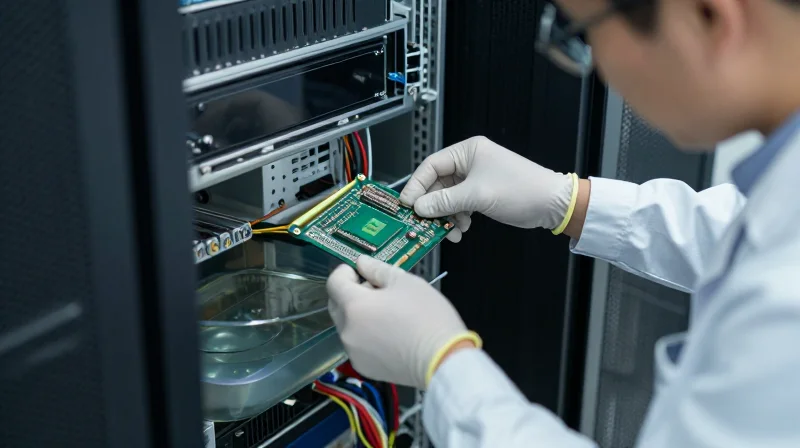
Operational reliability for 800G infrastructure in liquid environments is defined by the stability of the dielectric medium and the precision of component accessibility. Unlike traditional air-cooled racks where fans and filters are the primary failure points, immersion systems demand a focus on fluid purity, material compatibility, and leak-proof hot-swapping procedures. To ensure 24/7 uptime for 800G optics and switches, operators must adopt a lifecycle approach that treats the coolant as a critical system component rather than a passive environment.
Fluid Chemistry and Purity Management
The dielectric fluid used in immersion cooling—whether synthetic hydrocarbons or fluorinated liquids—must maintain specific chemical properties to protect 800G signaling integrity. Over time, 'leachables' from cables or sealants can contaminate the fluid, potentially altering its dielectric constant or causing residue buildup on optical interfaces. Continuous filtration systems and periodic fluid analysis are mandatory to detect moisture ingress or particulate accumulation that could lead to signal attenuation or localized hotspots.
The 'Wet' Maintenance Lifecycle: Hot-Swapping 800G Hardware
Servicing 800G hardware while submerged requires specialized tools such as service trolleys with integrated drip trays and lifting mechanisms. Hot-swapping a blade or a high-density switch involves extracting the hardware slowly to allow fluid to drain back into the tank, minimizing 'drag-out' (fluid loss). For 800G transceivers, ensuring the optical lens remains free of bubbles or fluid residue during re-insertion is critical; many operators utilize specialized 'alignment shrouds' to maintain a clean interface between the fiber and the transceiver in a submerged state.
| Maintenance Task | Air-Cooled 800G Environment | Immersion-Cooled 800G Environment |
|---|---|---|
| Component Swapping | Direct pull/plug with minimal preparation. | Controlled extraction with drip-dry and fluid recovery steps. |
| Thermal Management | Fan replacement and heatsink dusting. | Heat exchanger cleaning and pump redundancy checks. |
| Contamination Control | HEPA filtration for ambient air. | Chemical analysis and particulate filtration of dielectric fluid. |
| Monitoring Focus | Inlet/Outlet air temperatures. | Fluid pressure, flow rate, and dielectric breakdown voltage. |
Predictive Monitoring for 24/7 Uptime
To achieve carrier-grade reliability, immersion systems for 800G utilize a suite of sensors that monitor more than just temperature. Flow meters ensure that the liquid is moving at the correct velocity to dissipate the 30W+ thermal load of 800G transceivers, while moisture sensors provide early warning of heat exchanger leaks. Predictive algorithms analyze pump vibrations and pressure drops across filters to schedule maintenance before a performance-degrading event occurs.
Operational FAQ: Immersion Maintenance
- Does dielectric fluid need to be replaced regularly?
Most high-quality dielectric fluids are designed to last the 10-15 year lifespan of the data center, provided that filtration systems are maintained and contamination is prevented. - Can 800G transceivers be swapped while the system is live?
Yes, provided the system is designed for hot-swapping. The fluid is non-conductive, so there is no risk of short circuits; however, care must be taken to avoid air bubble entrapment on optical faces. - How is fluid loss prevented during maintenance?
Operators use 'clean-room' style extraction protocols and specialized tanks with secondary containment to capture and recycle any fluid that clings to removed hardware.
Future-Proofing: From 800G to 1.6T and Beyond
Future-proofing through immersion cooling transforms the data center from a rigid, air-constrained environment into a fluid and scalable ecosystem capable of handling the 2x to 4x increases in power density expected in the next five years. By removing the 'thermal ceiling' imposed by air, immersion allows for the seamless integration of 1.6T and 3.2T optics, where heat flux levels reach a point where traditional copper heatsinks and high-RPM fans simply cannot move air fast enough to prevent silicon degradation.
Comparing Thermal Demands Across Networking Generations
| Metric | 800G (Current) | 1.6T (Emerging) | 3.2T (Future) |
|---|---|---|---|
| Typical TDP per Module | 15W - 25W | 30W - 45W | 60W - 80W |
| Heat Flux Density | Moderate | High | Extreme |
| Air Cooling Feasibility | Challenging / High Fan Speed | Marginal / Liquid Required | Physically Impossible |
| Cooling Strategy | Single-phase Immersion | Optimized Fluid Flow | Two-Phase / Direct-to-Chip |
Infrastructure Longevity and Investment Protection
One of the primary advantages of an immersion-first approach is the decoupling of hardware refresh cycles from facility cooling upgrades. While networking switches and optical transceivers typically follow a 3-to-5-year lifecycle, the infrastructure of an immersion system—including tanks, heat exchangers, and primary fluid loops—is designed for a 10-to-15-year lifespan. By over-provisioning the thermal capacity of the liquid today, operators can swap 800G switches for 1.6T or 3.2T counterparts with minimal changes to the primary cooling system, drastically lowering future capital expenditure.
Enabling the Move to Co-Packaged Optics (CPO)
As the industry moves toward 3.2T, the transition to Co-Packaged Optics (CPO) or Near-Packaged Optics (NPO) becomes inevitable to manage signal integrity and power efficiency. Immersion cooling is the ideal companion for CPO because it provides a uniform thermal environment across the entire silicon interposer. This prevents the localized hot spots and thermal gradients that plague air-cooled high-density designs, ensuring that sensitive optical paths remain aligned and performance remains consistent under heavy workloads.
Future-Proofing FAQ
- Will 1.6T optics require different immersion fluids?
Most high-performance dielectric fluids used for 800G are capable of handling 1.6T loads, although fluid flow rates and pump speeds may be increased to maintain optimal temperatures. - Can current immersion tanks support 100kW+ per rack?
Yes, immersion tanks are inherently designed for high density. The liquid medium can absorb significantly more heat than air, making 100kW racks a reality for future 3.2T networking. - How does immersion impact signal integrity for future modules?
By maintaining a constant temperature, immersion cooling reduces wavelength drift and thermal noise, which are critical for maintaining the tight signal tolerances required for 1.6T and beyond.
Immersion cooling is no longer an experimental luxury; it is a fundamental requirement for the 800G era. By adopting this technology, organizations can achieve higher density, lower costs, and superior reliability. Ready to optimize your high-speed network for the future? Contact our engineering team to explore our immersion-compatible 800G solutions today.