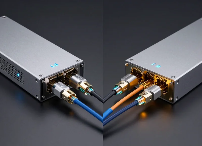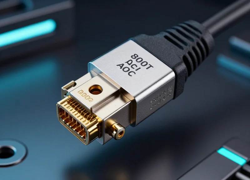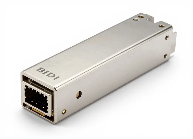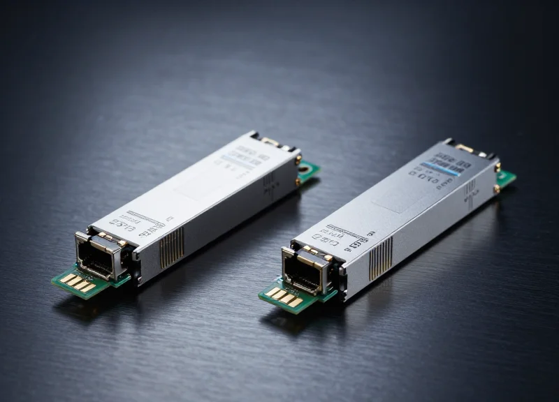
As network demands surge and fiber installation costs rise, network engineers are turning to Bidirectional (BIDI) transceivers to maximize existing infrastructure. By utilizing a single strand of fiber for both transmission and reception, BIDI technology offers a strategic solution to fiber scarcity and operational efficiency. This guide dives deep into the mechanics, benefits, and deployment strategies of BIDI optics.
What is a BIDI Transceiver?
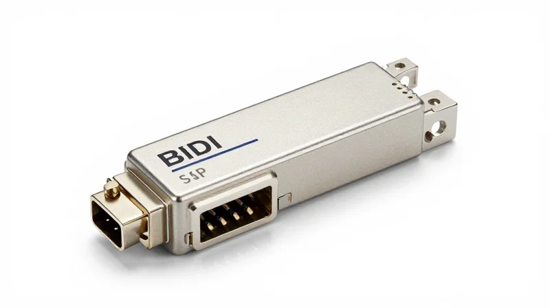
What is a BIDI Transceiver?
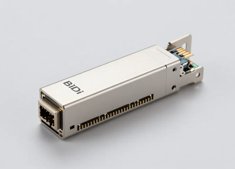
A Bidirectional (BIDI) transceiver is an optical communication module that enables two-way traffic over a single strand of optical fiber. Unlike traditional transceivers that utilize two separate fibers—one for transmitting (TX) and one for receiving (RX)—BIDI technology integrates both functions into a single port. By using Wavelength Division Multiplexing (WDM) couplers, these transceivers combine different wavelengths to send and receive data simultaneously without interference. This technology is primarily used to optimize fiber infrastructure, allowing operators to maximize the utility of existing cable runs or reduce the cost of new fiber deployments by 50%.
The Engineering Behind Single-Fiber Communication
The core of a BIDI transceiver is the Bidirectional Optical Sub-Assembly (BOSA). While a standard transceiver uses a TOSA (Transmitter) and a ROSA (Receiver) separately, the BOSA combines a laser diode, a photodiode, and a specialized WDM filter. This filter acts as a 'traffic controller,' directing specific wavelengths of light. For example, in a common 1G SFP BIDI setup, one module transmits at 1310nm and receives at 1490nm, while its partner on the opposite end does the exact inverse. This wavelength offset is what prevents signal collisions on the shared glass medium.
| Feature | Traditional Dual-Fiber Transceiver | BIDI Single-Fiber Transceiver |
|---|---|---|
| Fiber Count | Two strands (Duplex) | One strand (Simplex) |
| Wavelengths | Typically identical for TX/RX | Different wavelengths for TX/RX (e.g., 1270/1330nm) |
| Hardware Pairing | Identical modules on both ends | Requires matched pairs (Side A and Side B) |
| Cost Efficiency | Lower module cost, higher cabling cost | Higher module cost, 50% lower cabling cost |
Common Questions About BIDI Technology
- Must BIDI transceivers be used in pairs?
Yes. Because BIDI transceivers use different wavelengths for transmitting and receiving, you must use a 'matching' pair. If the local module transmits at 1310nm and receives at 1550nm, the remote module must transmit at 1550nm and receive at 1310nm. - Can I use standard patch cables with BIDI modules?
Yes, BIDI transceivers are compatible with standard single-mode fiber (SMF) patch cords, provided the connectors match (usually LC or SC). The main difference is that you only connect one strand instead of two. - What are the most common wavelength pairs?
Common pairings include 1310nm/1490nm and 1310nm/1550nm for shorter distances, and 1270nm/1330nm for high-speed 10G, 25G, or 40G applications using BiDi technology.
The Science of Wavelength Division Multiplexing (WDM)
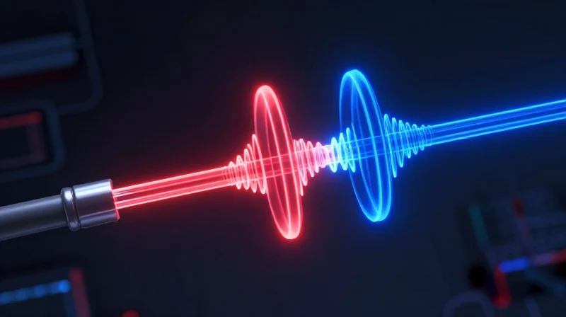
The Science of Wavelength Division Multiplexing (WDM)
Wavelength Division Multiplexing (WDM) is the foundational technology that enables Bidirectional (BIDI) transceivers to defy the traditional two-strand fiber requirement. In standard fiber optics, data travels like a one-way street, necessitating one fiber for the transmit (TX) path and another for the receive (RX) path. WDM changes this dynamic by multiplexing multiple optical carrier signals onto a single optical fiber by using different wavelengths (colors) of laser light. By assigning specific, non-overlapping wavelengths to the upstream and downstream signals, BIDI optics create two virtual lanes of traffic within a single physical glass core, effectively doubling the bandwidth efficiency of the installed fiber plant.
The Role of the Optical Diplexer
The critical hardware component inside a BIDI transceiver that facilitates WDM is the optical diplexer. Unlike a standard transceiver that has separate ports for TX and RX, a BIDI transceiver features a single port coupled to a Bidirectional Optical Sub-Assembly (BOSA). The diplexer acts as a frequency-selective filter, directing the outgoing laser light into the fiber while simultaneously reflecting the incoming light of a different wavelength toward the receiver diode. This precise filtering ensures that the transmitted signal does not 'blind' the sensitive receiver, maintaining high signal integrity even as data flows in both directions at once.
| BIDI Transceiver Type | Upstream Wavelength (TX) | Downstream Wavelength (RX) |
|---|---|---|
| 1G SFP BIDI | 1310 nm | 1490 nm |
| 1G SFP BIDI (Alternative) | 1490 nm | 1310 nm |
| 10G SFP+ BIDI | 1270 nm | 1330 nm |
| 10G SFP+ BIDI (Alternative) | 1330 nm | 1270 nm |
| 25G SFP28 BIDI | 1270 nm | 1310 nm |
Understanding Wavelength Pairings
To establish a functional link, BIDI transceivers must be deployed in matched pairs, often referred to as 'Side A' and 'Side B'. If the transceiver at Site A transmits at 1310nm and receives at 1490nm, the transceiver at Site B must do the exact opposite—transmit at 1490nm and receive at 1310nm. This complementary pairing is essential; using two identical BIDI transceivers at both ends will result in a link failure because both devices would be attempting to transmit and receive on the same frequencies, leading to signal collision and total loss of communication.
- Does WDM technology cause signal latency?
No, the use of different wavelengths through WDM does not introduce measurable latency. The light still travels at the speed of light through the glass medium, and the diplexer's filtering is near-instantaneous. - Can 1310/1550nm pairings be used with 1270/1330nm?
No. The optical filters in the BIDI transceivers are hard-coded to specific wavelength windows. Mixing different wavelength standards will result in the receiver being unable to 'see' the incoming light. - How does BIDI prevent 'crosstalk' between signals?
Crosstalk is prevented by the high isolation of the internal thin-film filters (TFF) within the BOSA, which ensures that only the target wavelength reaches the receiver photodiode while the transmitted wavelength is blocked.
Internal Components: The BOSA Advantage

Internal Components: The BOSA Advantage
The Bidirectional Optical Sub-Assembly (BOSA) is the engineering marvel that makes BIDI transceivers possible by merging the traditionally separate Transmitter Optical Sub-Assembly (TOSA) and Receiver Optical Sub-Assembly (ROSA) into a single, integrated housing. This consolidated design uses a precision-aligned wavelength division multiplexing (WDM) filter to manage the dual paths of light, allowing a single optical port to handle both incoming and outgoing data simultaneously without internal interference.
The Anatomy of a BOSA Unit
Inside the BOSA, several critical components work in unison within a hermetically sealed environment. The primary components include a Laser Diode (LD) for signal transmission, a Photodiode (PD) for signal reception, and a WDM filter (typically a 45-degree dichroic mirror). The filter acts as a traffic controller: it allows the specific transmit wavelength to pass through to the fiber connector while reflecting the incoming receive wavelength toward the photodiode. This spatial separation is achieved with sub-micron precision to ensure high coupling efficiency and minimal signal loss.
| Component/Feature | Standard Dual-Fiber (TOSA + ROSA) | BIDI (Single BOSA) |
|---|---|---|
| Housing Configuration | Two separate metallic canisters | Single integrated assembly |
| Optical Interface | Two ports (TX and RX) | One port (Bi-directional) |
| Wavelength Management | Physically separate fibers | Internal 45-degree WDM filter |
| Alignment Complexity | Moderate | High (Requires precise filter placement) |
Miniaturization and Signal Integrity
The BOSA advantage extends beyond just saving fiber; it also enables the miniaturization of network equipment. By reducing the physical footprint of the optical engine, manufacturers can maintain standard SFP/SFP+ form factors while doubling port density in high-traffic environments. Furthermore, because the TX and RX components are so close together, BOSA designs must incorporate advanced electrical shielding to prevent 'crosstalk'—a phenomenon where the high-power transmit signal creates electromagnetic interference in the sensitive receiver circuit.
BOSA Implementation FAQ
- How does BOSA prevent the transmit laser from blinding its own receiver?
This is achieved through the internal WDM filter and optical isolators. The filter is specifically coated to only reflect the target receive wavelength toward the photodiode, while the transmit wavelength passes straight through, effectively isolating the two paths. - Is a BOSA more susceptible to heat than separate TOSA/ROSA units?
Because components are densely packed, thermal management is critical. High-quality BOSAs utilize heat sinks and specific materials to dissipate heat away from the laser diode to ensure wavelength stability and longevity. - Can a BOSA handle different speeds like 10G or 25G?
Yes, BOSA technology is scalable. While early versions were common in 1G speeds, modern BOSA assemblies are now standard in 10G SFP+, 25G SFP28, and even some higher-speed bidirectional applications.
Strategic Advantages of Single-Fiber Solutions
Strategic Advantages of Single-Fiber Solutions
Deploying BIDI transceivers fundamentally changes the economics of network infrastructure by leveraging a single strand of fiber for full-duplex communication. This shift translates directly into a 50% reduction in cabling infrastructure requirements, enabling network operators to double their capacity without the prohibitive costs of installing new physical fiber plants. By optimizing the physical layer, organizations can achieve greater scalability and operational agility in high-density environments.
Substantial Reduction in Capital Expenditure
The most immediate benefit of BIDI technology is the direct reduction in Capital Expenditure (CapEx). In traditional dual-fiber setups, every link requires two strands of fiber—one for transmitting and one for receiving. BIDI optics collapse these functions into a single strand, which is particularly critical when fiber resources are scarce or when leasing fiber by the strand. For greenfield projects, this means purchasing half as much cable; for brownfield projects, it means doubling capacity without digging new trenches.
| Metric | Traditional Dual-Fiber | BIDI Single-Fiber |
|---|---|---|
| Fiber Strands per Link | 2 Strands | 1 Strand |
| Infrastructure Cost | 100% (Baseline) | ~50% (Cable Only) |
| Patch Panel Density | Standard | 2x Density |
| Cable Management | Complex/Bulky | Simplified/Thin |
Space Optimization and Data Center Airflow
In modern high-density data centers, physical space in cable trays and patch panels is a finite resource. Reducing the number of patch cords by 50% leads to significantly less congestion in the racks. This reduction in 'cable spaghetti' not only simplifies installation and troubleshooting but also improves thermal management. Fewer cables blocking the rear of the server chassis allow for better airflow, which can lead to lower cooling costs and improved hardware longevity.
Simplified Management and ROI Analysis
- How does BIDI impact long-term ROI?
BIDI transceivers provide a faster Return on Investment by deferring the need for expensive fiber plant expansions. By doubling the utility of existing glass, organizations can scale their bandwidth at the cost of the transceivers alone, rather than the much higher cost of civil engineering and fiber deployment. - Does single-fiber use simplify patch management?
Yes. With 50% fewer connectors to clean, test, and label, the operational man-hours required for maintenance are drastically reduced. It also minimizes the risk of 'flipped' fiber pairs, a common error in dual-fiber installations where the TX and RX strands are swapped incorrectly. - Is BIDI more effective for leased fiber scenarios?
Absolutely. For Metropolitan Area Networks (MANs) where fiber is often leased from a third party on a per-strand basis, BIDI allows a provider to run two separate services over the same leased pair, effectively halving their monthly recurring costs (OpEx).
Deployment Flexibility
Single-fiber solutions provide unparalleled flexibility for emergency capacity upgrades. When a fiber bundle reaches full utilization, BIDI transceivers can be swapped in to immediately free up half of the existing strands. These reclaimed strands can then be repurposed for redundancy, additional data channels, or specialized services, providing a strategic 'buffer' for network architects planning for unpredictable growth.
The Complementary Pair Rule: TX vs. RX
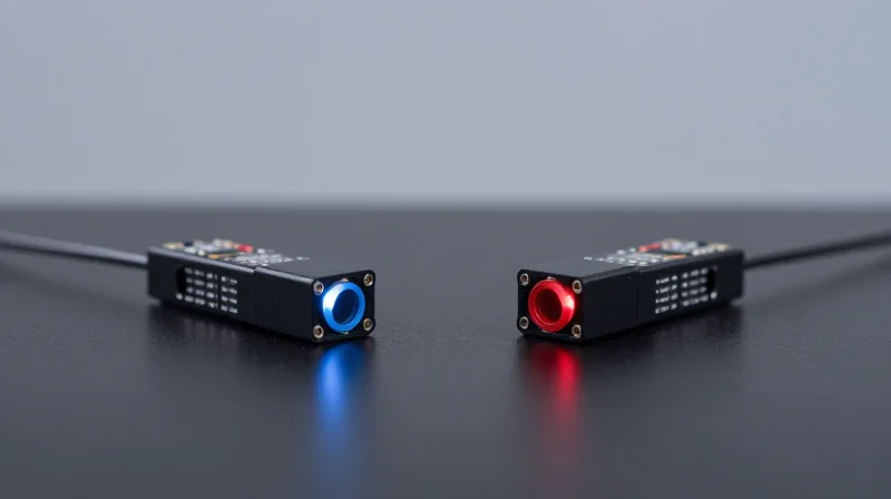
The Complementary Pair Rule: Transmit (TX) Must Match Receive (RX)
For a BIDI (Bidirectional) transceiver to function, it must be deployed as part of a 'matched pair' where the transmit (TX) wavelength of Module A perfectly aligns with the receive (RX) wavelength of Module B. Unlike standard dual-fiber transceivers that use identical modules at both ends of a link, BIDI modules are wavelength-specific. If Side A is transmitting at 1310nm and receiving at 1490nm, the remote Side B must do the exact opposite: transmit at 1490nm and receive at 1310nm. Failure to follow this symmetry results in a 'dark link,' as the photodiodes will not be tuned to the frequency of the incoming light.
Nomenclature: Understanding Upstream (U) and Downstream (D)
To simplify procurement and installation, manufacturers typically categorize BIDI modules into 'A' and 'B' sides, or 'Upstream' (U) and 'Downstream' (D) versions. This nomenclature ensures that network engineers do not accidentally install two identical modules on the same link. For example, in 10G SFP+ BIDI deployments, you will frequently see modules labeled as 1270nm-TX/1330nm-RX (the 'U' or 'A' side) and 1330nm-TX/1270nm-RX (the 'D' or 'B' side). Identifying these pairs is the first step in successful single-fiber provisioning.
| Common Standard | Module Side A (TX/RX) | Module Side B (TX/RX) | Primary Use Case |
|---|---|---|---|
| 1G SFP BIDI | 1310nm / 1490nm | 1490nm / 1310nm | FTTH / Access Networks |
| 10G SFP+ BIDI | 1270nm / 1330nm | 1330nm / 1270nm | Enterprise / Data Centers |
| 25G SFP28 BIDI | 1270nm / 1310nm | 1310nm / 1270nm | 5G Wireless Front-haul |
| 1G SFP BIDI (Long Haul) | 1310nm / 1550nm | 1550nm / 1310nm | Metro/Campus Links |
Deployment Best Practices and Troubleshooting
- Can I use two 'Side A' modules together?
No. If both modules transmit at 1310nm, they will interfere with each other if there is any reflection, but more importantly, neither module's receiver (tuned to 1490nm) will see the 1310nm signal. The link will not initialize. - How are BIDI pairs identified physically?
Most vendors use color-coded bail latch handles or clear labeling on the transceiver sticker. For instance, a blue latch might represent 1310nm TX, while a purple or yellow latch might represent 1490nm or 1550nm TX. - Do I need special fiber optic cabling for BIDI pairs?
No. BIDI transceivers use standard Simplex LC or SC patch cords. The complexity of splitting the wavelengths is handled entirely inside the BOSA (Bidirectional Optical Sub-Assembly) within the transceiver housing. - Is there a performance difference between the two sides?
Generally, no. While different wavelengths (like 1310nm vs 1550nm) have slightly different attenuation profiles over very long distances, BIDI pairs are calibrated to ensure the link budget is met for the rated distance (e.g., 10km, 20km, or 40km) regardless of which end is A or B.
Common Form Factors and Speed Graduations
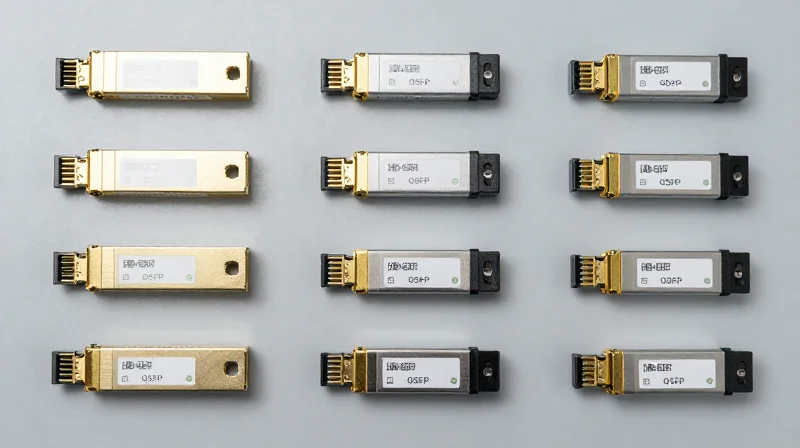
The Spectrum of BIDI Form Factors and Speeds
BIDI transceivers have evolved from specialized niche components into mainstream networking staples, now available in every major industry form factor to support data rates from 1Gbps to 100Gbps. By leveraging Wavelength Division Multiplexing (WDM), these modules enable bidirectional communication over a single strand of fiber, ensuring that as network speeds increase, the physical infrastructure requirements remain lean and cost-effective.
1G SFP and 10G SFP+ BIDI Solutions
The Small Form-factor Pluggable (SFP) and SFP+ remain the most ubiquitous deployments for BIDI technology. 1G SFP BIDI modules are widely used in Fiber-to-the-Home (FTTH) and enterprise access layers, typically employing 1310/1490nm or 1310/1550nm wavelength pairs. 10G SFP+ BIDI modules serve as the backbone for many campus networks and metro Ethernet links, offering distances ranging from 10km to 80km.
High-Speed Evolution: 25G SFP28 and 100G QSFP28
To keep pace with 5G wireless fronthaul and data center demands, BIDI technology has moved into higher speed graduations. 25G SFP28 BIDI transceivers are critical for 5G deployments where fiber resources are scarce. At the top tier, 100G QSFP28 BIDI modules utilize sophisticated PAM4 modulation and multi-wavelength architectures (such as 100G-BiDi which uses two 50Gbps channels) to deliver massive throughput over a single fiber pair or single strand depending on the specific standard.
| Form Factor | Data Rate | Common Wavelengths (TX/RX) | Standard Reach |
|---|---|---|---|
| SFP BIDI | 1.25 Gbps | 1310/1490nm, 1310/1550nm | 10km - 160km |
| SFP+ BIDI | 10 Gbps | 1270/1330nm, 1490/1550nm | 10km - 80km |
| SFP28 BIDI | 25 Gbps | 1270/1330nm | 10km - 40km |
| QSFP+ BIDI | 40 Gbps | 850/900nm (Multi-mode) | 100m - 150m |
| QSFP28 BIDI | 100 Gbps | 1270/1330nm (Single-mode) | 10km - 40km |
Common Questions on BIDI Speed Graduations
- Can I use 10G BIDI SFPs in 1G SFP ports?
Generally, no. While some multi-rate SFPs exist, most BIDI transceivers are fixed-rate. The port must support the specific data rate and the transceiver must match the speed of the remote end. - Is 100G BIDI standardized across all vendors?
100G BIDI often follows the MSA (Multi-Source Agreement) standards like 100G-BiDi. While many vendors follow these, it is crucial to ensure both ends of the link use compatible wavelength pairs and modulation types (like PAM4). - Does higher speed reduce the maximum reach of BIDI modules?
Yes, typically as speed increases, signal integrity becomes more sensitive to dispersion and attenuation. While 1G BIDI can reach 160km, 100G BIDI is currently optimized for 10km to 40km ranges.
Real-World Applications: From FTTH to 5G

BIDI transceivers serve as the primary catalyst for cost-effective fiber expansion in high-demand sectors, enabling service providers to double their bandwidth capacity without the prohibitive expense of laying new physical fiber cables. By utilizing Wavelength Division Multiplexing (WDM), these modules facilitate simultaneous upstream and downstream communication over a single strand, which is a fundamental requirement for the rapid, dense rollout of FTTH and 5G wireless architectures.
Scaling Fiber-to-the-Home (FTTH) and PON Deployments
In the context of Fiber-to-the-Home (FTTH), BIDI technology is a cornerstone of Passive Optical Network (PON) architectures. Traditionally, residential broadband required separate fibers for transmitting and receiving data, which quickly depleted available duct space in urban environments. BIDI transceivers allow ISPs to connect twice as many subscribers using the same fiber count. This efficiency is particularly visible in the transition to XGS-PON and beyond, where 10G BIDI modules ensure that high-speed symmetrical internet can be delivered over existing single-strand infrastructure.
Empowering 5G Wireless Fronthaul Networks
The shift to 5G has introduced the Cloud Radio Access Network (C-RAN) architecture, which necessitates high-bandwidth connections between the Remote Radio Unit (RRU) and the Building Baseband Unit (BBU). Because 5G requires significantly more base stations than 4G, fiber resources are under immense pressure. 25G BIDI SFP28 transceivers have emerged as the industry standard for 5G fronthaul, providing the necessary 25Gbps throughput over a single fiber to meet eCPRI requirements while minimizing the complexity of fiber management at the cell site.
| Application Area | Common Form Factor | Typical Wavelengths | Primary Advantage |
|---|---|---|---|
| FTTH / PON | SFP / SFP+ | 1310nm / 1490nm | Doubles subscriber density per fiber strand |
| 5G Fronthaul | SFP28 | 1270nm / 1330nm | Reduces fiber cabling costs by 50% at cell sites |
| Campus Backbones | SFP / SFP+ | 1310nm / 1550nm | Simplifies link troubleshooting and patch management |
| Data Centers | QSFP28 | 1270nm / 1330nm | Optimizes rack space and cable tray congestion |
Application Specifics and Deployment FAQ
- Can BIDI transceivers be used for long-haul carrier networks?
Yes, BIDI modules are available in specialized configurations like ER (Extended Range) and ZR (Zephyr Range), supporting distances up to 40km or 80km, making them suitable for regional metro links. - Why is 1270nm/1330nm preferred for 5G over 1310nm/1550nm?
The 1270/1330nm window offers lower dispersion for 25G speeds over the shorter distances typical of 5G fronthaul, ensuring better signal integrity for high-frequency mobile data. - Are BIDI transceivers compatible with standard patch panels?
Absolutely. They use standard LC or SC simplex connectors, allowing them to integrate into existing patch panels, provided the fiber is single-mode.
Future Outlook: 100G BIDI and Beyond
As bandwidth demands continue to escalate, the industry is moving toward 100G BIDI solutions using QSFP28 form factors. These are increasingly deployed in data center interconnects (DCI) and core ISP nodes, proving that the single-fiber efficiency model is scalable from residential access all the way to the heart of the global internet backbone network clouds.
Installation Best Practices and Troubleshooting
Best Practices for BiDi Transceiver Installation
Successful BiDi (Bidirectional) transceiver installation is predicated on the 'Complementary Pairing' principle, ensuring that the transmit (TX) wavelength of Side A perfectly matches the receive (RX) wavelength of Side B. Unlike standard duplex fiber where cables can often be 'flipped' to fix polarity issues, BiDi links require specific, non-interchangeable hardware at each end of the single fiber strand to function.
Cleaning and Handling Procedures
Because BiDi technology utilizes a single simplex port for both transmission and reception, the internal diplexer is extremely sensitive to back-reflections. Even microscopic dust particles on the connector end-face can cause light to bounce back into the receiver, significantly increasing the Bit Error Rate (BER). Installers should follow the 'Inspect-Clean-Inspect' workflow using a fiber microscope and a high-quality click-cleaner before every insertion.
Diagnostic Power Level Monitoring
Digital Optical Monitoring (DOM) is an essential tool for troubleshooting BiDi links. It allows network administrators to view real-time data regarding temperature, supply voltage, and—most importantly—optical TX and RX power levels. Identifying a mismatch between the expected power budget and the actual DOM reading is the first step in diagnosing a faulty fiber plant or a failing optic.
| Parameter | Typical Healthy Range | Troubleshooting Indicator |
|---|---|---|
| TX Power | -3 to -9 dBm (10G LR) | Low TX indicates laser degradation or failing transceiver hardware. |
| RX Power | -1 to -14 dBm | High RX (>-1) indicates saturation; Low RX (<-15) indicates fiber loss or dirty connectors. |
| Temperature | 0°C to 70°C (Commercial) | Excessive heat often points to poor switch ventilation or port overcrowding. |
Troubleshooting Common 'No Link' Scenarios
- Why is the link light off even though the fiber is connected?
The most common cause is a wavelength mismatch. Ensure you have paired a 'U' (Upstream) module with a 'D' (Downstream) module. For example, if Side A is 1310nm-TX/1490nm-RX, Side B must be 1490nm-TX/1310nm-RX. - How do I diagnose a 'Signal Loss' alarm in the switch console?
Check the fiber patch cable first. Since BiDi uses simplex LC connectors, ensure the cable is fully seated. If the error persists, use an Optical Power Meter (OPM) calibrated to the specific BiDi wavelength to verify that light is reaching the end of the run. - Can I use a BiDi transceiver with a standard duplex patch cord?
No. BiDi transceivers require a simplex (single fiber) patch cord. Attempting to use a duplex cable will result in an unconnected strand and a failed link, as the transceiver only has one optical port. - What should I do if the RX power is too high?
BiDi modules, especially 'ER' or 'ZR' long-reach variants, can saturate the receiver over short distances. If DOM reports high RX power, insert an optical attenuator (e.g., 5dB or 10dB) to prevent permanent damage to the photodiode.
Future Trends in Bi-Directional Optical Networking
Scaling to 400G, 800G, and Beyond
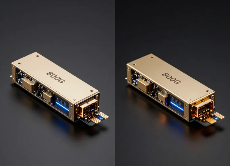
As global data consumption continues to explode, BIDI transceivers are evolving from the traditional 10G and 25G standards into 400G and 800G form factors. This evolution is driven by the urgent need to maximize fiber plant efficiency in hyperscale environments where laying new fiber is either physically impossible or prohibitively expensive. By utilizing PAM4 (Pulse Amplitude Modulation 4-level) and advanced Wavelength Division Multiplexing (WDM) on a single strand, network operators can quadruple their existing capacity without installing additional infrastructure.
Silicon Photonics: The Integration Catalyst
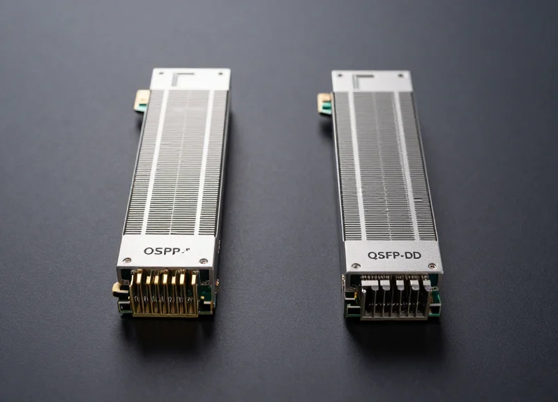
Silicon photonics is the cornerstone of future BIDI development. By integrating laser sources, modulators, and detectors directly onto a silicon chip using standard CMOS processes, manufacturers can significantly reduce the physical size and power consumption of BIDI transceivers. This integration is essential for high-density QSFP-DD and OSFP form factors, allowing for complex internal Bi-Directional Optical Sub-Assemblies (BOSA) that can handle multiple wavelengths on a single fiber with minimal crosstalk and thermal overhead.
| Generation | Typical Speed | Key Technology | Primary Use Case |
|---|---|---|---|
| Legacy BIDI | 1G - 25G | NRZ Modulation | FTTx, Basic Enterprise |
| Current BIDI | 100G | PAM4, Silicon Photonics | 5G Fronthaul, Data Centers |
| Next-Gen BIDI | 400G - 800G+ | Coherent Detection, Integrated SiPh | Hyperscale DCI, 6G Preparation |
Coherent BIDI for Metro and Long-Haul
While BIDI has historically been associated with short to medium-reach applications, the introduction of coherent BIDI transceivers is changing the landscape. Coherent technology allows for high-order modulation and sophisticated digital signal processing (DSP) to compensate for chromatic and polarization-mode dispersion. This enables 100G or even 400G BIDI links to span 80km or more over a single fiber strand, providing a cost-effective and simplified solution for Metro-Ethernet and Data Center Interconnects (DCI) where fiber lease costs are high.
Future Outlook FAQ
- Why is 800G BIDI necessary?
It addresses the massive bandwidth requirements of AI clusters and cloud computing while halving the required fiber cabling, which reduces complexity and cooling requirements in the data center. - How does silicon photonics impact BIDI costs?
By utilizing semiconductor manufacturing techniques, silicon photonics lowers production costs at scale and improves yield compared to traditional discrete optical packaging. - Will BIDI eventually replace dual-fiber transceivers?
While it may not replace them entirely for every niche, BIDI is increasingly becoming the preferred choice for greenfield deployments and capacity-constrained brownfield fiber plants due to its 50% fiber savings.
BIDI transceivers represent one of the most effective ways to scale network capacity without the prohibitive costs of laying new fiber. By understanding the technical nuances of WDM and proper pair matching, you can significantly enhance your network's efficiency and longevity. Ready to optimize your infrastructure? Contact our engineering team today for a custom BIDI solution consultation.