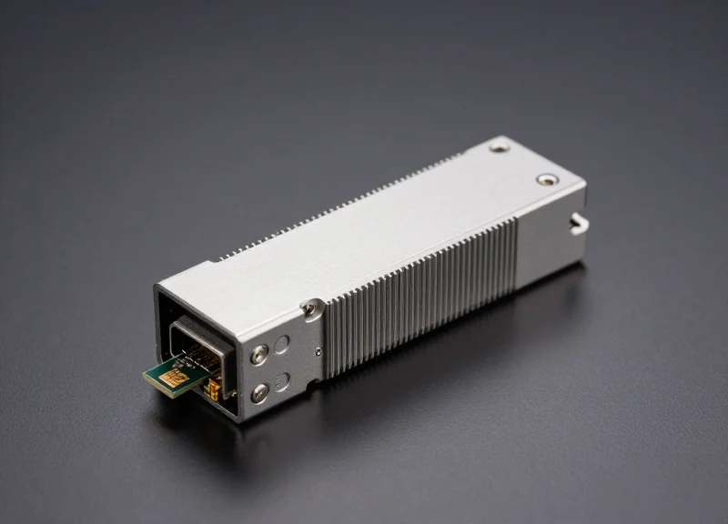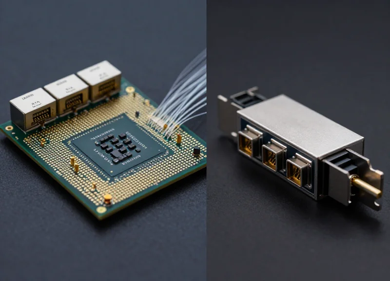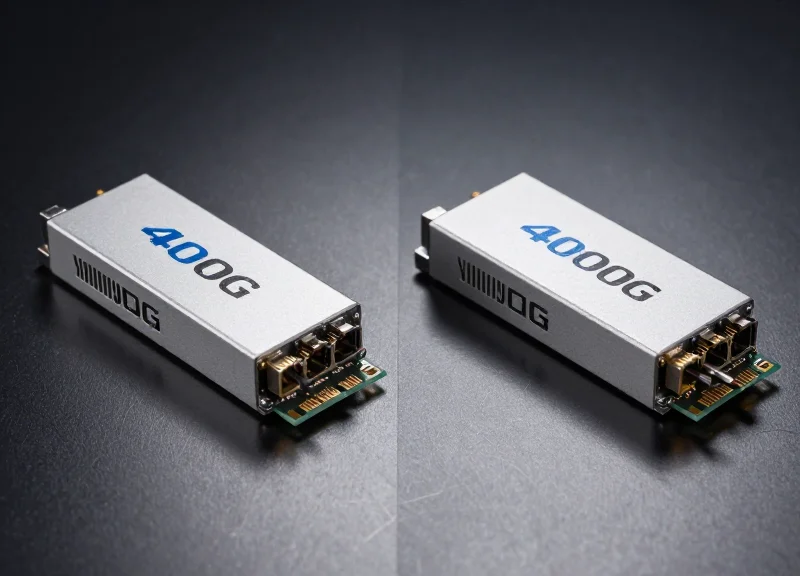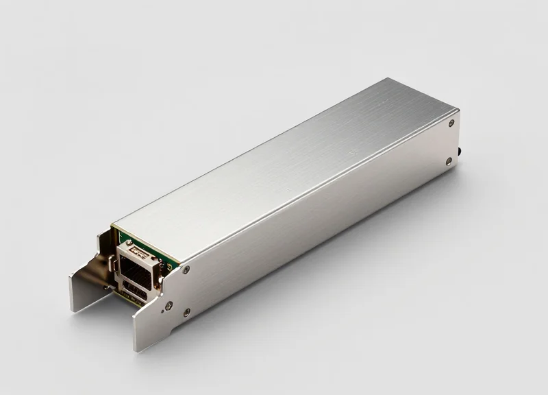
As global data traffic grows exponentially, the 400G QSFP-DD DR4 transceiver has become a critical building block for high-density optical interconnects. This article provides an authoritative technical breakdown of its architecture, performance metrics, and role in next-generation network scaling.
The Fundamentals: Defining 400G QSFP-DD DR4
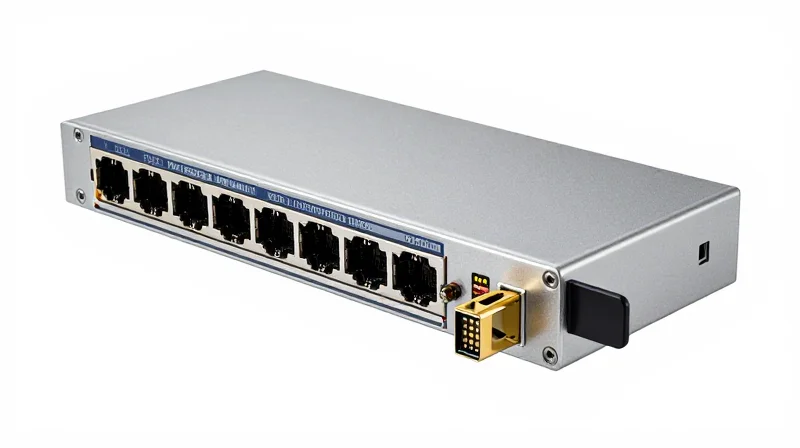
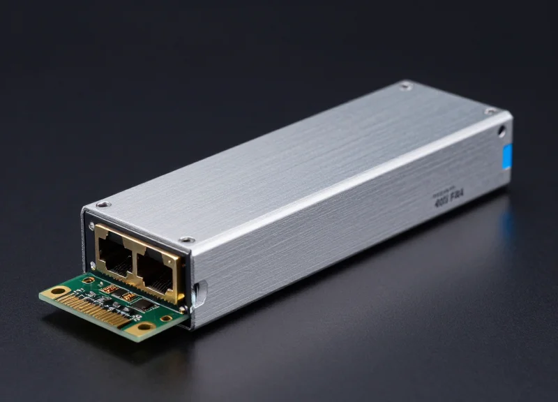
The 400G QSFP-DD DR4 is a high-speed optical transceiver designed for high-density 400 Gigabit Ethernet applications, utilizing the Double Density form factor to provide an eight-lane electrical interface while employing the 'Data Center Reach 4' standard to transmit data over four parallel channels of single-mode fiber (SMF) up to 500 meters.
Deconstructing the Nomenclature: QSFP-DD
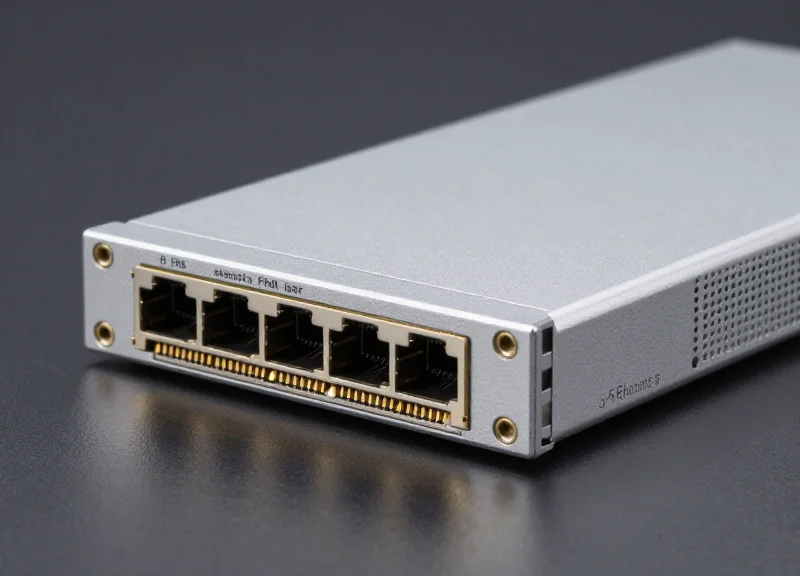
The 'QSFP-DD' acronym stands for Quad Small Form-factor Pluggable Double Density. This interface represents a critical evolution in networking hardware, designed to address the bandwidth requirements of hyperscale data centers. By adding a second row of electrical contacts to the traditional QSFP architecture, the 'Double Density' variant increases the number of electrical lanes from four to eight. This design allows for a 400G aggregate throughput (8 lanes x 50Gbps PAM4) while maintaining a physical footprint small enough to support 32 to 36 ports in a single 1RU switch chassis.
Defining the 'DR4' Optical Standard
The 'DR4' suffix specifies the optical characteristics and the reach of the module. 'DR' stands for Datacenter Reach, a standard optimized for short-distance transmissions up to 500 meters over Single Mode Fiber (SMF). The number '4' indicates that the module uses four parallel optical lanes rather than multiplexing signals over a single pair. Each of these four lanes operates at 100Gbps using PAM4 modulation, requiring an MPO-12 (or MPO-8) connector to manage the parallel fiber strands.
| Naming Component | Technical Definition | Functional Role |
|---|---|---|
| QSFP | Quad Small Form-factor Pluggable | Defines the standardized mechanical shell and power envelope. |
| DD | Double Density | Doubles the electrical lanes from 4 to 8 for 400G support. |
| DR | Datacenter Reach | Specifies 500m reach over Single Mode Fiber (SMF). |
| 4 | 4 Parallel Lanes | Indicates 4x100G parallel transmission via MPO connectors. |
Common Questions Regarding 400G DR4 Fundamentals
- Is QSFP-DD DR4 backward compatible?
Yes, the QSFP-DD port is designed to be backward compatible with legacy QSFP28 and QSFP+ modules, allowing operators to migrate to 400G incrementally. - What modulation does 400G DR4 use?
It utilizes PAM4 (Pulse Amplitude Modulation 4-level) to pack more data into each clock cycle compared to traditional NRZ signaling. - Why use 4 lanes (DR4) instead of 1 lane?
Using four parallel 100G lanes allows for lower complexity and cost per bit compared to achieving a single-lane 400G optical signal at this distance.
Optical Architecture and Parallel Design
Optical Architecture and Parallel Design
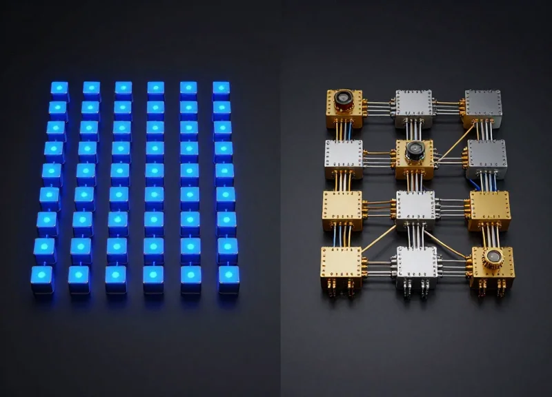
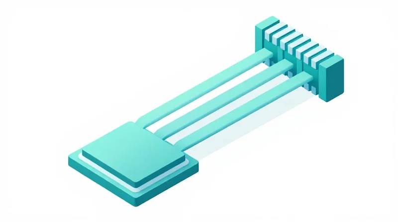
The architecture of the 400G QSFP-DD DR4 is defined by its use of Parallel Single Mode (PSM) technology, which distributes the 400Gbps aggregate bandwidth across four discrete spatial channels. Unlike Wavelength Division Multiplexing (WDM) solutions that combine multiple signals onto a single fiber pair, the DR4 standard utilizes eight individual fibers—four for transmission and four for reception—to maintain high signal integrity over distances up to 500 meters.
The 4x100G PAM4 Modulation Scheme
At the heart of the DR4's optical engine is 100G PAM4 (4-level Pulse Amplitude Modulation) technology. The electrical interface consists of eight lanes of 50Gbps (GAUI-8), which are processed by an internal Digital Signal Processor (DSP) and Gearbox to drive four optical lanes at 100Gbps each. By using a single wavelength (typically 1310nm) across all four parallel fibers, the DR4 avoids the cost and complexity of optical multiplexers and demultiplexers, significantly reducing the thermal footprint of the transceiver.
| Feature | 400G QSFP-DD DR4 | 400G QSFP-DD FR4 |
|---|---|---|
| Optical Technique | Parallel Single Mode (PSM4) | CWDM (Wavelength Multiplexing) |
| Fiber Count | 8 Fibers (4 Tx, 4 Rx) | 2 Fibers (1 Tx, 1 Rx) |
| Connector Type | MPO-12 / MTP-12 (APC) | LC Duplex |
| Reach | 500 Meters | 2 Kilometers |
The MPO Interface and Breakout Potential
The physical interface of the 400G DR4 employs an MPO-12 or MPO-8 Angled Physical Contact (APC) connector. This parallel design is strategically advantageous for data center operators because it supports breakout applications. Using a 1x4 breakout cable, a single 400G DR4 port can connect directly to four independent 100G DR transceivers. This capability is essential for high-density leaf-spine architectures, enabling seamless scaling between different tiers of the network.
- Why is an APC (Angled Physical Contact) connector required?
PAM4 modulation is highly sensitive to optical return loss. The 8-degree angle on APC connectors ensures that reflected light is absorbed into the cladding rather than reflecting back into the laser source, maintaining signal stability. - Can DR4 work over existing 12-fiber MPO cabling?
Yes, it typically uses the four outermost fiber pairs of an MPO-12 connector (Fibers 1-4 and 9-12), leaving the center four fibers unused, making it compatible with standard MPO-12 infrastructure. - What is the primary benefit of the DR4 architecture over FR4?
The primary benefit is lower latency and reduced cost per port for short-reach applications, alongside the unique ability to break out into four 100G links.
PAM4 Modulation and the Role of DSP

PAM4 Modulation and the Role of DSP
The transition to 400G QSFP-DD DR4 marks a fundamental shift in signal encoding, moving from binary Non-Return-to-Zero (NRZ) to four-level Pulse Amplitude Modulation (PAM4). By utilizing four distinct signal levels to represent two bits of data per symbol, PAM4 effectively doubles the network capacity within the same physical bandwidth. This spectral efficiency is the cornerstone of 400G technology, allowing the DR4 standard to achieve 100Gbps per lane over four parallel fibers without requiring prohibitively high clock speeds.
The Mechanics of PAM4 vs. NRZ
While NRZ uses two voltage levels (high and low) to signify a '1' or '0', PAM4 introduces four levels: 00, 01, 10, and 11. This creates three 'eyes' in the signal diagram rather than one. While this increases density, it significantly reduces the Signal-to-Noise Ratio (SNR) because the voltage gaps between levels are much smaller. Consequently, PAM4 signals are far more susceptible to noise, jitter, and inter-symbol interference, necessitating sophisticated processing to ensure data accuracy.
| Feature | NRZ (100G Legacy) | PAM4 (400G DR4) |
|---|---|---|
| Bits per Symbol | 1 bit | 2 bits |
| Signal Levels | 2 (Low, High) | 4 (0, 1, 2, 3) |
| Signal-to-Noise Ratio | High | Low (-9.5 dB relative to NRZ) |
| Primary Limitation | Bandwidth constrained | Noise and Complexity constrained |
The DSP: The 'Brain' of the QSFP-DD DR4
To combat the inherent fragility of PAM4 signals, the 400G QSFP-DD DR4 module incorporates a powerful Digital Signal Processor (DSP). The DSP acts as the high-speed engine that cleans, retimes, and amplifies signals as they pass between the electrical interface of the switch and the optical lanes of the transceiver. It utilizes adaptive equalization algorithms, such as Feed-Forward Equalization (FFE) and Decision Feedback Equalization (DFE), to compensate for transmission impairments and ensure the 'eyes' of the PAM4 signal remain open for accurate sampling.
- Why is a DSP required for 400G DR4?
The DSP is essential for PAM4 because it mitigates the high Bit Error Rate (BER) caused by reduced signal levels, performing clock data recovery (CDR) and electronic dispersion compensation. - How does the DSP manage Forward Error Correction (FEC)?
The DSP works in tandem with the host's FEC (typically KP4 FEC for DR4) to detect and correct bit errors that occur due to optical noise, ensuring reliable link performance. - What is the impact of the DSP on power consumption?
The DSP is the most power-hungry component in a QSFP-DD module, contributing significantly to the 12W power envelope required for 400G operations compared to legacy 100G NRZ modules.
Key Performance Specifications
Key Performance Specifications of 400G QSFP-DD DR4
The performance of a 400G QSFP-DD DR4 module is dictated by its adherence to the IEEE 802.3bs and QSFP-DD MSA standards, ensuring interoperability across diverse networking hardware. Its primary function is to support high-bandwidth transmission up to 500 meters using parallel single-mode fiber (PSM4) architecture. By operating at a nominal wavelength of 1310nm, the DR4 module minimizes chromatic dispersion, which is essential for maintaining signal clarity at 100Gbps per lane speeds over the designated distance.
| Parameter | Specification Detail |
|---|---|
| Form Factor | QSFP-DD (Quad Small Form-factor Pluggable Double Density) |
| Data Rate | 425 Gbps (8x50G PAM4 Electrical / 4x100G PAM4 Optical) |
| Wavelength | 1310nm (Center Wavelength) |
| Maximum Reach | 500 Meters over SMF (G.652) |
| Optical Connector | MPO-12/APC or MPO-8/APC |
| Modulation Type | PAM4 (Pulse Amplitude Modulation 4-level) |
| Power Consumption | Typically <12W (Class 3 or 4) |
| Operating Temperature | 0°C to 70°C (Commercial Grade) |
Power Consumption and Thermal Management
In hyperscale environments, power efficiency is as vital as throughput. The 400G QSFP-DD DR4 module is engineered to operate within a strict power envelope, usually staying below 12 Watts. This is achieved through the integration of highly efficient 7nm or 5nm Digital Signal Processors (DSPs). Managing the thermal output of these modules is critical; if power consumption exceeds the cooling capacity of the switch chassis, it can lead to bit error rate (BER) degradation or hardware failure. Advanced firmware within the module provides real-time Digital Optical Monitoring (DOM) to track temperature, voltage, and bias current.
Link Budget and Signal Integrity
The optical link budget for a DR4 transceiver is relatively tight, typically around 3.0 to 4.0 dB. This budget must account for fiber attenuation, connector insertion loss (especially in MPO environments), and various penalties such as TDECQ (Transmitter and Dispersion Eye Closure Quaternary). To ensure reliable data recovery, the module utilizes Forward Error Correction (FEC), specifically KP4 FEC, which is mandatory for 400G operation to correct errors and achieve a post-FEC BER of less than 1E-15.
- Does 400G DR4 support breakout applications?
Yes, because it uses 4 parallel lanes of 100G, a DR4 module can be broken out into four individual 100G DR or 100G FR connections using a breakout cable. - Why is 500m the standard reach for DR4?
The 500m limit is optimized for intra-data center 'leaf-to-spine' connections where distances rarely exceed half a kilometer, allowing for lower-cost optics compared to 2km (FR4) or 10km (LR4) variants. - What fiber type is required?
It requires Single-Mode Fiber (SMF) with an MPO-12 APC (Angled Physical Contact) connector to prevent back-reflections that could interfere with the PAM4 signal.
The Power of Breakout: 400G to 4x100G
Enabling High-Density Interoperability via Breakout Modes
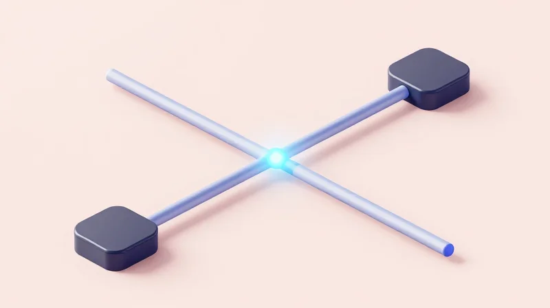
The 400G QSFP-DD DR4 is engineered for maximum architectural flexibility, functioning as a high-density gateway that facilitates the transition from 100G to 400G fabrics. Unlike single-lane serial modules, the DR4 utilizes four parallel optical lanes, each carrying 100Gbps using PAM4 modulation. This specific design allows a single 400G port to be 'broken out' into four independent 100G DR1 interfaces. This backward compatibility is vital for data center operators who need to connect newer 400G spine switches to existing 100G leaf switches or high-performance servers without requiring immediate forklift upgrades of the entire infrastructure.
Optimizing Leaf-Spine Architecture
In a leaf-spine network topology, the ability to split 400G ports significantly increases port density and reduces the physical footprint of the interconnect hardware. By using an MPO-to-LC breakout cable, the four parallel lanes of the DR4 are separated into four duplex LC connectors. Because the 400G DR4 and the 100G DR1 both operate at the 1310nm wavelength and share identical modulation schemes, they achieve native optical interoperability over distances up to 500 meters. This synergy ensures that signal integrity is maintained across the breakout, providing a reliable, low-latency path for tiered data center traffic.
| Feature | 400G QSFP-DD DR4 (Breakout) | 100G QSFP28 DR1 |
|---|---|---|
| Wavelength | 1310nm | 1310nm |
| Modulation | 100G PAM4 (per lane) | 100G PAM4 |
| Fiber Connector | MPO-12 or MPO-8 | Duplex LC |
| Transmission Type | 4-Lane Parallel | Single Lane |
| Maximum Reach | 500m | 500m |
Breakout Strategy FAQ
- Can 400G DR4 connect to 100G FR1 modules?
Yes. While DR1 is rated for 500m and FR1 for 2km, they are optically compatible at the 1310nm wavelength. As long as the link distance does not exceed the 500m limit of the DR4, these modules can interoperate in a breakout configuration. - What specific cabling is required for a DR4 breakout?
A 12-fiber or 8-fiber MPO (Female) to 4 x Duplex LC breakout cable is required. This cable maps the eight fibers (four transmit, four receive) of the DR4 to four separate 100G optical paths. - Does the switch software need to be configured for breakout?
Yes. Most Network Operating Systems (NOS) require the port to be manually configured into 'breakout mode' (e.g., 4x100G) to ensure the internal SerDes lanes are mapped correctly for four independent signals.
QSFP-DD Form Factor: Density and Compatibility
QSFP-DD: The Foundation of High-Density 400G Networking
The Quad Small Form-factor Pluggable Double Density (QSFP-DD) is a critical evolution in optical interconnects, designed specifically to meet the bandwidth demands of hyper-scale data centers. By doubling the number of electrical lanes from four to eight, the QSFP-DD DR4 module achieves a total bandwidth of 400Gbps within a physical footprint similar to its predecessors. This design choice allows network operators to maximize front-panel density, supporting up to 36 ports of 400G in a single 1RU switch chassis, effectively providing 14.4Tbps of total throughput.
The 8-Lane Electrical Interface
The primary innovation of the QSFP-DD is the 'Double Density' aspect. While a standard QSFP28 module features a single row of electrical contacts to support 4 lanes, the QSFP-DD adds a second row of contacts behind the first. This creates an 8-lane electrical interface (8x50G PAM4), allowing for twice the data throughput. Because the 400G DR4 module converts these eight electrical signals into four optical lanes of 100Gbps each via its internal DSP, the electrical density is the engine that makes 400G transmission possible.
Backward Compatibility and Mechanical Design
One of the most significant advantages of the QSFP-DD form factor is its backward compatibility. A QSFP-DD port on a switch or router is designed to accept legacy QSFP modules, including QSFP+ (40G), QSFP28 (100G), and QSFP56 (200G). When a legacy module is inserted, it only engages the first row of electrical contacts, and the system automatically adjusts to the lower lane count. This protects existing infrastructure investments and allows for a phased migration to 400G.
| Feature | QSFP28 (100G) | QSFP-DD (400G) |
|---|---|---|
| Electrical Lanes | 4 Lanes | 8 Lanes |
| Modulation | NRZ or PAM4 (50G) | PAM4 (50G/100G) |
| Max Power | Up to 5W | Up to 12W - 15W |
| Port Density | Standard | Double (14.4T per 1RU) |
Thermal Management Challenges
Operating eight lanes of high-speed electronics alongside a power-hungry DSP creates significant thermal challenges. 400G DR4 modules typically consume between 10W and 12W of power. Dissipating this heat in a high-density switch environment requires sophisticated thermal design. QSFP-DD address this through improved cage designs and integrated heat sinks. Effective airflow management is essential to prevent thermal throttling, which can degrade signal integrity or lead to component failure in fully populated 400G line cards.
- Can I use a 400G QSFP-DD DR4 module in a QSFP28 port?
No. While QSFP-DD ports are backward compatible with QSFP28 modules, a QSFP-DD module cannot be physically inserted into a QSFP28 port because of its longer depth and the extra row of electrical contacts. - Does the 8-lane interface affect the optical fiber connection?
The 8 lanes refer to the electrical side (to the switch). On the optical side, the DR4 uses 4 lanes (MPO-12 connector) to transmit data over parallel single-mode fibers. - Why is density so important for 400G?
High density reduces the footprint and power-per-bit in the data center, allowing for massive scaling without requiring additional physical space or excessive cooling infrastructure.
400G DR4 vs. FR4 vs. LR4: Choosing the Right Reach
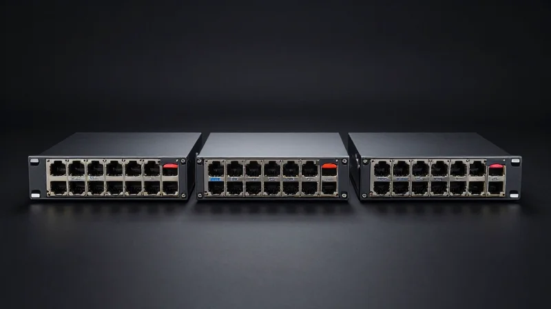
Choosing between 400G DR4, FR4, and LR4 depends primarily on the required link distance and the existing fiber infrastructure, where DR4 is the standard for 500m breakout-capable links using parallel fiber, while FR4 and LR4 leverage duplex fiber for 2km and 10km spans respectively. While all three modules utilize the QSFP-DD form factor, their internal optics and lane configurations are tailored for specific tiers of the data center hierarchy, from leaf-spine connections to campus-wide interconnects.
Comparative Analysis: DR4 vs. FR4 vs. LR4
| Feature | 400G DR4 | 400G FR4 | 400G LR4 |
|---|---|---|---|
| Max Reach | 500 Meters | 2 Kilometers | 10 Kilometers |
| Fiber Type | Single-Mode (Parallel) | Single-Mode (Duplex) | Single-Mode (Duplex) |
| Connector | MPO-12/MPO-8 | Duplex LC | Duplex LC |
| Wavelength | 1310nm | CWDM4 (1271-1331nm) | LWDM4 (1295-1309nm) |
| Main Use Case | Intra-Data Center / Breakout | Leaf-Spine / Campus | DCI / Long-Haul Campus |
Strategic Selection Criteria
The 400G DR4 is uniquely positioned for operators who require high-density breakout capabilities. Because it uses four independent 100G lanes over parallel fiber, it allows a single 400G port to connect directly to four 100G DR1 transceivers. This makes it the most flexible choice for top-of-rack to spine connections where short-distance migration is key. However, for links extending beyond 500m, the cost of parallel fiber cabling becomes prohibitive.
For distances up to 2km, the 400G FR4 is the industry favorite. It uses Coarse Wavelength Division Multiplexing (CWDM) to aggregate four 100G channels onto a single pair of fibers. By utilizing duplex LC connectors, it significantly reduces the complexity and cost of the physical cabling plant compared to DR4 for long-run leaf-spine architectures. For even longer reaches, the LR4 uses LAN-WDM technology with tighter wavelength spacing to ensure signal integrity over 10km, though this comes at the cost of higher power consumption and price points.
Frequently Asked Questions
- Can I connect a 400G DR4 to a 400G FR4?
No. They use different optical configurations (parallel vs. multiplexed) and different connector types (MPO vs. LC), making them fundamentally incompatible for direct connection. - Why would I choose LR4 over FR4 if my distance is only 1.5km?
You generally wouldn't. FR4 is more cost-effective and consumes less power for links under 2km. LR4 should be reserved for links that strictly exceed the 2km limit or require higher link budgets due to patch panel losses. - Does DR4 require special cabling?
Yes, it requires 8-fiber or 12-fiber MPO (Single-mode) cabling. This is different from the standard LC duplex cables used by FR4 and LR4.
Deployment Scenarios in Hyperscale Data Centers

The 400G QSFP-DD DR4 transceiver is a cornerstone of modern hyperscale infrastructure, specifically designed to address the bandwidth density requirements of massive east-west traffic patterns. By utilizing four parallel lanes of 100G PAM4 over single-mode fiber, it allows network architects to maximize port utilization on high-radix switches while maintaining a low power-per-bit ratio, essential for scaling out flattened network topologies.
Spine-Leaf Architecture and Breakout Applications
In a typical Tier-1 hyperscale data center, the 400G DR4 module serves as a critical bridge between 400G spine switches and 100G leaf switches. Using an MPO-12 to 4x LC breakout cable, a single 400G port can support four independent 100G DR1 links. This breakout capability is vital for tiered migrations, allowing operators to upgrade their core fabric to 400G without necessitating an immediate, wholesale replacement of all 100G top-of-rack (ToR) hardware. This flexibility significantly reduces initial capital expenditure while providing a clear path to full 400G saturation.
Short-Reach Data Center Interconnect (DCI)
While often associated with intra-rack connectivity, the 500-meter reach of the DR4 standard makes it highly effective for short-reach Data Center Interconnect (DCI) within a single building or across small campus environments. In these scenarios, the primary focus is on minimizing latency and power consumption. Unlike 400G FR4 or LR4, which use Coarse Wavelength Division Multiplexing (CWDM) to multiplex signals onto a single pair of fibers, DR4 uses parallel fibers. This eliminates the need for complex multiplexing/demultiplexing optics, which helps maintain a leaner power profile and minimizes the thermal footprint in high-density rack environments.
| Deployment Scenario | Typical Distance | Fiber Type | Key Advantage |
|---|---|---|---|
| Intra-Fabric (Spine-Leaf) | Up to 500m | SMF (MPO-12) | Enables 4x100G breakouts to legacy leaf switches |
| Campus DCI | 100m - 500m | SMF (Parallel) | Low latency and reduced optical complexity |
| High-Radix Core Switching | <100m | SMF | Maximum port density for 400G-to-400G links |
Operational Efficiency and Latency Considerations
In hyperscale environments, latency is often the bottleneck for distributed AI training and high-frequency financial applications. The 400G QSFP-DD DR4 minimizes latency by utilizing a straightforward parallel mapping of electrical lanes to optical lanes. Because the module avoids the processing overhead of complex multiplexing, the signal path remains exceptionally clean. Furthermore, the use of single-mode fiber (SMF) ensures that the deployment is 'future-proofed,' as the fiber plant remains compatible with future 800G and 1.6T iterations that will likely continue to leverage parallel SMF architectures.
Deployment FAQ
- Why is DR4 preferred over copper DACs for 400G spine links?
While Direct Attach Copper (DAC) cables are cheaper, their reach at 400G is limited to approximately 2.5 meters. DR4 provides the 500m reach necessary to traverse the height and length of large hyperscale data halls. - Can 400G DR4 modules interoperate with 100G DR1?
Yes, this is one of the primary deployment drivers. Through an MPO-to-LC breakout, one 400G DR4 port can talk directly to four 100G DR1 transceivers, facilitating a phased network upgrade. - Does DR4 require a specific type of connector?
Yes, 400G DR4 typically uses an MPO-12 or MPO-8 connector to facilitate the four parallel fiber pairs (eight fibers total) required for its operation.
Ensuring Interoperability and Quality Control
Reliability in 400G networks hinges on the standardization of electrical and optical parameters, ensuring that transceivers from diverse manufacturers can operate harmoniously within a single fabric. For the 400G QSFP-DD DR4, this interoperability is governed by two primary frameworks: the IEEE 802.3bs standard, which defines the physical layer specifications for 400 Gb/s Ethernet, and the QSFP-DD Multi-Source Agreement (MSA), which standardizes the mechanical, electrical, and management interfaces. Adherence to these standards prevents vendor lock-in and ensures that the 500-meter reach over parallel single-mode fiber is achieved with a consistent link budget and power efficiency.
The Pillars of Standardization: IEEE and MSA
| Standardization Body | Primary Focus | Key DR4 Specification |
|---|---|---|
| IEEE 802.3bs | Optical & Physical Layer | Defines 400GBASE-DR4 optical parameters and PAM4 signaling. |
| QSFP-DD MSA | Form Factor & Interface | Standardizes 76-pin electrical connectors and thermal management. |
| CMIS (Common Management) | Software Interoperability | Provides a unified register map for module diagnostics and control. |
| OIF CEI-56G-VSR | Electrical Signaling | Specifies the host-to-module electrical interface characteristics. |
Critical Metrics for Quality Control
Quality control for 400G DR4 modules involves rigorous testing of PAM4-specific metrics. Unlike traditional NRZ signaling, PAM4 requires the measurement of TDECQ (Transmitter and Dispersion Eye Closure Quaternary). This metric quantifies the optical power penalty of a real-world transmitter compared to an ideal one; for DR4 compliance, TDECQ must typically remain below 3.4 dB. Furthermore, the Bit Error Rate (BER) must be maintained at a pre-FEC level of less than 2.4e-4 to ensure that the host's Forward Error Correction (FEC) can deliver a virtually error-free post-FEC environment (10^-15).
Interoperability and Deployment FAQ
- Can I mix different brands of 400G DR4 modules in a single link?
Yes. As long as both modules comply with the IEEE 802.3bs 400GBASE-DR4 standard, they are designed to interoperate, even if they are installed in switches from different vendors. - Why is CMIS compliance vital for DR4 modules?
The Common Management Interface Specification (CMIS) ensures that the host switch can correctly initialize, monitor, and troubleshoot the module, regardless of the manufacturer, by using a standardized set of registers. - What happens if a module fails TDECQ testing?
A high TDECQ value indicates poor eye opening in the PAM4 signal, which can lead to excessive bit errors that exceed the recovery capabilities of the KP4 FEC, resulting in link instability or total failure. - How does the MSA impact thermal management?
The QSFP-DD MSA specifies the physical housing and heat sink requirements, ensuring that modules stay within the standard 0-70°C operating temperature range even at 12W+ power levels.
The 400G QSFP-DD DR4 module is a vital asset for any data center aiming for high-bandwidth efficiency and scalability. By understanding its technical nuances, network architects can better prepare for the future of optical networking. Ready to optimize your infrastructure? Contact our experts for a personalized 400G consultation.