As data centers and service providers transition from 100G to 400G, the need for reliable long-distance connectivity has never been more critical. While short-reach solutions dominate intra-rack connections, the 400G LR4 standard emerges as the definitive solution for high-bandwidth links across metropolitan and campus distances. This guide provides a deep dive into the engineering and strategic advantages of 400G LR4.
Understanding the 400G LR4 Standard
Defining the 400G LR4 Standard
400G LR4 is a standardized optical interface designed for 400 Gigabit Ethernet (GbE) that enables high-speed data transmission over distances of up to 10 kilometers using single-mode fiber (SMF). This standard represents a significant shift in optical engineering by employing four independent 100 Gbps channels, modulated via PAM4 (Four-Level Pulse Amplitude Modulation), and multiplexed onto a single fiber pair. It is specifically engineered to bridge the gap between data center interconnects (DCI) and metropolitan area networks, providing the necessary reach for campus backbones and regional service provider links.
Regulatory Foundations: IEEE 802.3bs and 100G Lambda MSA
The 400G LR4 specification is built upon two primary industry frameworks: the IEEE 802.3bs amendment and the 100G Lambda MSA (Multi-Source Agreement). While IEEE 802.3bs defined the initial physical layer requirements for 400 Gbps Ethernet, the 100G Lambda MSA was instrumental in standardizing the use of 100 Gbps single-wavelength optical signals. By leveraging these standards, 400G LR4 reduces the hardware complexity from the older 8-lane (8x50G) configurations used in 400G SR8 or FR8 to a more efficient 4-lane (4x100G) architecture, lowering both power consumption and cost per bit.
| Parameter | Technical Specification |
|---|---|
| Standardization | IEEE 802.3bs / 100G Lambda MSA |
| Maximum Reach | 10 Kilometers |
| Fiber Type | Single-Mode Fiber (SMF/G.652) |
| Modulation Type | PAM4 (53.125 GBd) |
| Wavelength Grid | LAN-WDM (1295.56, 1300.05, 1304.58, 1309.14 nm) |
| Optical Connector | Duplex LC |
Wavelength Allocation and Optical Performance
To achieve 10km reach without signal degradation, 400G LR4 utilizes the LAN-WDM (Local Area Network Wavelength Division Multiplexing) wavelength grid in the O-band. The wavelengths are centered around 1310nm, a region where chromatic dispersion in single-mode fiber is at its lowest. By spacing the four wavelengths narrowly (approximately 800 GHz apart), the standard ensures high spectral efficiency and minimizes the need for complex dispersion compensation. This precision allows for a robust link budget that can withstand the attenuation typical of long-distance campus or metro fiber spans.
- Why is 400G LR4 preferred over 400G DR4 for long distances?
400G DR4 is designed for 500m reaches using parallel fiber (8 fibers total), whereas 400G LR4 uses WDM technology to send 400G over a single fiber pair for up to 10km, making it more fiber-efficient for long-haul cabling. - Does 400G LR4 require Forward Error Correction (FEC)?
Yes, the standard relies on KP4 FEC (as defined in IEEE 802.3bs) to maintain a Bit Error Rate (BER) that ensures reliable data integrity over the 10km distance. - Can 400G LR4 work with existing 100G LR4 infrastructure?
While both use SMF and LC connectors, 400G LR4 uses PAM4 modulation whereas legacy 100G LR4 uses NRZ; therefore, they are not directly interoperable without a gearbox or a compatible multi-rate port.
The Optical Engine: LAN-WDM Technology
The Optical Engine: LAN-WDM Technology
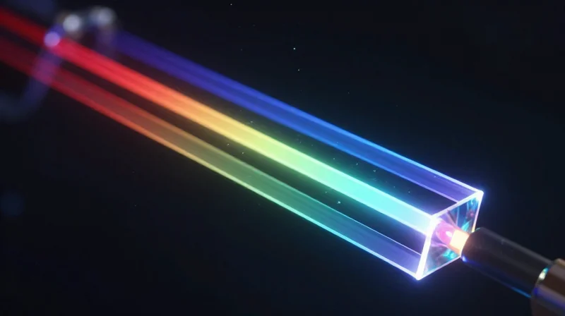
At the core of the 400G LR4 transceiver lies the Local Area Network Wavelength Division Multiplexing (LAN-WDM) optical engine. Unlike short-reach solutions that rely on wide-spaced channels, LAN-WDM utilizes four specific wavelengths centered around the 1310nm zero-dispersion point. By multiplexing four 106.25 Gbps (PAM4) signals into a single fiber, LAN-WDM achieves the high throughput necessary for 400G while maintaining the signal integrity required to traverse up to 10km of single-mode fiber without active dispersion compensation.
The 800GHz Grid and O-Band Precision
LAN-WDM operates on a narrow 800GHz frequency grid, which translates to a wavelength spacing of approximately 4.5nm. The specific wavelengths used are 1295.56nm, 1300.05nm, 1304.58nm, and 1309.14nm. This placement is strategic; by staying within the O-band, the optical signals experience minimal chromatic dispersion. Because the wavelengths are tightly packed, the transceiver requires a Thermo-Electric Cooler (TEC) to maintain temperature stability, ensuring that the lasers do not drift from their assigned frequencies—a level of precision far exceeding standard CWDM solutions.
| Feature | LAN-WDM (400G LR4) | CWDM4 (400G FR4) | |||
|---|---|---|---|---|---|
| Channel Spacing | ~4.5nm (800GHz) | 20nm | |||
| Wavelength Range | 1295nm to 1309nm | 1271nm to 1331nm | |||
| Dispersion Sensitivity | Very Low (O-band center) | Higher (Wider spectrum) | Cooling Requirement | TEC Required (Active) | Uncooled (Passive) |
| Max Distance | 10km | 2km |
Mitigating Dispersion Over Long Distances
The primary challenge in 400G transmission over 10km is Chromatic Dispersion (CD), where different wavelengths travel at different speeds, causing pulse broadening and Bit Error Rate (BER) degradation. The 400G LR4 standard addresses this by confining the LAN-WDM grid to the region where the dispersion slope of G.652 single-mode fiber is flattest. This ensures that the PAM4 symbols remain distinct and recoverable at the receiver end, even at high baud rates, without the latency penalties often associated with heavy digital signal processing for dispersion correction.
- Why is LAN-WDM used instead of CWDM for 10km?
CWDM's 20nm spacing spans a wider range of the O-band where dispersion increases significantly. LAN-WDM's narrow 4.5nm spacing keeps all channels near the zero-dispersion point, which is essential for 10km reaches. - Does 400G LR4 require a cooled laser?
Yes, LAN-WDM requires EML (Electro-absorption Modulated Lasers) combined with TEC (Thermo-Electric Cooling) to keep the tight 800GHz spacing stable across varying operating temperatures. - What is the impact of the 800GHz grid on cost?
The requirement for TEC and high-precision EML lasers makes LAN-WDM components more expensive than the uncooled DML lasers used in short-reach CWDM4 modules, but this is necessary for the 10km performance profile.
PAM4 Modulation: Maximizing Throughput

PAM4 Modulation: Maximizing Throughput
The transition to 400G LR4 connectivity is fundamentally enabled by the shift from binary Non-Return-to-Zero (NRZ) signaling to 4-level Pulse Amplitude Modulation (PAM4). While NRZ uses two signal levels to represent a 0 or 1, PAM4 utilizes four distinct signal levels to represent two bits of information per symbol period. This doubling of spectral efficiency is the primary mechanism that allows 400G LR4 to deliver 100Gbps per channel over four LAN-WDM wavelengths, satisfying the demand for high-density 400Gbps links without requiring unsustainable increases in electrical bandwidth or physical lane counts.
NRZ vs. PAM4: A Technical Comparison
| Feature | NRZ (PAM2) | PAM4 |
|---|---|---|
| Signal Levels | 2 (High, Low) | 4 (00, 01, 10, 11) |
| Bits per Symbol | 1 Bit | 2 Bits |
| Nyquist Frequency | 1x | 0.5x (at same bit rate) |
| Signal-to-Noise Ratio | High/Robust | Reduced (approx. -9.5dB) |
| Primary Use Case | 1G to 100G (Classic) | 200G to 800G+ (Next-Gen) |
Signal Integrity and the Role of the DSP
Implementing PAM4 is not without technical trade-offs. Because PAM4 divides the signal amplitude into four levels, the 'eye' openings on an oscilloscope are significantly smaller than those of NRZ. This makes the signal much more sensitive to noise, jitter, and multi-path interference. To counter this, 400G LR4 modules incorporate a high-performance Digital Signal Processor (DSP). The DSP performs critical functions such as clock and data recovery (CDR), equalization to compensate for channel loss, and the management of Forward Error Correction (FEC). Specifically, 400G LR4 relies on KP4 FEC to identify and correct bit errors caused by the lower SNR inherent in multi-level signaling.
- Why is PAM4 necessary for 400G LR4?
It allows the system to achieve a 100Gbps data rate per wavelength at a baud rate of 53.125 GBaud. Without PAM4, an NRZ system would require 100GBaud, which currently exceeds the cost and thermal limitations of standard optical components. - How does PAM4 impact the power budget?
PAM4 requires significant processing power for the DSP and FEC engines. However, by reducing the number of optical lanes needed to reach 400G (from 16 lanes of 25G to 4 lanes of 100G), it significantly improves the overall bits-per-watt efficiency of the data center. - Does 400G LR4 support legacy NRZ equipment?
Direct optical interoperability is not possible because the modulation schemes are different. A gearbox or a DSP-enabled transceiver is required to translate between 400G PAM4 and legacy 100G NRZ lanes.
Critical Hardware: QSFP-DD and OSFP Form Factors
Hardware Architectures: Enabling 400G LR4 Density
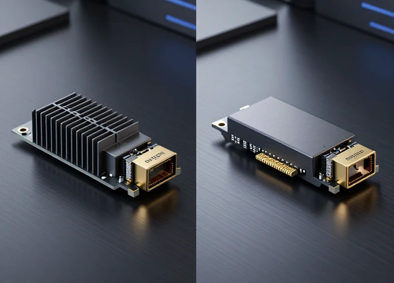
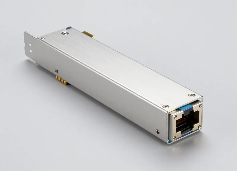
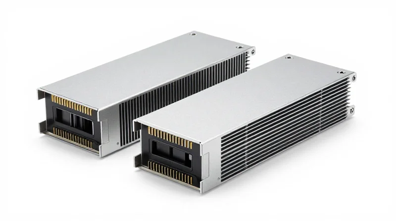
The implementation of 400G LR4 technology is fundamentally dependent on the evolution of pluggable form factors, specifically the QSFP-DD and OSFP standards. These physical interfaces provide the essential bridge between the high-speed electrical signals of the host ASIC and the optical signals transmitted over single-mode fiber. While both form factors utilize an 8-lane electrical interface—each operating at 50Gbps PAM4—they diverge in their mechanical dimensions and thermal handling capabilities, which are critical factors when deploying LR4 optics that must operate reliably over 10km distances.
QSFP-DD: The Industry Standard for Density
The Quad Small Form-factor Pluggable Double Density (QSFP-DD) has emerged as a dominant choice for 400G LR4 due to its exceptional backward compatibility. By adding a second row of electrical contacts, the QSFP-DD maintains the same footprint as legacy QSFP28 modules, allowing data center operators to reuse existing infrastructure. However, the compact size poses significant thermal challenges; 400G LR4 modules often consume between 10W and 12W, requiring the host system to utilize advanced airflow designs or high-efficiency heat sinks to prevent optical degradation over long-distance links.
OSFP: Maximizing Thermal Capacity
In contrast to QSFP-DD, the Octal Small Form-factor Pluggable (OSFP) was designed from the ground up for higher power envelopes. OSFP modules are slightly wider and deeper, but most importantly, they feature an integrated heat sink directly on the module casing. This design allows for superior heat dissipation, often supporting power levels up to 15W or higher. For 400G LR4 applications where internal laser stability is paramount for the 10km reach, the OSFP's thermal headroom can provide a more robust operational margin in high-temperature environments.
| Feature | QSFP-DD | OSFP |
|---|---|---|
| Electrical Lanes | 8 Lanes (PAM4) | 8 Lanes (PAM4) |
| Backward Compatibility | Compatible with QSFP28/QSFP56 | Requires adapter for QSFP |
| Heat Management | External/System Dependent | Integrated Module Heat Sink |
| Max Power Envelope | Approx. 12W - 14W | Up to 15W - 20W |
| Port Density | High (36 ports per 1U) | Moderate (32 ports per 1U) |
Thermal Management and Signal Integrity
For 400G LR4 optics, maintaining a stable temperature is not just about hardware longevity; it is a requirement for wavelength precision. Since the LAN-WDM grid relies on tight 800GHz spacing, thermal fluctuations can cause frequency shifts that lead to crosstalk or signal loss. QSFP-DD modules address this through precise TOSA (Transmitter Optical Sub-Assembly) cooling, whereas OSFP leverages its larger surface area. Both form factors must also manage signal integrity over the PCB traces, utilizing advanced materials and connector designs to minimize EMI and insertion loss at 25-28 Gbaud rates.
- Can I plug a QSFP28 LR4 module into a 400G QSFP-DD port?
Yes, QSFP-DD is designed to be backward compatible with QSFP28. The port will recognize the single row of contacts and operate at 100G speeds accordingly. - Which form factor is better for future 800G upgrades?
OSFP is often viewed as more future-proof for 800G and 1.6T due to its superior thermal dissipation and space for larger optical components, though QSFP-DD800 versions are also in development. - Does 400G LR4 require special cooling in the switch?
While not 'special,' the switch must have adequate CFM airflow and fans capable of handling the 10W+ heat profile of LR4 optics, which is significantly higher than 100G modules.
400G LR4 vs. 400G FR4: When to Choose Which?
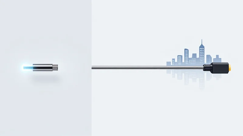
Selecting between 400G LR4 and 400G FR4 is primarily a function of the required optical reach and the resulting tolerance for chromatic dispersion: while FR4 is the standard for high-density data center interconnects up to 2km, LR4 is the essential choice for campus-scale and metro links extending up to 10km.
Wavelength Grids and Dispersion Management
The fundamental technical difference lies in the wavelength grid utilized by each standard. 400G FR4 relies on the Coarse Wavelength Division Multiplexing (CWDM) grid with 20nm channel spacing. This wide spacing is cost-effective but limits the module's ability to combat chromatic dispersion over long distances. Conversely, 400G LR4 utilizes the LAN-WDM grid, which features much tighter 800GHz (approximately 4.5nm) spacing. By clustering wavelengths closer to the zero-dispersion point of standard G.652 single-mode fiber, LR4 maintains signal integrity across the 10km span that FR4 cannot reliably reach.
| Feature | 400G FR4 | 400G LR4 |
|---|---|---|
| Maximum Reach | 2 km | 10 km |
| Wavelength Grid | CWDM (20nm spacing) | LAN-WDM (4.5nm spacing) |
| Laser Type | Uncooled DML/EML | TEC Cooled EML |
| Fiber Type | SMF (Duplex LC) | SMF (Duplex LC) |
| Primary Application | Intra-DC / Leaf-Spine | Campus / Metro / DCI |
Cost and Complexity Considerations
From an operational expenditure perspective, 400G FR4 modules generally offer a lower total cost of ownership for shorter spans. Because the CWDM grid is more forgiving, FR4 transceivers can often utilize uncooled lasers, which reduces power consumption and manufacturing complexity. 400G LR4 modules require sophisticated Thermo-Electric Coolers (TEC) to maintain the precise wavelength stability required by the LAN-WDM grid. This adds to the power draw and the physical cost of the module, making LR4 a premium solution reserved for links where the 2km limit of FR4 is technically insufficient.
Decision FAQ: LR4 vs. FR4
- Can I use 400G LR4 for a 500-meter link?
Yes, LR4 will work perfectly fine for shorter distances, but it is not cost-optimized for that application. You would be paying a premium for cooling and precision that the link does not require. - Are 400G LR4 and FR4 modules interoperable?
No. They use different wavelength grids (LAN-WDM vs. CWDM). If you attempt to connect an LR4 module to an FR4 module, the wavelengths will not align, and the link will not establish. - When should I prioritize LR4 in a greenfield deployment?
Prioritize LR4 for any link that exceeds 2km, or for links approaching 2km where fiber quality is unknown or high patch-panel loss is expected, as LR4 typically offers a more robust optical power budget.
Power Consumption and Sustainability in the Data Center
The Energy Profile of 400G LR4 Optical Modules
Modern 400G LR4 transceivers are engineered to deliver high performance within a strict power envelope, typically consuming between 10W and 12W per module. While this represents an increase in absolute power compared to 100G modules, the 'Watts per Gigabit' metric has improved significantly. By utilizing advanced 7nm Digital Signal Processors (DSP) and high-efficiency Electro-absorption Modulated Lasers (EML), 400G LR4 technology allows data centers to scale their bandwidth by a factor of four without a linear increase in energy consumption or cooling requirements.
Power Comparison Across 400G Formats
Understanding how the LR4 variant fits into the broader 400G ecosystem is essential for capacity planning. The following table illustrates the typical power consumption ranges for various 400G optical interfaces based on their complexity and reach.
| Transceiver Type | Reach | Typical Power Consumption | Primary Use Case |
|---|---|---|---|
| 400G DR4 | 500m | 8W - 10W | Intra-rack / Datacenter |
| 400G FR4 | 2km | 10W | Campus / Inter-switch |
| 400G LR4 | 10km | 10W - 12W | Long Distance / DCI |
| 400G ZR | 80km - 120km | 15W - 20W | Coherent / Metro Link |
Sustainability and Thermal Management in High-Density Ports
In a 1RU switch featuring 32 ports of 400G LR4, the total power draw from optics alone can exceed 380W. This concentration of heat requires sophisticated thermal management to maintain the reliability of the EML lasers, which are sensitive to temperature fluctuations. Data center operators are increasingly adopting liquid cooling or high-airflow chassis designs to mitigate these thermal loads. From a sustainability perspective, the transition to 400G LR4 reduces the physical footprint of the network—requiring fewer switches and cables to move the same amount of data—which ultimately lowers the embodied carbon of the network infrastructure.
Power and Sustainability FAQ
- Does 400G LR4 support low-power modes?
Yes, most QSFP-DD and OSFP implementations support power-saving modes during administrative shutdown, reducing the draw to less than 1W when the port is not active. - How does the DSP impact sustainability?
The DSP is the largest power consumer in the module. Shifting from 16nm to 7nm (and eventually 5nm) DSP architectures is the primary driver for reducing the carbon footprint of 400G optics. - Is LR4 less efficient than FR4?
LR4 typically consumes 1-2W more than FR4 due to the higher power required for the lasers to reach 10km, but it remains highly efficient compared to using multiple 100G links to achieve the same distance.
Key Use Cases: DCI and Metro Networks
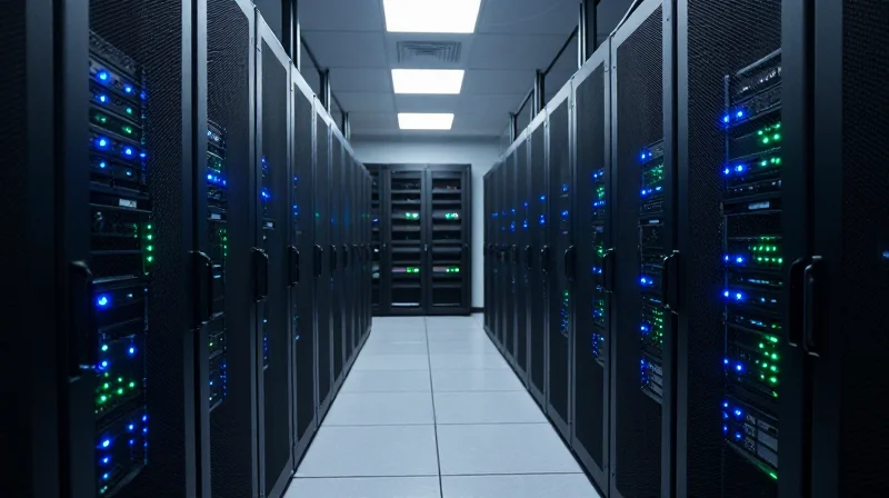
Real-World Deployment Scenarios for 400G LR4
The 400G LR4 transceiver is a critical component for high-bandwidth applications that exceed the 2km limit of standard FR4 optics but do not yet require the extreme distances or significant cost overhead associated with coherent DWDM solutions. By providing a reliable 10km reach over standard single-mode fiber (SMF), LR4 has become the industry standard for bridging the gap between intra-data center connectivity and long-haul metro transport. Its primary value lies in its ability to deliver 400Gbps throughput using existing duplex LC cabling infrastructure, making it a cost-effective choice for metro-scale networking.
Data Center Interconnect (DCI)
In modern cloud computing environments, a single data center often expands into a campus of multiple buildings or distributed facilities within a metropolitan area. 400G LR4 is the preferred solution for connecting these facilities. While 400G DR4 or FR4 optics suffice for internal switch-to-switch links within a single building, the 10km reach of LR4 allows operators to treat geographically separated sites as a single logical resource pool without the latency penalties or complexity of active optical line systems.
5G Mobile Backhaul and Metro Networks
The rollout of 5G technology has dramatically increased the bandwidth requirements of mobile backhaul networks. As base stations transition to higher frequencies and support more connected devices, the link between the Distributed Unit (DU) and Centralized Unit (CU) requires massive capacity. 400G LR4 modules allow telecommunications providers to upgrade their metro rings to 400G, ensuring that the backhaul infrastructure does not become a bottleneck for the high-speed wireless services delivered to consumers.
| Use Case | Reach Requirement | Primary Technical Advantage |
|---|---|---|
| Campus DCI | 2km to 10km | Direct connection over SMF without amplification. |
| 5G Backhaul | 5km to 10km | High-capacity density for metro aggregation points. |
| Enterprise Core | Up to 10km | Future-proofing backbone links using duplex LC fiber. |
Implementation Considerations
- Can I use 400G LR4 for shorter distances like 500 meters?
Yes, but it is often not cost-effective. While technically possible, using LR4 for very short reaches is more expensive than using DR4 or FR4 modules. Additionally, for very short distances, you must ensure the receiver is not saturated, though most LR4 modules have a wide enough dynamic range to handle shorter links without attenuators. - Does 400G LR4 support breakout configurations?
Generally, 400G LR4 is designed as a 4-wavelength multiplexed solution (CWDM4/LWDM4) over a single pair of fibers, meaning it is intended for point-to-point 400G links. If you require 4x100G breakouts, parallel fiber solutions like 400G DR4 or XDR4 are more appropriate. - Is 400G LR4 compatible with older 100G LR4 fiber plants?
Yes, it utilizes the same G.652 single-mode fiber and LC connectors, making it a seamless 'drop-in' upgrade for the physical layer, even though the transceivers themselves use different modulation (PAM4 vs NRZ).
Link Budget and Sensitivity Analysis
Link Budget and Sensitivity Analysis
The 400G LR4 link budget is the precise calculation of allowable optical power loss between the transmitter and receiver, ensuring that signal integrity remains within the thresholds required for successful data recovery over 10km of single-mode fiber. For a standard 400GBASE-LR4 implementation, the link budget typically targets a channel insertion loss of approximately 6.3 dB, which must account for fiber attenuation, connector losses, and the significant dispersion penalties associated with PAM4 signaling at higher baud rates.
Optical Insertion Loss and Dispersion Penalties
Transmission over 10km using the LAN-WDM grid (1295nm to 1310nm) is subject to specific physical constraints. While the 1310nm window minimizes chromatic dispersion, the high symbol rate of 400G (53.125 GBd per lane) makes the signal highly sensitive to even minor chromatic effects. Engineers must account for the Transmitter and Dispersion Eye Closure Quaternary (TDECQ) penalty, which quantifies the reduction in signal-to-noise ratio caused by optical impairments. In the LR4 specification, the maximum TDECQ is often rated around 3.9 dB, meaning the receiver must be significantly more sensitive than in lower-speed legacy modules to maintain the same reach.
| Parameter | Specification (Typical) | Unit |
|---|---|---|
| Maximum Channel Insertion Loss | 6.3 | dB |
| Receiver Sensitivity (OMA, outer) at 2.4e-4 BER external FEC | -9.1 | dBm |
| Transmit Power (per Lane, OMA) | -2.8 to +4.0 | dBm |
| Maximum Dispersion Penalty (TDECQ) | 3.9 | dB |
| Operating Distance | 10 | km |
The Critical Role of KP4 Forward Error Correction (FEC)
Unlike previous generations of 10G or 40G optics that could often operate with an 'error-free' raw bitstream, 400G LR4 relies fundamentally on Forward Error Correction. The IEEE 802.3bs standard mandates the use of KP4 FEC (RS(544, 514)) to achieve an effective Post-FEC Bit Error Rate (BER) of less than 1E-15. The system is designed to operate with a Pre-FEC BER as high as 2.4E-4. This 'FEC gain' effectively expands the link budget by allowing the receiver to accurately reconstruct data even when the optical signal is degraded by noise and dispersion over the 10km span.
Sensitivity Analysis FAQ
- What happens if the link exceeds the 6.3 dB loss limit?
Exceeding the loss budget causes the Pre-FEC BER to rise above the correction threshold of the KP4 algorithm, leading to uncorrectable errors, packet loss, and link instability. - Why is OMA used instead of average power for sensitivity?
Optical Modulation Amplitude (OMA) provides a more accurate measure of the signal's 'swing' in PAM4 modulation, which is more relevant to the receiver's ability to distinguish between the four distinct voltage levels. - Does fiber aging affect LR4 sensitivity analysis?
Yes, network designers typically include a 1-2 dB 'aging margin' in their initial link budget to account for fiber degradation, additional splices, and environmental factors over the lifespan of the installation.
Future-Proofing Your Fiber Infrastructure
Future-Proofing Your Fiber Infrastructure
Future-proofing a 400G LR4 deployment requires a dual focus on physical layer integrity and architectural scalability to ensure that the transition to 800G and 1.6T does not necessitate a complete fiber overhaul. By leveraging high-quality OS2 single-mode fiber and modular switching fabrics, organizations can protect their initial 400G capital expenditure while creating a clear path for future bandwidth expansion.
Pathways to 800G and Beyond
The evolution from 400G to 800G is primarily driven by increases in lane rates, moving from 50G or 100G PAM4 to 200G per wavelength. For those using 400G LR4, the fiber plant is already optimized for 10km reaches, which is a significant advantage. However, as baud rates increase, the sensitivity to Chromatic Dispersion (CD) and Polarization Mode Dispersion (PMD) grows. Ensuring that your current fiber plant is tested beyond the standard 1310nm window—specifically covering the CWDM4 grid—is essential for supporting future multi-wavelength standards.
| Feature | 400G LR4 | 800G LR4 / 2x400G | Evolutionary Impact |
|---|---|---|---|
| Signal Modulation | 50G/100G PAM4 | 100G/200G PAM4 | Requires tighter SNR margins |
| Wavelengths | 4 (CWDM) | 4 or 8 (CWDM/LWDM) | Increased Mux/Demux complexity |
| Power Consumption | 10-12W typical | 16-20W typical | Demands improved thermal management |
| Connector Type | Duplex LC | Duplex LC or MPO-12 | Standardization on LC remains stable |
Infrastructure Longevity Checklist
To ensure 400G LR4 investments remain relevant over the next 5–10 years, network architects should prioritize the following infrastructure standards:
- Fiber Characterization
Conduct full-spectrum testing (1260nm to 1625nm) to identify any water peaks or attenuation irregularities that might hinder future wavelength-division multiplexing. - High-Density Patching
Deploy modular patch panels that support rapid transitions from LC (used by 400G LR4) to MPO/MTP, which may be required for parallel optics at 800G and 1.6T. - Link Budget Padding
Design links with a 1-2 dB margin above the IEEE 802.3bs requirements to account for component aging and additional patches in the future.
Strategic Roadmap FAQs
- Can I use 400G LR4 modules in 800G-ready switches?
Yes, most 800G switches feature QSFP-DD800 or OSFP ports that are backward compatible with 400G QSFP-DD modules, allowing for a phased hardware upgrade. - Will 800G require different single-mode fiber?
No, standard G.652.D OS2 fiber remains the media of choice, but the tolerances for connector cleanliness and splice loss become much stricter at 800G due to reduced link budgets. - Is it better to wait for 800G LR4 instead of deploying 400G LR4 now?
Deployment should be driven by immediate bandwidth needs. 400G LR4 is a mature technology with a stable ecosystem, whereas 800G LR4 is still in early adoption phases with higher initial costs.
In conclusion, 400G LR4 represents the pinnacle of 10km optical transmission, combining LAN-WDM stability with PAM4 efficiency. As your network demands grow, choosing the right optics is essential for maintaining performance and reliability. Ready to optimize your high-speed infrastructure? Contact our technical team today for a comprehensive network assessment and custom component sourcing.