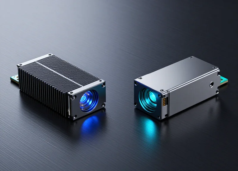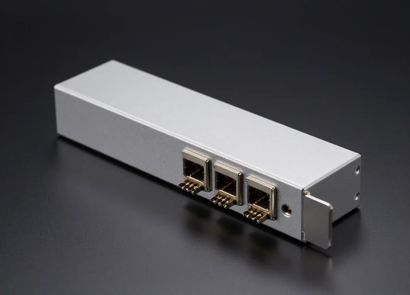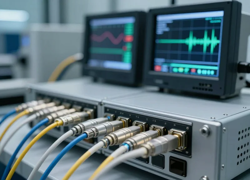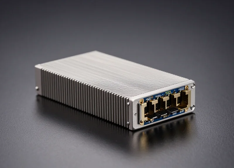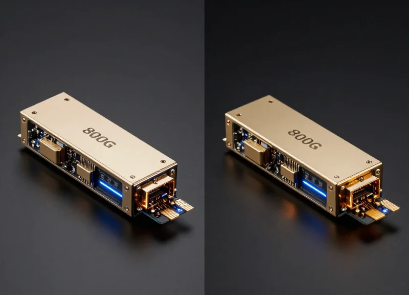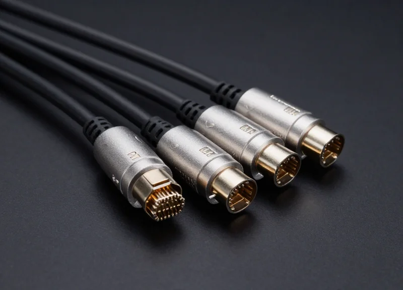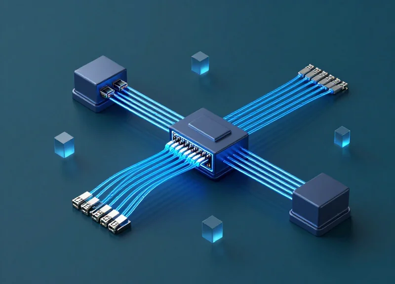
As data centers face an insatiable demand for bandwidth, the transition from 400G to 800G is accelerating. However, the move to 800G isn't always a direct point-to-point upgrade. 2x400G breakout solutions have emerged as a critical architectural strategy, allowing network engineers to utilize high-density 800G ports while maintaining compatibility with 400G infrastructure. This deep dive explores the technical nuances and strategic advantages of this essential networking solution.
The Evolution to 800G: Why Breakout Solutions Matter

The evolution to 800G is driven by the relentless demand for higher throughput in hyperscale data centers, yet breakout solutions remain essential because they bridge the gap between next-generation switch capacities and the existing 400G infrastructure. By utilizing 2x400G breakout configurations, network architects can maximize the radix of high-performance ASICs while providing the flexibility to connect to established 400G endpoints, ensuring a cost-effective and scalable migration path.
The Driving Forces Behind 800G Adoption
As Artificial Intelligence (AI) and Machine Learning (ML) workloads become the standard in modern data centers, the underlying network must evolve to handle massive East-West traffic flows. The move to 800G, powered by 112G SerDes technology, allows for doubling the bandwidth of previous 400G systems within the same physical footprint. However, the ecosystem for 800G network interface cards (NICs) often lags behind switch silicon, making the ability to 'break out' these high-speed ports into usable 400G segments a technical necessity rather than an option.
| Feature | Native 800G Port | 2x400G Breakout Mode |
|---|---|---|
| Primary Use Case | Switch-to-Switch Core Links | Switch-to-Leaf or Leaf-to-Server |
| Hardware Efficiency | Highest possible density | Balanced density and port utilization |
| Infrastructure Compatibility | Requires 800G-capable hardware | Supports existing 400G ecosystems |
| Cabling Complexity | Standard Direct Attach / Fiber | Breakout DACs or MPO-based optics |
Why Breakout Solutions are Mathematically Essential
Modern 800G transceivers, such as the OSFP or QSFP-DD800, utilize eight lanes of 100G (PAM4). A 2x400G breakout solution logically divides these eight lanes into two distinct four-lane groups. This alignment is perfect for interfacing with legacy 400G (QSFP112 or QSFP-DD) modules, which also operate on four lanes of 100G. Without this capability, a switch port would be stranded, operating at only half capacity or requiring an entire hardware refresh across all connected tiers.
Common Questions on 800G Evolution
- Does using a breakout reduce overall system performance?
No. A 2x400G breakout utilizes the full 800G bandwidth of the port; it simply distributes it across two separate physical links to increase connectivity options. - What is the main cost benefit of 2x400G breakouts?
It reduces the cost-per-bit by allowing organizations to use high-density 800G switches while deferring the cost of upgrading every server NIC to 800G simultaneously. - Are there power consumption advantages?
Yes. Consolidating multiple 400G links into fewer 800G switch ports typically results in lower power consumption per gigabit compared to using more 400G switch ports.
Technical Architecture: Decoding the 8x100G Modulation
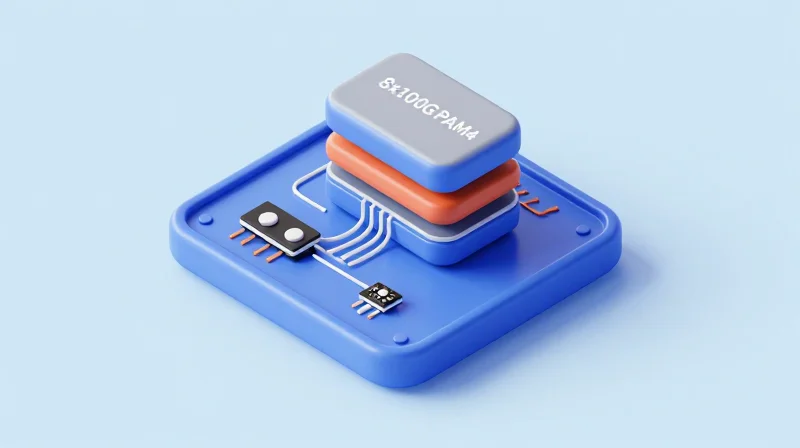
Technical Architecture: Decoding the 8x100G Modulation
The 2x400G breakout architecture is built upon the transition of the physical layer (PHY) to 100G-per-lane signaling, where an 800G transceiver—such as a QSFP-DD800 or OSFP—utilizes eight parallel lanes of 106.25 Gbps PAM4 modulation. By logically and physically partitioning these eight lanes into two distinct groups of four, the hardware can present a single high-density 800G physical port as two independent 400G links. This allows data centers to maintain backwards compatibility with existing 400G infrastructure while effectively doubling the bandwidth capacity per rack unit.
The Role of 112G SerDes and PAM4 Signaling
Pulse Amplitude Modulation 4-level (PAM4) is the cornerstone of this architecture. Unlike traditional NRZ (Non-Return-to-Zero) signaling, which carries a single bit per symbol, PAM4 carries two bits by using four distinct voltage levels. In a 2x400G breakout scenario, the underlying SerDes (Serializer/Deserializer) technology has advanced from 56G PAM4 (used in standard 400G) to 112G PAM4. This doubling of the per-lane data rate allows the same physical connector form factor to handle an aggregate throughput of 800Gbps without increasing the complexity of the cable harness beyond eight pairs.
| Feature | Legacy 400G (QSFP-DD) | 800G Breakout (2x400G) |
|---|---|---|
| Total Electrical Lanes | 8 Lanes | 8 Lanes |
| Per-Lane Data Rate | 53.125 Gbps (56G SerDes) | 106.25 Gbps (112G SerDes) |
| Modulation Type | PAM4 | PAM4 |
| Logical Interface | 1x 400GBASE-DR4/FR4 | 2x 400GBASE-DR4/FR4 |
| Aggregate Throughput | 400 Gbps | 800 Gbps |
Optical Interface and Breakout Connectivity
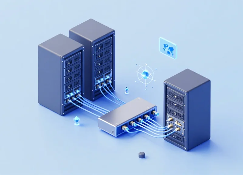
The physical implementation of 2x400G breakouts typically employs 2xDR4 or 2xFR4 optical specifications. For example, an 800G DR8 transceiver features an MPO-16 connector that houses eight pairs of fibers. Through a specialized breakout cable (MPO-16 to 2x MPO-12 or 2x MPO-8), the eight lanes are split into two parallel paths. Each path carries 4x100G lanes, matching the requirements of standard 400G-DR4 optical modules at the receiving end. This configuration is essential for leaf-spine architectures where a single spine switch port must communicate with multiple leaf switches.
Technical FAQs: 2x400G Modulation
- Does 2x400G require specific switch ASIC support?
Yes. The switch Silicon (ASIC) must support 'port channeling' or 'breakout mode' at the MAC/PCS layer to treat the eight electrical lanes as two independent 400G engines rather than one contiguous 800G pipe. - Is 100G PAM4 compatible with older 50G PAM4 hardware?
Direct optical interoperability depends on the gearbox capabilities of the transceiver. While 100G PAM4 is the standard for 800G, many 2x400G modules are specifically designed to bridge the gap to 400G legacy systems using identical signaling rates. - What is the primary power advantage of 2x400G architecture?
By using 112G SerDes, the system reduces the number of physical components and traces required to move data, leading to lower power consumption per bit compared to using multiple discrete 400G line cards.
Form Factors: OSFP vs. QSFP-DD800 in 2x400G Scenarios
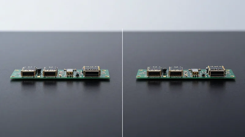
OSFP vs. QSFP-DD800: The Critical Form Factor Choice
Selecting between Octal Small Form-factor Pluggable (OSFP) and Quad Small Form-factor Pluggable Double Density (QSFP-DD800) is the most consequential decision when implementing 2x400G breakout solutions. While both support the 800G throughput required to split into dual 400G links, they offer diverging philosophies regarding thermal dissipation, physical dimensions, and backward compatibility. OSFP is designed for maximum thermal efficiency and future-proofing up to 1.6T, whereas QSFP-DD800 prioritizes seamless integration with existing QSFP ecosystems.
| Feature | OSFP Form Factor | QSFP-DD800 Form Factor |
|---|---|---|
| Max Power Consumption | Up to 30W (Integrated Heatsink) | Up to 25W (Caged/External Heatsink) |
| Backward Compatibility | Requires OSFP-to-QSFP Adapter | Native support for QSFP56/QSFP28 |
| Thermal Management | Superior (Built-in Heatsink) | Moderate (Relies on system-level airflow) |
| Pin Density | 60 pins | 76 pins (Double density arrangement) |
Thermal Management and Power Density
As 2x400G transceivers approach power consumption levels of 20W to 30W, thermal management becomes a bottleneck. The OSFP design incorporates an integrated heatsink directly on the module, which significantly reduces the thermal resistance between the optical engines and the cooling airflow. This allows OSFP to handle higher power envelopes with less reliance on high-velocity system fans. In contrast, the QSFP-DD800 relies on a flat top that interfaces with a heatsink on the switch cage. While this allows for higher port density in 1U chassis, it creates stricter thermal constraints for the 100G PAM4 DSPs used in breakout scenarios.
Backward Compatibility and Ecosystem Integration
The primary advantage of QSFP-DD800 is its native backward compatibility. The 2x400G QSFP-DD800 port can accept legacy 400G QSFP112, 200G QSFP56, or even 100G QSFP28 modules without physical adapters. For data centers with massive existing inventories of QSFP-based hardware, this minimizes operational friction. OSFP requires a physical mechanical adapter to house QSFP modules, which can slightly impact airflow and increase the complexity of the physical layer management during a phased 800G migration.
- Can OSFP and QSFP-DD800 interoperate in a 2x400G breakout?
Yes, as long as the optical specifications (wavelength and modulation) match. For example, an 800G-2xFR4 OSFP module can communicate with two 400G-FR4 QSFP-DD modules, provided the breakout cable or fiber patch panel is correctly mapped. - Which form factor is better for 1.6T upgrades?
OSFP is generally considered better for 1.6T and beyond due to its larger physical size and superior power-handling capabilities, making it the preferred choice for long-term infrastructure planning. - Does QSFP-DD800 suffer from more signal integrity issues?
While QSFP-DD800 has a higher pin density which makes the PCB layout more complex, modern signal integrity engineering and 112G SerDes technology have matured enough to ensure reliable 8x100G performance in both form factors.
Media Options: DAC, AOC, and Structured Cabling
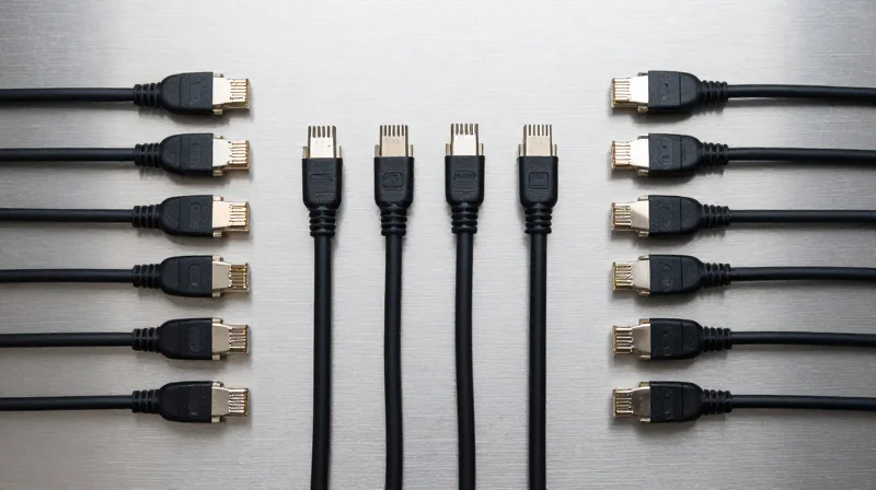
Media Options: DAC, AOC, and Structured Cabling
The choice of interconnect medium for 2x400G breakouts is primarily dictated by the 'reach' required to connect an 800G switch port to two 400G endpoints. In high-density 800G environments, the physical layer must support 112G SerDes signals while managing the thermal challenges inherent in high-wattage modules. Engineers typically choose between Direct Attach Copper (DAC) for intra-rack connections, Active Optical Cables (AOC) for short-span inter-rack links, and structured fiber cabling using discrete transceivers for longer distances.
Direct Attach Copper (DAC): The Efficiency Leader
For very short reaches, typically up to 2 meters, passive DAC cables are the gold standard. Because they lack active optical components, they provide the lowest possible latency and consume zero power, which is vital when 800G switches already push the limits of rack cooling. However, at 112G PAM4 speeds, signal attenuation becomes a significant factor, limiting the length of copper cables compared to previous generations.
Active Optical Cables (AOC): Flexibility and Reach
AOCs utilize multimode fiber with integrated optical transceivers at the ends. They are lighter and thinner than DACs, which significantly improves airflow and cable management in congested racks. Supporting reaches up to 30 meters, 2x400G AOCs are ideal for 'End-of-Row' or 'Middle-of-Row' architectures where the 800G spine/leaf switch needs to breakout to 400G servers or leaf switches in adjacent racks.
Structured Cabling with MPO/MTP Connectors
For enterprise-scale deployments or distances exceeding 30 meters, structured cabling using discrete 800G transceivers (such as 800G-DR8) and MPO/MTP fiber trunks is used. This method offers the highest flexibility, allowing the 800G signal to be split at a patch panel or via a breakout cable (e.g., MPO-16 to two MPO-12 or 8x LC). This approach supports reaches up to 500 meters or even several kilometers depending on the transceiver type (DR8 vs. 2xFR4).
| Media Type | Max Reach | Power Consumption | Latency | Typical Application |
|---|---|---|---|---|
| Passive DAC | ~2.0 Meters | Near Zero | Lowest | Intra-rack (Top-of-Rack) |
| Active Optical (AOC) | Up to 30m | ~14-18W per end | Low | Inter-rack / Row connections |
| Structured Fiber (DR8) | 500m to 2km | ~16-20W per module | Low | Campus/Data Center Interconnect |
Frequently Asked Questions
- Can I use an 800G DAC for a 5-meter breakout?
No. Due to the high insertion loss of 112G PAM4 signaling, passive copper is generally limited to 2-2.5 meters. For 5 meters, an AOC or active copper (ACC) would be required. - What is the primary advantage of AOC over DAC in 800G?
AOCs offer much smaller bend radii and thinner cable diameters, which is critical for maintaining airflow in high-density 800G switch chassis where 32 or 64 ports are fully populated. - Do 2x400G breakouts require special fiber types?
For optical solutions, OM4 or OM5 multimode fiber is used for AOCs, while OS2 single-mode fiber is required for longer-reach DR8 or FR4 breakout transceivers.
Critical Performance Metrics: Latency and Power Consumption
Efficiency Gains: Power Consumption at Scale
2x400G breakout solutions significantly reduce operational expenses by lowering the total power consumption per gigabit of throughput. By utilizing a single 800G port to drive two 400G links, data centers can eliminate redundant hardware components and reduce the physical footprint of the interconnect layer, leading to a more favorable Power Usage Effectiveness (PUE) ratio.
The PUE Advantage of 800G to 2x400G Transitions
Modern 800G transceivers, whether in OSFP or QSFP-DD800 form factors, are engineered with 7nm and 5nm DSPs (Digital Signal Processors). These chips are inherently more energy-efficient than the older generation chips found in legacy 400G modules. When deploying a breakout configuration, the power overhead of the cooling systems is also reduced because one 800G module generates less heat than two independent 400G modules of previous generations. This consolidation is a primary driver for hyperscalers looking to optimize their cooling infrastructure.
| Metric | Dual 400G QSFP-DD | Single 800G (2x400G Breakout) |
|---|---|---|
| Typical Power Draw | ~24W - 30W (Total) | 16W - 24W (Total) |
| Energy Efficiency (W/Gbit) | 0.030 - 0.037 | 0.020 - 0.030 |
| Thermal Management Complexity | High (Multiple Heat Sources) | Moderate (Single Dense Source) |
| Port Density (per 1U) | 32-36 Ports | Up to 72 (via Breakout) |
Signal Integrity and Latency Considerations
Signal integrity in 2x400G breakouts is primarily governed by the 112G PAM4 SerDes performance. While the shift to 112G lanes introduces higher insertion loss challenges, the use of advanced Forward Error Correction (FEC) ensures reliable data transmission. Latency is minimized in breakout scenarios because the internal switching logic within the 800G silicon is optimized for high-speed lane steering, reducing the processing delay that would otherwise occur if data were routed across multiple discrete switch ports and physical layer chips.
- Does FEC increase latency in 2x400G breakouts?
Yes, KP4 FEC adds a marginal latency (typically <100ns), but this is a standard requirement for all 112G PAM4 links and is usually offset by the reduced hop count and simplified fabric architecture of 800G systems. - How do breakout cables affect signal integrity?
Passive DAC breakout cables are limited to shorter distances (under 3m) to maintain signal integrity without active retiming. For longer reaches, AOCs or optical breakouts use DSPs to compensate for signal degradation. - What is the impact on rack-level power density?
2x400G breakouts allow for significantly higher port density in 1U switches. This requires data center managers to plan for higher localized heat per rack unit, even though the total power consumption per gigabit is lower.
Deployment Use Cases: Hyperscale and Cloud Infrastructure

Real-World Application of 2x400G Breakouts
In hyperscale and cloud environments, 2x400G breakout solutions serve as the critical bridge between 800G-capable high-radix switches and existing 400G infrastructure. By splitting a single 800G port into two discrete 400G interfaces, operators can double their effective port density without increasing the physical footprint of the chassis. This capability is fundamental for scaling bandwidth to meet the demands of East-West traffic patterns in modern, flat data center networks.
Optimizing Spine-Leaf Fabric Radix
The primary driver for 2x400G adoption in hyperscale fabrics is the requirement for increased network radix—the number of available ports on a single switch. In a typical Tier-1 cloud architecture, an 800G Spine switch utilizing 2x400G breakout cables can connect to twice as many Leaf switches compared to using standard 400G links. This configuration reduces the number of 'hops' required for data to traverse the fabric, significantly lowering latency and simplifying the control plane management by reducing the total number of physical switches required in the network.
AI Clusters and High-Performance Computing (HPC)
AI and Machine Learning (ML) workloads demand massive, predictable bandwidth with zero packet loss. Deployment of 2x400G solutions at the Top-of-Rack (ToR) level allows for high-density connections to GPU-heavy server nodes. For instance, an 800G OSFP port can be broken out to two 400G QSFP112 ports on separate servers, ensuring that compute resources are never bottlenecked by the network interface while maintaining a streamlined cabling plant.
| Deployment Scenario | Hardware Configuration | Primary Infrastructure Benefit |
|---|---|---|
| Spine-to-Leaf Fabric | 800G Spine port to 2x 400G Leaf ports | Increased radix and reduced network tiers |
| Leaf-to-Server (ToR) | 800G Leaf port to 2x 400G NICs | Ultra-high bandwidth for AI/ML training |
| DCI Breakout | 800G Coherent port to 2x 400G Client ports | Efficient utilization of long-haul optics |
Deployment FAQ
- Can 2x400G breakouts be used across different hardware vendors?
Yes, provided the 800G host port supports port-channeling or breakout modes and the electrical/optical specifications of the breakout media are compatible with the destination 400G ports. - What is the impact on cable management in high-density racks?
While 2x400G reduces switch port consumption, it increases the number of cables. Using structured cabling with MPO-to-LC or MPO-to-SN cassettes is recommended to prevent 'cable spaghetti' in hyperscale environments. - Is special software configuration required for these breakouts?
Most modern Network Operating Systems (NOS), such as SONiC, Junos, or EOS, require specific CLI commands to 'split' an 800G physical interface into two logical 400G interfaces.
Interoperability Challenges and Standards Compliance
Interoperability Challenges and Standards Compliance
Interoperability in 2x400G breakout environments is the fundamental bridge that allows high-density 800G ports to reliably partition into dual 400G links across diverse hardware ecosystems. Achieving this requires a precise alignment of the physical layer (PHY), the management interface, and the forward error correction (FEC) schemes, ensuring that the switch silicon from one vendor can seamlessly interpret the optical signal from a module produced by another. Without strict compliance with Multi-Source Agreements (MSAs), data center operators face significant risks of link flapping, packet loss, or complete hardware incompatibility during leaf-spine scaling.
The Foundations of Standardized Breakouts
The shift to 100G-per-lane electrical signaling necessitates a more robust management framework than previous generations. The Common Management Interface Specification (CMIS) has become the de facto standard for managing 800G and 2x400G modules. CMIS allows the host system to initialize the module, manage power levels, and configure the breakout logic. In a 2x400G scenario, the switch uses CMIS to define the 'Data Path' mapping, effectively telling the hardware to treat eight physical lanes of 100G PAM4 as two independent 400G logical entities.
| Standard/MSA | Focus Area | Impact on 2x400G Breakout |
|---|---|---|
| IEEE 802.3ck | Physical Layer | Defines the 100Gb/s per lane electrical signaling required for reliable transmission across breakout media. |
| CMIS 5.0 and later | Software Interface | Standardizes the register map used by switches to configure port-splitting and diagnostic monitoring. |
| QSFP-DD / OSFP MSA | Mechanical/Thermal | Ensures the physical connector and thermal dissipation are consistent across different transceiver vendors. |
Critical Implementation Obstacles
- Why is FEC mismatch a common issue in breakouts?
Because 2x400G breakouts often bridge different generations of hardware, a mismatch between the host switch's KP4 FEC and the module's internal FEC can lead to uncorrectable bit errors and link instability. - How does Auto-Negotiation affect 2x400G performance?
Auto-negotiation and Link Training (AN/LT) must be synchronized across the breakout cable. If one end of the 2x400G link fails to negotiate the proper lane speed or FEC type, the breakout will fail to come up as two distinct 400G ports. - What is the risk of using non-MSA compliant cables?
Non-compliant cables often lack the correct EEPROM coding required for the host to identify the cable as a breakout assembly, leading to the port being initialized as a single 800G channel instead of dual 400G channels.
Ultimately, the maturation of 2x400G solutions depends on the industry's ability to move beyond proprietary vendor 'locks.' As IEEE 802.3ck continues to stabilize, the reliance on pre-tested interoperability matrices will decrease, allowing for a truly plug-and-play breakout ecosystem in hyperscale environments.
Economic Impact: Capex and Opex Advantages
Leveraging 800G switch ports with 2x400G breakout cables offers a superior economic profile compared to native 400G deployments, primarily by consolidating hardware requirements and reducing the physical footprint of the network. This approach allows data center operators to double their effective port density without expanding their chassis count, leading to a significant reduction in both Capital Expenditure (Capex) and Operational Expenditure (Opex).
Capex Advantages: Hardware Consolidation and Footprint Reduction
The primary Capex advantage lies in the consolidation of switch infrastructure. An 800G-capable switch can support twice the bandwidth of a 400G switch in the same rack unit (RU). By using 2x400G breakouts, operators can connect to existing 400G leaf switches or servers while using half as many spine ports. This reduces the number of expensive switch ASICs and chassis required to support the fabric.
| Economic Metric | Native 400G Deployment | 800G w/ 2x400G Breakout |
|---|---|---|
| Port Density (per RU) | Standard (e.g., 32 ports) | High (e.g., 64 effective ports) |
| Relative Transceiver Cost | Baseline (2x 400G Units) | 15-20% Lower (1x 800G Unit) |
| Cabling Complexity | High (1:1 Ratio) | Medium (Reduced cable volume) |
| Rack Space Utilization | High | Optimized (50% reduction potential) |
Opex Savings: Power, Cooling, and Maintenance
Operational costs are dominated by power consumption and cooling. An 800G QSFP-DD or OSFP module typically consumes less power than the two 400G modules it replaces. This 'power-per-bit' efficiency translates directly into lower electricity costs and a reduced burden on the data center's thermal management systems. Additionally, managing fewer physical modules simplifies inventory and reduces the time required for hardware audits and replacements.
Future-Proofing and Investment Protection
Investing in 800G ports today provides a seamless migration path to future 800G native networking. By using breakouts now, operators protect their investment in high-performance switching silicon, ensuring that the hardware remains relevant as the surrounding server ecosystem eventually transitions from 400G to 800G network interface cards (NICs).
- How does 2x400G breakout impact power-per-bit?
It significantly improves efficiency; a single 800G optical engine is designed with more integrated components than two 400G engines, reducing the total thermal envelope for the same bandwidth. - Is the initial cost of 800G optics higher?
While a single 800G module costs more than a single 400G module, the cost per 400G link is typically 15% to 20% lower when using a breakout configuration due to manufacturing efficiencies at the 800G scale. - Does this solution reduce cabling costs?
Yes, by using breakout cables (DAC or AOC), you reduce the total number of transceiver housings and can simplify the cable management pathways within the rack.
2x400G breakout solutions represent the most flexible and cost-effective path for organizations looking to scale their networks without a complete hardware overhaul. By understanding the technical specifications and choosing the right media, network architects can future-proof their infrastructure today. Ready to optimize your high-speed interconnects? Explore our professional-grade 800G product line or consult with our engineering team for a tailored solution.