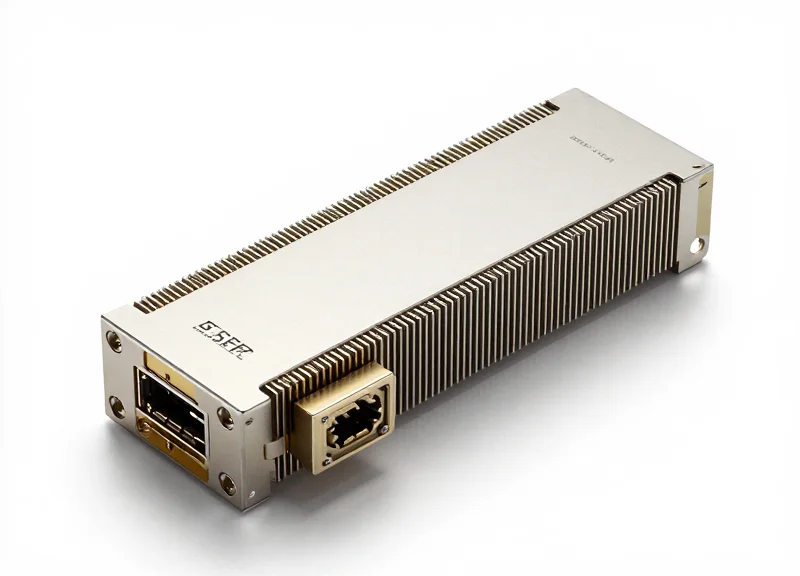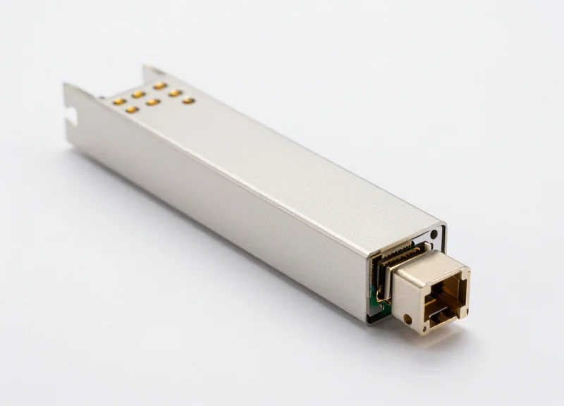
The demand for bandwidth is reaching an inflection point, forcing global enterprises to move beyond 100G standards. This article explores how Ubytelink's migration modules solve the technical hurdles of 400G adoption, ensuring your infrastructure is prepared for the next generation of data processing.
The Strategic Shift: Why 400G is Essential for Modern Infrastructure

The migration from 100G to 400G is no longer a luxury for early adopters; it is a critical response to the exponential surge in global data traffic. As legacy 100G infrastructures reach their physical and economic capacity limits, 400G solutions provide the essential bandwidth, port density, and power efficiency required to sustain the next generation of digital services and enterprise growth.
Market Catalysts: AI, ML, and Hyperscale Demands
The primary engine behind the 400G shift is the rapid adoption of Artificial Intelligence (AI) and Machine Learning (ML). These workloads demand massive data throughput and ultra-low latency to synchronize large-scale compute clusters. Training sophisticated models involves transferring petabytes of data, where 100G interfaces often become the primary bottleneck. By transitioning to 400G, operators ensure that expensive GPU and TPU resources remain fully utilized, optimizing the return on investment for high-performance computing (HPC) environments.
| Feature | 100G Ethernet (Legacy) | 400G Ethernet (Modern) |
|---|---|---|
| Max Throughput | 100 Gbps | 400 Gbps |
| Modulation Technology | NRZ or 50G PAM4 | 50G or 100G PAM4 |
| Typical Form Factor | QSFP28 | QSFP-DD / OSFP |
| Power Consumption | Higher per Gbps | Lower per Gbps |
| Fiber Utilization | High Cable Density | Optimized via Breakouts |
Optimizing Operational Efficiency and TCO
Beyond raw speed, the 400G transition is a play for operational sustainability. Modern 400G transceivers and switches significantly reduce the power-per-bit ratio compared to 100G equivalents. For data center operators, this translates to lower cooling costs and a reduced carbon footprint. Furthermore, 400G allows for greater port density, enabling four times the bandwidth in the same rack space, which is vital for urban data centers where physical real estate is at a premium.
- Why not simply aggregate multiple 100G links?
While Link Aggregation (LAG) is possible, scaling 100G links linearly increases management complexity, cabling bulk, and power overhead. 400G provides a cleaner, more efficient single-pipe solution that reduces the Total Cost of Ownership (TCO). - Is 400G infrastructure backwards compatible?
Yes, through the use of QSFP-DD form factors and breakout cables (e.g., 400G to 4x100G), operators can maintain compatibility with legacy equipment while gradually upgrading the network core. - How does 400G impact cloud service delivery?
It enables cloud providers to support more concurrent users and higher-resolution content streaming with lower latency, directly improving the end-user experience for SaaS and IaaS platforms.
Ubytelink Engineering: The Architecture of Reliable 400G Modules

Engineering Excellence in 400G Optical Transceivers
Ubytelink 400G modules are engineered to bridge the gap between massive bandwidth requirements and operational stability, utilizing state-of-the-art PAM4 modulation and integrated silicon photonics to minimize signal degradation over extended reaches. By prioritizing a 'reliability-first' design philosophy, these modules ensure that high-speed migration does not come at the cost of network downtime or increased latency.
Core Architectural Components and Design Philosophy
The foundation of Ubytelink’s 400G solution lies in its sophisticated internal component selection. Each module utilizes high-performance 7nm Digital Signal Processors (DSPs) which are critical for processing the complex 4-level Pulse Amplitude Modulation (PAM4) signals. This advanced silicon not only reduces power consumption compared to older 16nm nodes but also enhances signal integrity through robust Forward Error Correction (FEC) algorithms.
| Feature | Standard Industry Specs | Ubytelink Engineering Edge |
|---|---|---|
| DSP Technology | Variable 16nm/7nm | Optimized 7nm for Lower Latency & Power |
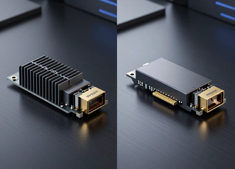
| Thermal Dissipation | Passive Cooling Only | Enhanced Heat-Sink Design & Low-Power Components |
| Signal Modulation | Standard PAM4 | Clean-Eye PAM4 with High Extinction Ratio |
| Optical Engine | Discrete Components | Integrated Silicon Photonics (SiPh) for Stability |
Overcoming the Thermal Barrier
One of the primary challenges in 400G optics is managing the heat generated by high-speed data processing within the compact QSFP-DD or OSFP form factors. Ubytelink addresses this through innovative thermal management. By optimizing the internal PCB layout and utilizing premium thermal interface materials, our modules maintain lower operating temperatures, which directly extends the Mean Time Between Failures (MTBF) and ensures consistent performance in high-density rack environments.
Technical Specifications & FAQ
- Why is 7nm DSP technology important for 400G migration?
7nm DSPs provide superior power efficiency and thermal performance, allowing for higher port density without exceeding the cooling capacity of standard switches and routers. - How does Silicon Photonics improve reliability?
By integrating multiple optical functions onto a single silicon chip, Silicon Photonics reduces the number of discrete components and physical alignments, significantly lowering the risk of mechanical failure. - Are Ubytelink 400G modules backward compatible?
Our QSFP-DD modules are designed to be backward compatible with QSFP28 and QSFP56 ports in most modern switching fabric, facilitating a smoother transition from 100G to 400G.
Solving the Power and Heat Equation in High-Density Ports
Solving the Power and Heat Equation in High-Density Ports
As data centers transition from 100G to 400G, the doubling of port density and quadrupling of bandwidth creates a geometric increase in thermal density; Ubytelink addresses this challenge through ultra-low-power Digital Signal Processors (DSPs) and optimized airflow designs that prevent thermal throttling and significantly reduce long-term operational expenditures.
The Thermal Hurdle: Beyond the 100G Standard
In a 100G environment, a typical QSFP28 module consumes roughly 3.5W to 5W. When moving to 400G using the QSFP-DD form factor, power consumption can climb to 12W or even 15W per module. In a fully loaded 32-port 1U switch, this results in nearly 500W of heat generated solely by the transceivers. Without premium engineering, this heat causes 'hot spots' that degrade optical components, increase bit error rates (BER), and lead to unpredictable network downtime.
| Metric | Standard 100G QSFP28 | Generic 400G QSFP-DD | Ubytelink Optimized 400G |
|---|---|---|---|
| Typical Power Draw | 3.5W - 4.5W | 12.0W - 14.0W | 10.0W - 11.5W |
| Max Operating Temp | 70°C | 70°C | 75°C (Extended range available) |
| DSP Technology | N/A (Analog/Retimer) | 7nm Standard | Optimized 7nm/5nm Low-Power |
| Thermal Dissipation | Standard Fin | Standard Fin | High-Efficiency Integrated Heatsink |
Engineering for Lower OpEx and Sustainability
Ubytelink 100G to 400G Migration Solutions prioritize 'Power-per-Gigabit' efficiency. By utilizing state-of-the-art silicon photonics and advanced 7nm DSPs, Ubytelink modules achieve up to a 20% reduction in power consumption compared to generic alternatives. This reduction is not merely an environmental benefit; it translates directly to lower electricity bills for cooling and power delivery, extending the lifespan of the switch fabric and reducing the Total Cost of Ownership (TCO) over the five-to-seven-year lifecycle of a data center tier.
- How does Ubytelink prevent thermal throttling in high-density switches?
Ubytelink employs custom-milled internal heat spreaders and high-grade thermal interface materials (TIM) that facilitate faster heat transfer from the DSP to the module's outer shell, allowing the switch's fans to exhaust heat more effectively. - Does lower power consumption affect the transmission distance?
No. By improving the Signal-to-Noise Ratio (SNR) within the DSP, Ubytelink maintains full reach specifications (e.g., 500m for DR4 or 2km for FR4) while operating at lower power thresholds than standard modules. - What is the impact of heat on 400G reliability?
Excessive heat accelerates the aging of laser diodes. Ubytelink's thermal management keeps the internal junction temperature within optimal ranges, ensuring the 400G modules maintain a Mean Time Between Failures (MTBF) equivalent to mature 100G products.
Seamless Integration: Ensuring Backward Compatibility with 100G
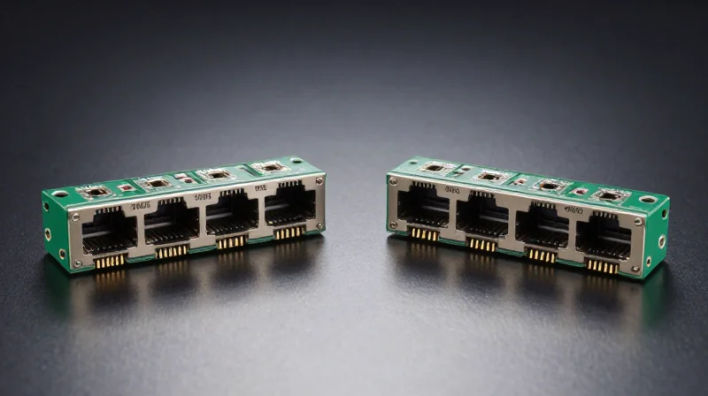
Ubytelink achieves seamless integration by leveraging the dual-density architecture of the QSFP-DD form factor, which allows a single 400G port to support legacy 100G modules without requiring hardware modification. This design philosophy prioritizes investment protection, enabling network operators to scale bandwidth incrementally while utilizing their established 100G assets in a mixed-speed environment.
The Engineering Behind Native Backward Compatibility
The transition from 100G to 400G often presents a 'forklift upgrade' risk, where older hardware becomes obsolete overnight. Ubytelink mitigates this through the implementation of the QSFP-DD (Quad Small Form-factor Pluggable Double Density) standard. By adding a second row of electrical contacts to the interface, Ubytelink modules remain physically compatible with the QSFP28 footprint. This means a 400G switch port can detect and operate a 100G module, effectively allowing for a phased migration where the core is upgraded to 400G while the edge remains at 100G.
| Port Type | Module Type | Compatibility Level | Interoperability Method |
|---|---|---|---|
| 400G QSFP-DD | 100G QSFP28 | Native | Direct Plug-in |
| 400G OSFP | 100G QSFP28 | Via Adapter | OSFP-to-QSFP Adapter |
| 400G QSFP-DD | 4x100G Breakout | Native | DAC/AOC Breakout Cable |
Bridging the Speed Gap: Breakout and Adapter Solutions
For infrastructures utilizing the OSFP form factor—known for its superior thermal performance—Ubytelink provides specialized adapters that allow for the insertion of QSFP28 modules. Furthermore, Ubytelink’s breakout solutions are critical for connecting 400G core switches to 100G leaf switches. By using a 1x400G to 4x100G breakout cable, network administrators can maximize port density on new high-speed switches while maintaining high-fidelity links to existing 100G nodes.
Common Interoperability Questions
- Can a 100G QSFP28 module damage a 400G QSFP-DD port?
No. The QSFP-DD specification is designed to be mechanically and electrically backward compatible. Ubytelink ports are engineered to sense the module type and adjust the power and signal levels accordingly. - How does Ubytelink handle the shift from NRZ to PAM4 modulation?
Ubytelink 400G modules utilize advanced Digital Signal Processors (DSPs) that can translate between the 25G NRZ signals used in 100G modules and the 50G PAM4 signals used in 400G architectures, ensuring error-free data flow across different generations. - Does backward compatibility affect the cooling of the switch?
Ubytelink's 100G modules operate at lower power consumption than 400G modules; therefore, using legacy modules in 400G ports often results in a lower thermal load, which is well within the cooling capacity of 400G-rated chassis.
By eliminating the technical barriers between 100G and 400G protocols, Ubytelink allows global networks to scale at their own pace. This seamless integration ensures that every dollar spent on previous-generation hardware continues to provide value, even as the network core evolves to meet the demands of AI and hyperscale computing.
Latency and Signal Integrity: The PAM4 Advantage
Ubytelink's 400G migration solutions utilize Four-Level Pulse Amplitude Modulation (PAM4) as the cornerstone of high-speed data transmission, doubling the data rate of traditional Non-Return-to-Zero (NRZ) signaling by transmitting two bits per symbol. This technological leap allows Ubytelink modules to achieve the massive throughput required for hyperscale data centers while operating within the physical bandwidth limitations of existing fiber infrastructure and optical components.
PAM4 vs. NRZ: A Technical Comparison
In traditional 100G NRZ signaling, data is transmitted as a series of ones and zeros using two voltage levels. However, pushing NRZ to 400G would require a baud rate so high that signal degradation and electromagnetic interference would become unmanageable. PAM4 solves this by using four distinct signal levels (00, 01, 10, 11), effectively packing more data into the same time interval.
| Feature | NRZ (100G Standard) | PAM4 (400G Standard) |
|---|---|---|
| Signal Levels | 2 (High/Low) | 4 (0, 1, 2, 3) |
| Bits per Symbol | 1 Bit | 2 Bits |
| Nyquist Frequency | 28 GHz for 56 Gbps | 14 GHz for 56 Gbps |
| Signal-to-Noise Ratio | High (Easier to decode) | Lower (Requires FEC) |
Mitigating Signal Loss with Advanced DSP and FEC
Because PAM4 uses four voltage levels instead of two, the 'eye diagram' is much smaller, making the signal more susceptible to noise and jitter. Ubytelink mitigates this through integrated high-performance Digital Signal Processors (DSP) and Forward Error Correction (FEC). Our modules implement KP4 FEC, which identifies and corrects bit errors in real-time. This ensures that even as data density increases, the Bit Error Rate (BER) remains within acceptable limits for mission-critical reliability.
Optimizing Latency for Real-Time Applications
A common concern with PAM4 and FEC is the introduction of latency due to the processing time required for error correction. Ubytelink addresses this by optimizing the DSP algorithms to provide the lowest possible nanosecond-level latency overhead. For high-frequency trading and AI training clusters, where every microsecond counts, Ubytelink provides a balance between raw speed and signal stability.
- Does PAM4 signaling increase the hardware cost?
While PAM4 requires more complex DSP components, Ubytelink's vertical integration and manufacturing scale ensure that the total cost per bit is significantly lower than multi-lane NRZ alternatives. - How does Ubytelink handle signal integrity over long distances?
We use precision-engineered TOSA and ROSA components combined with adaptive equalization in the DSP to compensate for chromatic dispersion and signal attenuation in long-reach 400G links. - Can I use PAM4 modules with legacy NRZ equipment?
Direct interoperability requires a 'gearbox' function, which is built into many Ubytelink 400G QSFP-DD modules to translate between 8x50G PAM4 and 10x10G or 4x25G NRZ electrical signals.
Rigorous Quality Assurance: From Bench Testing to Deployment
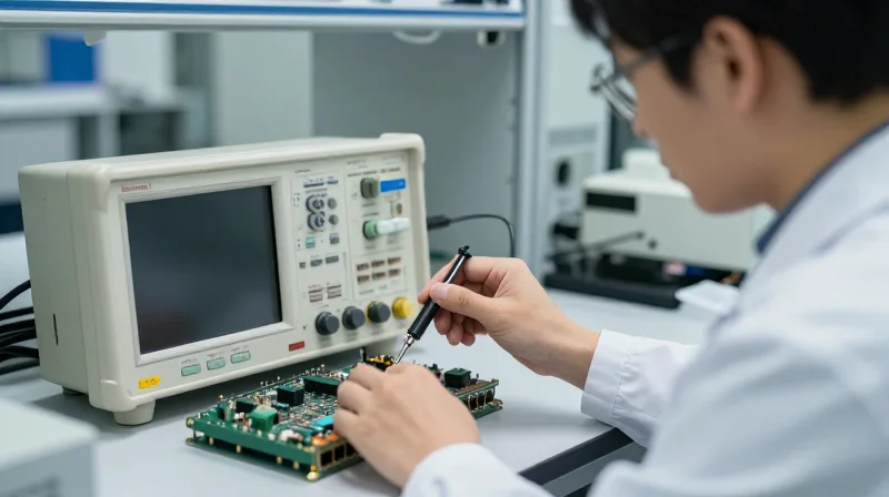
Transitioning from 100G to 400G demands more than just increased bandwidth; it requires a relentless commitment to signal stability and hardware durability. Ubytelink employs a comprehensive testing framework that bridges the gap between theoretical specifications and real-world deployment, ensuring that every optical module delivers zero-packet-loss performance across global network environments. By integrating automated testing at the component level with rigorous system-level validation, we eliminate the risks associated with high-speed data transmission.
The Multi-Stage Validation Ecosystem
Every Ubytelink module undergoes a sequence of evaluations designed to simulate the harshest data center conditions. This starts with Bench Testing, where we analyze the electrical and optical characteristics of the PAM4 signals. We then move to environmental stress screening, where modules are subjected to extreme temperature fluctuations to ensure long-term reliability and thermal stability.
| Test Category | Key Parameters | Performance Objective |
|---|---|---|
| Signal Integrity | Eye Diagram, BER (Bit Error Rate) | Maintain PAM4 linearity and ensure Pre-FEC BER exceeds industry standards. |
| Environmental Stress | Thermal Cycling, High-Temp Soak | Verify mechanical and optical stability between -40°C and +85°C. |
| Interoperability | Switch Compatibility, Protocol Handshake | Seamless operation with Cisco, Arista, Juniper, and other major OEM hardware. |
| Physical Durability | Mating Cycles, Vibration Testing | Ensure the connector interface withstands frequent hardware refreshes. |
Ensuring Global Interoperability and Compliance
Quality assurance at Ubytelink is not just about internal metrics; it is about meeting the stringent demands of global standards. Our modules are fully compliant with IEEE 802.3bs and the Multi-Source Agreement (MSA) specifications. Furthermore, we maintain a vast library of host devices from market-leading vendors to perform live interoperability testing, guaranteeing that our 400G solutions provide a 'plug-and-play' experience in mixed-vendor environments.
Frequently Asked Questions About Quality Control
- Does Ubytelink test every individual module or just batches?
We perform 100% individual testing. Every single module that leaves our facility has been individually validated for optical power, wavelength accuracy, and signal integrity to ensure consistency across large-scale deployments. - How does Ubytelink handle Bit Error Rate (BER) in 400G links?
While 400G relies on Forward Error Correction (FEC), Ubytelink tests the raw Pre-FEC BER to ensure it is significantly better than the threshold, providing a safety margin that prevents link flapping and latency spikes. - Are the modules compatible with legacy 100G equipment?
Yes, our testing protocols include backward compatibility checks to ensure that 400G QSFP-DD modules can interface correctly with 100G QSFP28 ports where supported by the host hardware.
Optimizing Total Cost of Ownership (TCO) during Migration
Optimizing Total Cost of Ownership (TCO) during Migration
Maximizing the lifecycle value of a 400G network depends on prioritizing 'quality-first' procurement to minimize operational expenditures (OpEx), specifically through reduced power consumption, lower failure rates, and extended hardware longevity. While the Capital Expenditure (CapEx) for premium modules like Ubytelink's may appear higher upfront compared to budget-grade alternatives, the total cost of ownership is significantly lower due to the elimination of hidden costs associated with downtime, troubleshooting, and frequent hardware replacements.
The Shift from CapEx to OpEx Strategy
In high-density 400G environments, power and cooling represent the largest share of ongoing costs. Ubytelink’s 400G QSFP-DD and OSFP modules utilize advanced 7nm DSP technology and optimized PAM4 modulation to achieve industry-leading low power consumption per bit. This efficiency reduces the thermal load on data center HVAC systems, directly lowering utility bills and extending the life of the surrounding switch infrastructure.
| TCO Factor | Generic/Budget Modules | Ubytelink Premium Modules |
|---|---|---|
| Annualized Failure Rate (AFR) | 1.5% - 3.0% | <0.1% |
| Power Consumption | 12W - 14W per module | 8.5W - 10W (Optimized) |
| Link Maintenance | High (Troubleshooting required) | Minimal (Plug-and-Play) |
| Interoperability | Limited/Vendor Lock-in | Broad Multi-Vendor Support |
| Warranty & Support | Standard 1-Year | Extended Global Support |
Reliability as a Cost-Saving Driver
Unscheduled downtime is the single greatest threat to TCO. By implementing rigorous bench testing and signal integrity validation, Ubytelink ensures that each module exceeds the Mean Time Between Failures (MTBF) of standard industry components. This reliability reduces the need for on-site technical interventions and expensive emergency RMA logistics, which can often cost five times the price of the module itself. Furthermore, Ubytelink's focus on backwards compatibility ensures that 100G legacy systems can be integrated seamlessly, protecting previous investments while scaling for the future.
- How does 400G migration impact long-term energy costs?
400G migration significantly improves energy efficiency by providing four times the bandwidth of 100G with only a marginal increase in power. Ubytelink modules further optimize this by using low-power silicon designs that reduce the carbon footprint and utility expenses of the data center. - What is the typical ROI period for premium Ubytelink modules?
Most enterprise and service provider networks see a full return on investment (ROI) within 14 to 18 months through the reduction of maintenance labor and the elimination of hardware-related outages. - Does higher quality help in multi-vendor environments?
Yes. Premium quality ensures stricter adherence to IEEE and MSA standards, which eliminates the hidden costs of 'vendor lock-in' and allows network architects to mix and match hardware without facing interoperability-induced signal degradation.
Future-Proofing: Scaling from 400G toward 800G and Terabit Ethernet

Future-proofing a network requires more than just meeting current bandwidth demands; it necessitates a strategic investment in hardware that aligns with the roadmap of IEEE and MSA standards. Ubytelink 100G to 400G Migration Solutions are engineered to bridge the gap between current deployments and the looming 800G era, ensuring that the physical layer remains a robust asset rather than a bottleneck. By adopting 112G SerDes-ready components today, organizations can significantly reduce the complexity and cost of subsequent upgrades to 800G and Terabit speeds.
The Architecture of Next-Generation Scalability
The transition from 400G to 800G is primarily driven by doubling the lane rate from 56G to 112G or increasing the number of lanes via advanced form factors like OSFP and QSFP-DD800. Ubytelink modules utilize high-grade silicon photonics and low-power DSPs that are specifically tested for interoperability with next-gen switching silicons. This forward-thinking design ensures that signal integrity is maintained even as modulation schemes become more complex and power budgets tighten.
| Specification | 400G Current Standard | 800G Emerging Standard | Terabit Ethernet Outlook |
|---|---|---|---|
| Lane Velocity | 56G / 112G PAM4 | 112G / 224G PAM4 | 224G+ / Coherent |
| Form Factors | QSFP-DD / OSFP | OSFP / OSFP1600 | CPO / LPO Integration |
| Power Efficiency | ~10-12W per module | ~16-20W per module | <15W (Target via CPO) |
| Typical Reach | 500m - 10km | 100m - 2km (Initial) | Extended via DWDM |
Strategic Advantages of Ubytelink's Roadmap
As the industry moves toward 800G, the focus shifts toward power density and thermal management. Ubytelink's premium modules are designed with optimized heat dissipation surfaces and high-efficiency TOSA/ROSA components. These features are critical for maintaining the reliability of high-density 800G line cards where thermal throttling can lead to packet loss and hardware degradation. By standardizing on Ubytelink's 400G solutions now, enterprises adopt a deployment methodology that is directly transferable to 800G optics.
Frequently Asked Questions: Scaling Beyond 400G
- Will my current fiber plant support the move to 800G?
Most high-quality SMF (Single Mode Fiber) and MPO-12/MPO-24 cabling installed for 400G will support 800G, provided that the link budget accounts for the higher insertion loss requirements of next-gen transceivers. - Why is 112G SerDes compatibility important for 400G modules?
112G SerDes allows for 400G to be delivered over 4 lanes instead of 8, reducing complexity and power consumption, while providing a direct technological path to 800G which uses 8 lanes of 112G. - How does Ubytelink assist in reducing Total Cost of Ownership (TCO) during this transition?
By providing modules with superior MTBF (Mean Time Between Failure) and future-ready lane configurations, Ubytelink minimizes the need for 'rip-and-replace' upgrades, allowing for incremental scaling.
In conclusion, the migration from 100G to 400G with Ubytelink is not just a bandwidth upgrade—it is a long-term infrastructure strategy. By prioritizing signal integrity, thermal efficiency, and standards compliance, Ubytelink ensures that your network is prepared for the 800G and Terabit transitions of the next decade.
Successful 400G migration requires more than just hardware; it requires a commitment to quality and technical foresight. Ubytelink provides the premium modules necessary to bridge the gap between today's needs and tomorrow's demands. Contact our engineering team today to receive a comprehensive migration roadmap for your global network.