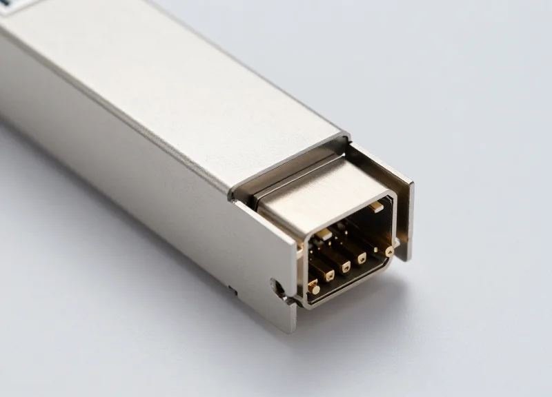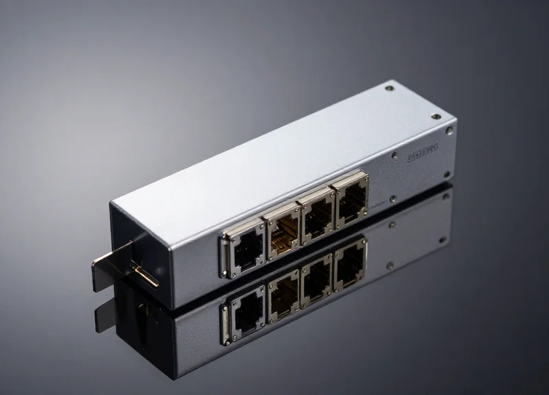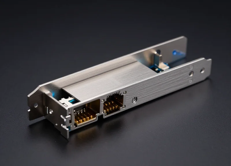
Navigating the complexities of modern networking requires more than just high-quality hardware; it demands seamless interoperability. As data demands surge, 'Cisco Compatibility Mastery' has emerged as a critical discipline for engineers seeking to balance performance with cost-efficiency. This deep dive explores how third-party optics achieve 100% parity with Cisco hardware and why it matters for your bottom line.
The Evolution of Optical Interoperability in Cisco Environments

Cisco Compatibility Mastery is the technical discipline of navigating the shift from historically closed hardware ecosystems to today's standardized multi-vendor environments, where software-defined validation and Multi-Source Agreements (MSAs) dictate system performance.
The Genesis of the Closed-Loop Ecosystem
Initially, Cisco networking hardware operated within a 'walled garden' where signal integrity was maintained through strict proprietary checks. Every transceiver required a specific Cisco-encoded signature within its EEPROM to be recognized by Catalyst or Nexus switches. If the signature was missing, the operating system would immediately place the port into an 'err-disable' state, effectively mandating a single-vendor supply chain for all optical interconnects.
Standardization and the MSA Revolution
As data center demands scaled, the industry-wide adoption of Multi-Source Agreements (MSAs) fundamentally changed the market. These agreements established common physical and electrical specifications for form factors like SFP, QSFP, and QSFP-DD. Cisco's evolution involved moving the compatibility barrier from the physical layer to the software layer, allowing for broader hardware support while maintaining a system of internal warnings and logging for non-Cisco modules.
| Attribute | Legacy Proprietary Model | Modern Interoperability Model |
|---|---|---|
| Verification Method | Hardcoded Vendor IDs | MSA-compliant EEPROM Metadata |
| Error Handling | Port err-disable | Warning logs / Software-enabled ports |
| Cost Profile | High (Premium Vendor Pricing) | Optimized (Multi-source competition) |
| Diagnostic Access | Proprietary DOM | Standardized Digital Monitoring |
The Technical Complexity of Modern Validation
Mastering Cisco compatibility in the current era requires understanding the nuances of IOS-XE and NX-OS. It is not merely about toggling hidden commands; it is about ensuring that third-party optics provide the correct Digital Optical Monitoring (DOM) data to prevent silent errors. Mastery involves the expert application of validation protocols to ensure that high-speed links—from 10G to 800G—meet the strict signal-to-noise ratios required by modern silicon.
- Why did Cisco transition away from strict hardware lock-in?
The emergence of industry-standard MSAs and the demand for rapid scaling in cloud environments made it impossible for any single vendor to sustain a closed ecosystem without limiting their own hardware's utility. - What is the significance of the 'service unsupported-transceiver' command?
It represents the bridge between legacy lock-in and modern flexibility, allowing network engineers to bypass software-based vendor checks while assuming responsibility for link performance.
Decoding the EEPROM: The Secret to 100% Compatibility
At the heart of Cisco compatibility lies the EEPROM (Electrically Erasable Programmable Read-Only Memory), a non-volatile storage chip that serves as the transceiver's digital passport. For a third-party module to achieve 100% compatibility, it must do more than just meet physical and electrical standards; it must present a data map that is indistinguishable from an original Cisco module. This involves meticulous programming of the memory registers to provide the correct Vendor Name, Part Number, and Serial Number, alongside proprietary Cisco-specific codes that satisfy the 'handshake' protocol during the initial hardware insertion.
The Anatomy of the EEPROM Data Map
Optical transceivers follow Multi-Source Agreement (MSA) standards, such as SFF-8472 for SFP+ or SFF-8636 for QSFP+, which define the memory map structure. However, Cisco utilizes specific bytes within these maps to store proprietary validation signatures. If these signatures are missing or calculate an incorrect checksum, the Cisco IOS/NX-OS will flag the module as 'Unknown' or 'Unsupported'.
| EEPROM Field | Typical Byte Address | Role in Cisco Compatibility |
|---|---|---|
| Vendor Name | 20 - 35 | Must be programmed as 'CISCO-SPECIFIC' or a recognized vendor string. |
| Vendor PN | 40 - 55 | Maps the module to a specific Cisco SKU (e.g., SFP-10G-LR). |
| Serial Number | 68 - 83 | A unique identifier used for inventory and tracking within the OS. |
| Cisco Extension | 96 - 127 | Contains proprietary algorithms and checksums required for authentication. |
The Checksum Challenge and Verification
Cisco devices perform a real-time validation check upon module insertion. This process reads the EEPROM content and runs a cyclic redundancy check (CRC) or a proprietary hash function against the data stored in the upper memory pages. Compatibility mastery requires not only the correct strings but also the ability to calculate these unique checksums based on the specific serial number and hardware version of the transceiver.
Common Compatibility Hurdles
- What happens if the checksum is incorrect?
The Cisco switch will typically place the interface into an 'err-disabled' state, preventing any data transmission until the module is replaced or forced with specific commands. - Why does 'service unsupported-transceiver' exist?
This command allows the switch to ignore the validation check for certain third-party modules, but it does not guarantee full DOM (Digital Optical Monitoring) support or performance reliability. - Can an EEPROM be reprogrammed in the field?
While specialized coding boxes exist, professional compatibility mastery ensures the EEPROM is correctly locked and validated during the manufacturing process to prevent corruption.
Ultimately, decoding the EEPROM is about technical integrity. True mastery ensures that every byte—from the basic MSA fields to the complex Cisco-specific extensions—is precisely aligned to provide a 'plug-and-play' experience that mirrors official hardware.
Cisco IOS and the 'Service Unsupported-Transceiver' Command
Cisco IOS and the 'Service Unsupported-Transceiver' Command
The 'service unsupported-transceiver' command is the critical configuration bridge in Cisco IOS that allows network administrators to override the default system behavior of disabling non-Cisco coded hardware. By default, Cisco switches execute a security and validation check on the transceiver's EEPROM; if the vendor ID does not match Cisco’s proprietary signature, the software triggers an 'err-disable' state on the port, effectively shutting down the link to prevent potential instability. Mastery of this command is essential for integrating third-party optics into a Cisco-centric infrastructure, as it manually instructs the IOS to bypass the vendor-check algorithm and attempt to initialize the module.
The Mechanics of the 'Err-Disable' State
When an SFP is inserted into a Cisco switch, the IOS reads the IDPROM (a small memory chip on the transceiver). It specifically looks for a valid Cisco-specific checksum. If this signature is missing or incorrect, the system generates a log message such as `%GBIC_SECURITY_CRYPT-4-ID_OK_BAD_CONF_STR` and immediately places the interface into an error-disabled state. This is not necessarily an indication of a hardware fault, but rather a software policy enforcement mechanism designed to ensure that only tested and validated Cisco-branded components are utilized.
| Feature | Default Cisco Behavior | With 'Unsupported' Command |
|---|---|---|
| Vendor ID Check | Strict validation of Cisco signature | Bypasses signature verification |
| Port Status | Err-Disabled (Link Down) | Enabled (Link Up) |
| Syslog Messages | Critical security/invalid ID error | Informational warning/disclaimer |
| TAC Support | Fully supported | Limited to non-transceiver issues |
Configuring the Override
Applying this configuration is a two-step process. First, the global service command must be entered. Note that in many versions of IOS, this command is hidden and will not appear in the context-sensitive help (the '?' key) or autocomplete via 'Tab'. Second, the port must be reset to clear the existing err-disable state.
Switch(config)# service unsupported-transceiver
Switch(config)# no errdisable detect cause gbic-invalid
Switch(config)# interface TenGigabitEthernet1/1
Switch(config-if)# shutdown
Switch(config-if)# no shutdown
Operational FAQs
- Will this command void my switch warranty?
No. Using third-party optics does not void the hardware warranty of the Cisco switch itself. However, Cisco TAC may require you to replace the third-party module with an official Cisco part if the issue being investigated is related to the optical link. - Does this work on all Cisco platforms?
While standard on Catalyst switches, some Nexus (NX-OS) platforms handle third-party modules differently, often allowing them by default or using 'allow-unsupported-transceiver' commands depending on the firmware version. - Why do some modules still fail after the command?
The command only bypasses the software identification check. If the module has electrical incompatibilities or incorrect DOM (Digital Optical Monitoring) mappings, the port may still fail to initialize properly.
DOM and DDM: Real-Time Diagnostic Mastery

Cisco Compatibility Mastery in diagnostics is the seamless integration of Digital Optical Monitoring (DOM) telemetry into the Cisco IOS environment, enabling network engineers to monitor the physical layer health of a link with the same precision as original equipment manufacturer (OEM) modules. True mastery involves adhering to the SFF-8472 industry standard, which defines the memory map for diagnostic interfaces, ensuring that a compatible transceiver does not just 'work,' but actively reports its operational status to prevent downtime.
The Anatomy of Real-Time Telemetry: DOM vs. DDM
While often used interchangeably, Digital Diagnostic Monitoring (DDM) refers to the broad suite of diagnostic features, whereas Digital Optical Monitoring (DOM) specifically targets the optical performance metrics. For a module to achieve Cisco-grade performance, it must utilize an internal microcontroller that samples analog signals from the laser driver and receiver, converting them into digital values that the Cisco switch can interpret via the I2C serial interface.
| Diagnostic Parameter | Technical Definition | Critical Threshold Impact |
|---|---|---|
| TX Bias Current | The current applied to the laser diode. | High bias indicates laser aging or impending failure. |
| RX Optical Power | The intensity of the incoming light signal. | Low power indicates fiber micro-bends or dirty connectors. |
| Internal Temperature | Real-time heat levels of the module casing. | Overheating leads to wavelength drift and packet loss. |
| Supply Voltage | The DC voltage provided by the host switch. | Fluctuations can indicate power supply unit (PSU) instability. |
Implementing Diagnostic Visibility in Cisco IOS
Achieving diagnostic mastery requires the transceiver to correctly populate the A2h address memory map. When this is executed perfectly, the Cisco IOS command `show interfaces transceiver detail` yields a comprehensive report. This data allows for proactive maintenance, as administrators can set thresholds that trigger SNMP traps before a link actually fails.
Switch# show interfaces Te1/1 transceiver detail
Internal transceiver diagnostics
                              Calibration
Parameter          Value      Standard
-----------------  ---------  ----------
Temperature        32.4 C     Internal
Voltage            3.28 V     Internal
TX Bias Current    5.42 mA    Internal
TX Optical Power   -2.1 dBm   Internal
RX Optical Power   -3.5 dBm   Internal
Diagnostic FAQ: Ensuring Operational Continuity
- Why do some compatible modules show 'N/A' for diagnostics?
This occurs when the module lacks a DDM-capable microcontroller or when the EEPROM programming does not align with Cisco’s expected memory offsets. Mastery requires 100% alignment with SFF-8472. - Can DOM help in troubleshooting intermittent link flaps?
Yes. By monitoring RX power levels over time, engineers can identify if a link flap is caused by physical layer degradation (optical) or logical errors (layer 2/3). - Is DOM support mandatory for all Cisco switches?
Most modern SFP, SFP+, and QSFP slots support DOM, but it must be enabled in the module hardware and recognized by the software to function.
Ultimately, the inclusion of robust DOM/DDM capabilities is what separates professional-grade compatible optics from generic alternatives. By providing a transparent window into the module's physical state, compatibility mastery ensures that the network remains resilient, predictable, and easy to manage.
Signal Integrity and Bit Error Rate (BER) Benchmarks
Signal Integrity and Bit Error Rate (BER) Benchmarks
Cisco Compatibility Mastery is fundamentally a measure of physical layer excellence, where a compatible module must deliver a Bit Error Rate (BER) that meets or exceeds the IEEE 802.3 standard—typically 10^-12 or better. Achieving this level of performance requires precise calibration of the Transmit Optical Sub-Assembly (TOSA) and Receive Optical Sub-Assembly (ROSA) to ensure that signal degradation, such as jitter and dispersion, does not impact the integrity of data frames as they traverse the switch fabric.
Eye Diagram Analysis: The Visual Proof of Quality
In high-speed data transmission, the 'Eye Diagram' is the gold standard for measuring signal health. A mastery-level compatible module exhibits a wide, clear 'eye opening,' indicating low noise and minimal timing jitter. When compared to Cisco originals, these modules maintain significant 'mask margins'—the buffer zone between the signal and the failure threshold defined by industry standards. Lower-tier third-party optics often suffer from 'eye closure,' leading to intermittent packet loss that can be difficult to diagnose via software alone.
| Performance Metric | Cisco OEM Standard | Mastery-Level Compatible | Generic Third-Party |
|---|---|---|---|
| Bit Error Rate (BER) | < 10^-12 | < 10^-12 to 10^-15 | < 10^-10 (Marginal) |
| Eye Mask Margin | > 20% | > 20% | < 5% (Risk of errors) |
| RMS Jitter | < 0.01 UI | < 0.01 UI | > 0.03 UI |
| Optical Sensitivity | -18 dBm to -24 dBm | -18 dBm to -24 dBm | Variable (-15 dBm typical) |
Stress Testing and Thermal Stability
Maintaining signal integrity is not merely about performance at room temperature; it is about consistency across the entire operating range. Mastery-level modules undergo rigorous thermal cycling to ensure that the laser's center wavelength does not drift beyond the specified nanometer range (e.g., 1270nm to 1330nm for 10G-LR). This stability prevents 'link flapping' and ensures that the BER remains constant even as the Cisco chassis reaches peak thermal loads during high-intensity routing tasks.
- How does BER affect network latency?
A high BER triggers Forward Error Correction (FEC) or triggers Ethernet frame retransmissions at the MAC layer. This increases latency and reduces effective throughput, even if the link appears 'Up' in the Cisco IOS. - Why is the Eye Mask Margin important for long-distance links?
A larger margin provides a safety buffer against signal attenuation over long fiber runs. It ensures that even as the signal weakens over distance, the receiver can still distinguish between a logical 0 and 1. - Can a compatible module outperform a Cisco original?
Technically, yes. Some high-end compatible modules utilize superior clock-data recovery (CDR) chips or higher-grade lasers that result in a lower BER (e.g., 10^-15) than the minimum OEM requirement.
Rigorous Testing Protocols for High-Speed Networks
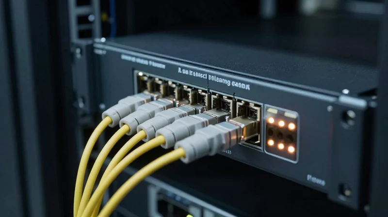
Achieving Cisco Compatibility Mastery necessitates a testing framework that mirrors the extreme conditions of enterprise and data center environments. It is not enough for a module to be recognized by the CLI; it must sustain signal integrity under thermal stress and maintain full feature parity across Cisco’s diverse hardware portfolio. This process involves a transition from bench testing to live environment simulation, ensuring that every transceiver meets or exceeds the original equipment manufacturer (OEM) specifications for latency, power consumption, and error rates.
Platform-Specific Validation: Catalyst vs. Nexus
Cisco’s ecosystem is split between different operating systems and hardware architectures, primarily IOS-XE for the Catalyst series and NX-OS for the Nexus series. Mastery requires validation on both to account for differences in how each system handles the I2C interface and EEPROM data. While a Catalyst 9000 switch may prioritize Power over Ethernet (PoE) budget management and stackability, a Nexus 9000 focuses on ultra-low latency and high-density throughput, requiring distinct testing profiles for each.
| Testing Parameter | Catalyst Series (IOS-XE) | Nexus Series (NX-OS) |
|---|---|---|
| Software Interoperability | Focus on Smart Licensing and DNA Center integration. | Focus on VXLAN, EVPN, and Cloud Scale ASIC compatibility. |
| Power Dynamics | Monitoring thermal dissipation in high-density PoE environments. | Validating low power consumption for massive leaf-spine fabrics. |
| Error Recovery | Testing link-flap protection and port security triggers. | Measuring Buffer-to-Buffer Credit (B2B) and flow control. |
Environmental Stress Testing (EST) and Burn-in
Environmental Stress Testing (EST) is the cornerstone of reliability. This protocol subjects transceivers to 'accelerated aging' through temperature cycling—moving the modules through their rated ranges (typically 0°C to 70°C for commercial grade). During this cycle, the Bit Error Rate (BER) is monitored. A module achieving mastery must maintain a BER of less than 10^-12, ensuring that even under maximum thermal load, the data integrity remains uncompromised.
Key QA Metrics for Network Reliability
- What is the 'Golden Unit' test?
This involves comparing the performance of a compatible module against an original Cisco 'Golden Unit' in a side-by-side loopback test to ensure identical optical reach and sensitivity. - How is long-term stability verified?
Through continuous 24-hour traffic soak tests at 100% load, checking for any frame loss or CRC errors that might indicate an unstable laser or faulty internal chipset. - Why is EEPROM serialization important?
Every module must have a unique serial number that follows Cisco’s algorithm, preventing duplicate ID conflicts in management software like Cisco Prime or DNA Center.
By adhering to these rigorous protocols, third-party transceivers transition from mere 'alternatives' to high-performance components that integrate seamlessly into a Cisco-centric architecture. This level of technical scrutiny ensures that the end-user experiences no difference in uptime or diagnostic capability compared to using OEM-branded optics.
Overcoming the Warranty and Support Myth
The Legal and Policy Realities of Compatible Hardware
Achieving Cisco Compatibility Mastery requires a clear understanding that using third-party transceivers does not legally void a Cisco system warranty or terminate a SMARTnet contract. In the United States, the Magnuson-Moss Warranty Act prohibits manufacturers from conditioning a warranty on the use of any specific brand of component, unless they provide that component for free. Technically, Cisco's own policy states that they will provide support for their products under SMARTnet, though they reserve the right to withhold support specifically for the third-party component itself or if the component is the direct cause of a hardware failure.
Warranty vs. Support: A Technical Distinction
It is critical to distinguish between the 'Product Warranty' (the guarantee that the hardware will function) and 'SMARTnet Support' (the service contract for technical assistance and rapid replacement). While a non-Cisco SFP will not void the warranty of a Nexus chassis, a TAC engineer may ask the administrator to replace the third-party module with an OEM version during troubleshooting to isolate the root cause of a physical layer issue.
| Scenario | Effect on Cisco Warranty | TAC Support Responsibility |
|---|---|---|
| Third-party module installed | None (Legally Protected) | Full support for chassis and IOS-XE/NX-OS. |
| Chassis power supply failure | Fully Covered | RMA provided regardless of transceivers used. |
| Optical link error on 3rd-party SFP | No Coverage | User must contact the module vendor for support. |
| Port damage caused by faulty 3rd-party SFP | May be denied | Support for that specific port may be excluded. |
Frequently Asked Questions Regarding Support
- Will Cisco TAC refuse to open a ticket if I use compatible optics?
No. TAC is obligated to open tickets for system-level issues. They only require the use of OEM optics if the troubleshooting process specifically identifies the third-party module as a potential point of failure. - Does the Magnuson-Moss Act apply to enterprise networking?
Yes. While often cited in consumer automotive cases, the principles of the act prevent 'tie-in sales' provisions that force organizations into exclusive, high-cost OEM ecosystems under the threat of warranty loss. - How do mastery-level vendors handle support differently?
Vendors who have mastered compatibility often provide a lifetime warranty on the module itself, which is frequently superior to Cisco's standard 90-day or 1-year limited hardware warranties.
The most effective strategy for network architects is to maintain a 'Gold Kit' of original Cisco optics. By keeping a small stock of OEM modules on hand, engineers can quickly swap them into a problematic port during a TAC session. This 'Mastery' approach eliminates the vendor-blame game and ensures that the focus remains on resolving the network incident rather than debating component origins.
Scaling to 400G and Beyond: The Future of Compatibility
Cisco Compatibility Mastery reaches its zenith when applied to 400G and 800G architectures, where the margin for error in signal integrity and power consumption is virtually non-existent. Achieving mastery at these speeds means navigating the complex shift from NRZ (Non-Return-to-Zero) to PAM4 (Pulse Amplitude Modulation 4-level) signaling, ensuring that third-party modules can communicate flawlessly with the sophisticated ASICs found in Cisco’s Nexus 9800 and Catalyst 9600 series switches. It is no longer just about the EEPROM signature; it is about meeting the exacting Common Management Interface Specification (CMIS) standards that Cisco platforms use to manage high-density interconnects.
The Evolution of Form Factors: QSFP-DD and OSFP
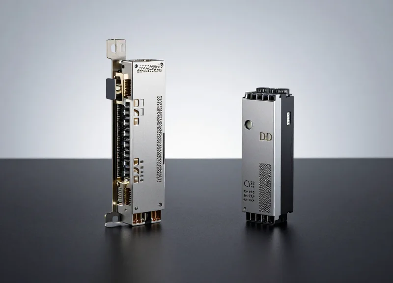
The leap to 400G has introduced two primary form factors that define the future of the data center: QSFP-DD (Quad Small Form Factor Pluggable Double Density) and OSFP (Octal Small Form Factor Pluggable). Cisco Compatibility Mastery involves understanding the distinct physical and thermal profiles of these modules. While QSFP-DD maintains backward compatibility with legacy QSFP28 ports, OSFP offers superior thermal performance designed to scale toward 1.6T speeds. Mastery ensures that regardless of the form factor, the module maintains the thermal envelope required to prevent port throttling on high-density line cards.
| Feature | QSFP-DD (400G) | OSFP (400G/800G) |
|---|---|---|
| Backward Compatibility | High (QSFP+/QSFP28 legacy) | Limited (requires mechanical adapters) |
| Electrical Lanes | 8 Lanes @ 50G (PAM4) | 8 Lanes @ 50G or 100G (PAM4) |
| Thermal Capacity | Up to 12-15 Watts | Up to 15 Watts+ (integrated heatsink) |
| Primary Use Case | High-density Enterprise/Cloud | Next-gen AI and Hyperscale Data Centers |
CMIS Compliance and Software-Defined Optics
In the 400G era, the management interface has evolved from simple I2C registers to the more robust CMIS. This software-defined approach allows Cisco switches to dynamically configure the module's internal Digital Signal Processor (DSP) and manage Forward Error Correction (FEC) settings. True compatibility mastery means the optic can participate in this negotiation, allowing the Nexus Dashboard or DNA Center to provide granular telemetry data, which is essential for predictive maintenance in mission-critical environments.
show interface Ethernet 1/1 transceiver detail
# Look for:
# CMIS Version: 4.0 or higher
# Module State: Ready
# PAM4 Signal Quality: High
Future-Proofing High-Speed Networks FAQ
- Why is PAM4 signaling significant for 400G compatibility?
PAM4 doubles the data rate within the same bandwidth compared to NRZ, but it is significantly more sensitive to noise. Mastery ensures the module's DSP can effectively clean these signals to meet Cisco's Bit Error Rate (BER) requirements. - Does 400G mastery require specific firmware versions?
Yes, Cisco 400G platforms often require modules to support specific CMIS revisions to enable features like auto-negotiation and link training across different cable lengths. - Can I use 400G QSFP-DD modules in older 100G slots?
While QSFP-DD is physically backward compatible, the host port must support the double-density pinout and have the power headroom to support the 400G module's higher consumption.
Cisco Compatibility Mastery is not just about cost savings; it is about building a flexible, high-performance network that remains resilient under pressure. By leveraging the technical insights shared in this guide, you can confidently scale your infrastructure without the constraints of vendor lock-in. Ready to optimize your network? Contact our technical specialists for a compatibility audit today.