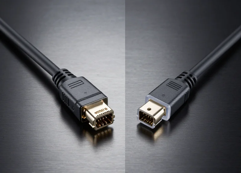
The shift to 400G ethernet represents a massive leap in bandwidth, but it brings significant challenges in thermal management and infrastructure costs. For Silicon Valley tech giants and enterprise data centers alike, the choice between Direct Attach Copper (DAC), Active Optical Cables (AOC), and discrete transceivers is no longer just about distance—it is about optimizing every microjoule of energy and every dollar of CAPEX. In this guide, we dive deep into the technical specifications and economic realities of 400G interconnects.
Understanding the 400G Interconnect Landscape

Understanding the 400G Interconnect Landscape
The 400G interconnect landscape represents a critical evolution in data center architecture, moving beyond traditional 100G limits to support the massive throughput requirements of AI, machine learning, and hyperscale cloud services. At this tier, the choice of interconnect is no longer just about speed, but about balancing port density, thermal management, and power efficiency across diverse physical distances.
The Dominance of QSFP-DD and OSFP Form Factors
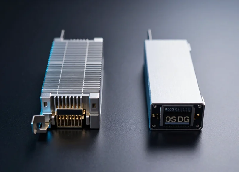
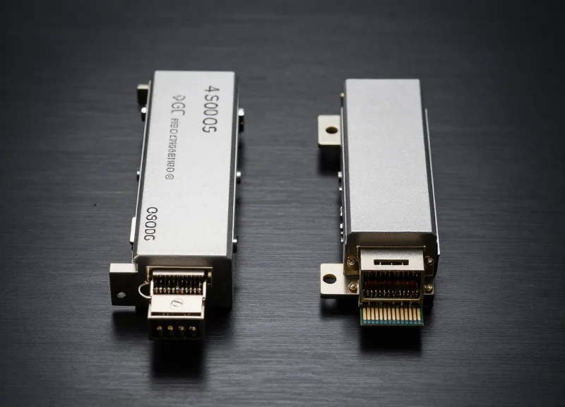
To achieve 400Gbps, the industry utilizes 8 lanes of 50G PAM4 signaling. This requirement has led to the adoption of two primary form factors: QSFP-DD (Quad Small Form Factor Pluggable Double Density) and OSFP (Octal Small Form Factor Pluggable). While both support 400G, they cater to different design priorities regarding backward compatibility and thermal headroom.
| Feature | QSFP-DD | OSFP |
|---|---|---|
| Lanes | 8 Lanes (PAM4) | 8 Lanes (PAM4) |
| Backward Compatibility | High (Supports QSFP+/QSFP28) | Low (Requires Adapter) |
| Thermal Efficiency | Standard (Relies on Host) | Superior (Integrated Heat Sink) |
| Power Capacity | Up to 12W - 14W | Up to 15W - 20W |
Copper vs. Optical: The Distance Divide
Within the 400G ecosystem, the physical medium determines both the cost and the reach. Passive Direct Attach Copper (DAC) cables are the most cost-effective solution for short-range Top-of-Rack (ToR) connections, typically under 2.5 meters. As distances increase, Active Optical Cables (AOC) and discrete optical transceivers take over, using lasers to transmit data over fiber, which overcomes the signal integrity challenges inherent in copper at higher frequencies.
- What is the primary advantage of 400G DACs?
400G DACs provide the lowest possible latency and zero power consumption at the cable level, making them ideal for high-density rack clusters. - Why is OSFP often preferred for future 800G paths?
OSFP’s larger physical size and superior heat dissipation allow it to support the higher power requirements expected in 800G and 1.6T transitions. - When should I switch from DAC to AOC?
Switch to AOC when the required distance exceeds 3 meters or when cable weight and airflow within the rack become a concern.
Latency Benchmarks: The Copper Advantage
Latency Benchmarks: The Copper Advantage
In the context of 400G high-speed networking, latency is primarily a function of signal processing complexity. Passive Direct Attach Copper (DAC) cables represent the absolute floor for latency performance because they function as a direct physical extension of the host switch's electrical bus. By maintaining the signal in its native electrical state from source to destination, DACs eliminate the nanosecond-scale delays introduced by optical modulation and signal regeneration circuitry found in active alternatives.
The Elimination of O-E-O Conversion
Active Optical Cables (AOCs) and transceiver-based solutions must perform Optical-to-Electrical-to-Optical (O-E-O) conversion. This involves a laser driver converting electrical PAM4 signals into pulses of light and a photodiode converting them back at the receiver. Each phase of this conversion adds a specific time penalty. For 400G links, which often require Digital Signal Processing (DSP) within the module to manage signal integrity, these delays are compounded. Passive DACs, being purely metallic, bypass both the O-E-O conversion and the need for integrated DSPs, resulting in near-zero latency relative to the cable medium itself.
| Interconnect Type | Signal Processing Mode | Typical Latency Delay |
|---|---|---|
| 400G Passive DAC | Passive Electrical (No Conversion) | < 0.1 ns |
| 400G AOC | Fixed O-E-O Conversion | 1 - 5 ns |
| 400G Optical Transceiver | DSP-Enhanced O-E-O Conversion | 10 - 100+ ns |
Performance Implications for AI and HFT
The nanosecond advantages of DACs are critical in High-Frequency Trading (HFT) and large-scale AI/ML clusters. In AI training workloads, where thousands of GPUs must synchronize gradients, even minor latency in the interconnect can lead to 'straggler' effects that degrade total compute efficiency. By using DAC cables for Top-of-Rack (ToR) connections, engineers ensure that the physical layer contributes the minimum possible delay to the overall network fabric, optimizing the performance of latency-sensitive RDMA and RoCE protocols.
- Does 400G FEC impact the latency advantage of DACs?
Forward Error Correction (FEC) is required for most 400G links and adds latency at the switch ASIC level. However, because DACs do not add additional O-E-O or module-level DSP latency on top of FEC, they remain the lowest-latency option available. - Are Active Copper Cables (ACCs) as fast as passive DACs?
ACCs include redrivers or linear equalizers to boost signals for longer reach, which adds a negligible amount of latency (measured in picoseconds). They are slightly slower than passive DACs but still significantly faster than any optical solution.
Power Consumption and Thermal Efficiency

Power Consumption and Thermal Efficiency
400G Direct Attach Copper (DAC) cables are the gold standard for energy efficiency in the data center, offering near-zero power consumption and minimal heat generation that significantly reduces both operational expenses and cooling requirements. Unlike active alternatives, passive DACs do not require internal components like lasers or Digital Signal Processors (DSPs), making them the most sustainable choice for short-reach interconnects.
The Zero-Power Advantage of Passive Copper
In a 400G ecosystem, every watt counts toward the total cost of ownership (TCO). Passive DAC cables function as simple point-to-point physical conductors. Because they do not perform Optical-to-Electrical (O-E-O) conversion, their power draw is virtually non-existent, typically measured at less than 0.1 watts per port. This stands in stark contrast to optical transceivers and Active Optical Cables (AOCs), which require active circuitry to drive light signals over fiber.
| Interconnect Type | Power Draw (Per Port) | Thermal Output | Active Components |
|---|---|---|---|
| 400G Passive DAC | < 0.1W | Negligible | None |
| 400G AOC (Active Optical) | 6W - 10W | Moderate | Lasers, ICs |
| 400G SR8/DR4 Transceiver | 10W - 12W | High | DSPs, Lasers, Drivers |
Impact on Thermal Management and Data Center OPEX
The thermal efficiency of DACs provides a secondary economic benefit: reduced cooling costs. High-density racks populated with 400G transceivers can generate significant heat, requiring fans to run at higher RPMs and demanding more from the facility's CRAC (Computer Room Air Conditioning) units. By utilizing DACs for top-of-rack (ToR) switching, network architects can maintain a lower thermal envelope, extending the lifespan of the equipment and improving the Power Usage Effectiveness (PUE) of the entire facility.
- Why do 400G transceivers consume so much more power than DACs?
Transceivers require sophisticated Digital Signal Processors (DSPs) to manage signal integrity and high-power lasers to transmit data over fiber optics, whereas passive DACs rely on the physical properties of copper. - How does power consumption affect port density?
Higher power draw leads to higher heat; if a switch's thermal limit is exceeded, it may require 'stranding' ports (leaving them empty) to prevent overheating. DACs allow for maximum port density without thermal throttling. - Is there a power difference between QSFP-DD and OSFP DACs?
Generally, no. For passive copper DACs, the power consumption remains near zero regardless of the form factor, as the efficiency is derived from the lack of active electronics.
Signal Integrity and the Rise of PAM4 Modulation
The Transition from NRZ to PAM4 in 400G Architecture
The evolution to 400G Ethernet necessitated a departure from traditional Non-Return-to-Zero (NRZ) signaling, which uses two voltage levels to represent a single bit. Because increasing the baud rate of NRZ to reach 400G would result in unsustainable signal loss and electromagnetic interference, the industry adopted Pulse Amplitude Modulation 4-level (PAM4). By utilizing four distinct voltage levels, PAM4 transmits two bits per symbol, effectively doubling the data throughput without requiring a corresponding doubling of the physical bandwidth. However, this increased density comes at a cost: the 'eye' opening in the signal is significantly smaller, making the transmission far more sensitive to noise and jitter.
Signal Integrity Hurdles: Copper vs. Fiber
Maintaining signal integrity with PAM4 is a radically different challenge for Direct Attach Copper (DAC) compared to optical alternatives. In 400G DACs, high-frequency attenuation and skin effect losses occur much earlier in the transmission path. As signal frequency increases, the copper medium's reach diminishes, often limiting passive DACs to 2.5 or 3 meters at 112G-per-lane speeds. Optical fibers, while immune to the electromagnetic interference that plagues copper, face their own hurdles with PAM4, primarily involving the linearity of the laser drivers and the Signal-to-Noise Ratio (SNR) degradation during the Optical-to-Electrical conversion process.
| Feature | NRZ (100G) | PAM4 (400G) |
|---|---|---|
| Voltage Levels | 2 (High/Low) | 4 (00, 01, 10, 11) |
| Bits per Symbol | 1 Bit | 2 Bits |
| Signal-to-Noise Ratio | Higher (Better) | Lower (-9.5dB penalty) |
| Bandwidth Efficiency | 1x | 2x |
| Main Challenge | Clock Jitter | Inter-symbol Interference |
The Role of FEC and Equalization
Because the SNR of a PAM4 signal is roughly 9.5 dB lower than that of an NRZ signal, 400G systems cannot operate 'error-free' without assistance. Forward Error Correction (FEC) is mandatory in 400G architectures to detect and correct bit errors in real-time. While FEC adds a slight amount of latency, it is essential for both DAC and optical solutions to maintain a reliable bit error rate (BER). Additionally, advanced Decision Feedback Equalization (DFE) and Feed Forward Equalization (FFE) are employed within the SERDES to clean up the signal at the receiver end, a process that is significantly more power-intensive for 400G transceivers than for the passive circuitry found in DAC-based environments.
PAM4 Implementation FAQs
- Why does PAM4 limit the distance of 400G DACs?
The reduced SNR and higher insertion loss at 56GHz/112GHz frequencies make it difficult for copper to carry a readable PAM4 signal beyond 3 meters without active amplification. - Does PAM4 affect the latency of 400G cables?
Yes, indirectly. Because PAM4 requires FEC for error correction, the processing time of the FEC algorithm adds approximately 100-150 nanoseconds of latency to the total link. - Can 400G DACs work without FEC?
No. The 400G standard (IEEE 802.3bs/cd) mandates FEC for PAM4 signaling because the raw bit error rate of the four-level signal is too high for standard network operations.
Total Cost of Ownership (TCO) Comparison
Total Cost of Ownership (TCO) Comparison
Calculating the Total Cost of Ownership (TCO) for 400G connectivity requires a dual-lens approach: immediate capital expenditure (CAPEX) and ongoing operational expenditure (OPEX). While 400G Direct Attach Copper (DAC) cables are substantially cheaper to purchase, their true value lies in their passive nature, which contributes zero to the monthly utility bill and places no additional load on data center cooling systems. In contrast, Active Optical Cables (AOCs) and discrete transceiver modules involve active components that consume between 10W and 14W per port, leading to a compounding cost structure over a standard three-to-five-year equipment lifecycle.
CAPEX: Procurement and Hardware Costs
From a procurement standpoint, the bill of materials for a 400G DAC is significantly lower than its optical counterparts. A DAC consists primarily of copper twinaxial cable and mechanical connectors, lacking the expensive Vertical-Cavity Surface-Emitting Lasers (VCSELs), photodetectors, and Digital Signal Processors (DSPs) found in 400G AOCs or transceivers. Typically, a 400G DAC can be acquired at a fraction of the cost of an AOC of the same speed, making it the most economical choice for short-reach top-of-rack (ToR) switching configurations where distances are under 7 meters.
OPEX: Power Consumption and Thermal Management
| Metric | 400G DAC (Passive) | 400G AOC | 400G Transceiver (SR8/DR4) |
|---|---|---|---|
| Power Draw per Port | 0 Watts | 10W - 12W | 12W - 14W |
| Heat Dissipation | Negligible | High | Very High |
| Cooling Requirement | Ambient Airflow | Active Cooling/Fans | Active Cooling/Fans |
| Relative 5-Year OPEX | Lowest | Moderate | Highest |
The operational savings of DACs are often undervalued in initial planning. For every watt of power consumed by an optical module, an additional 0.5 to 1.0 watt of power is typically required for the facility's CRAC (Computer Room Air Conditioning) units to dissipate that heat. In a high-density rack with 32 ports of 400G, using AOCs could add nearly 400W of heat load per switch. Over a year, this results in thousands of kilowatt-hours in electricity and cooling costs that are entirely avoided with passive copper cabling.
TCO and Financial FAQ
- Does the reliability of DACs impact long-term TCO?
Yes. Because DACs have no active electronics or lasers to fail, their Mean Time Between Failure (MTBF) is significantly higher. This reduces the hidden costs associated with maintenance, troubleshooting, and replacement hardware. - Is the TCO of AOCs ever lower than DACs?
Only in specific high-density environments where bulky copper cables might block airflow to the point of causing switch overheating. In such cases, the thinner AOC fiber might improve overall thermal efficiency for the chassis, though this is rare at distances under 5 meters. - How does distance affect the TCO equation?
Beyond 7 meters, DAC is no longer viable due to signal degradation. At that point, AOCs or transceivers become the only options, and TCO shifts toward optimizing fiber infrastructure (e.g., using MPO-12 vs LC connectors) rather than copper-to-fiber comparisons.
Deployment Scenarios: ToR vs. MoR Architectures
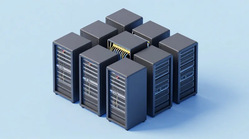
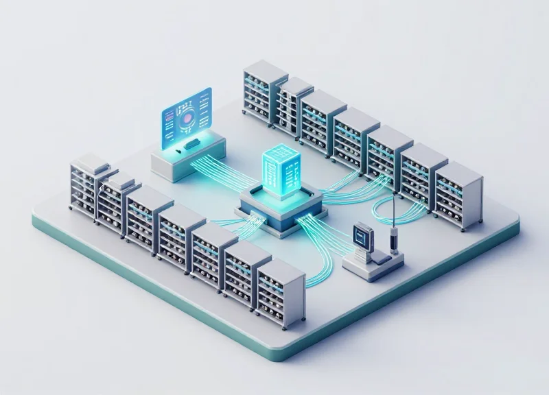
Strategic deployment of 400G connectivity relies on a distance-first methodology where passive DACs are prioritized for the 3-meter radius of a single rack (ToR) to minimize power and cost, while AOCs and structured cabling are reserved for the extended spans of Middle-of-Row (MoR) and End-of-Row (EoR) designs.
Optimizing ToR Architectures with 400G DACs
In a Top-of-Rack (ToR) configuration, the switch is located within the same cabinet as the servers it serves. Because the physical distance for these connections is typically under 2.5 meters, 400G passive DACs offer the highest return on investment. They bypass the power-hungry DSPs and laser components required for optical transmission, resulting in near-zero power consumption and the lowest latency profile available. This makes DACs the de facto standard for high-frequency trading environments and dense GPU clusters where every microsecond and watt counts at the rack level.
Extending Reach: MoR and EoR Deployment Logic
When moving to Middle-of-Row (MoR) or End-of-Row (EoR) architectures, the focus shifts from component cost to cable manageability and reach. MoR designs centralize switches in the middle of a row of racks, often requiring cable runs of 5 to 15 meters. At 400G speeds, copper is physically unable to support these distances without excessive thickness and signal loss. AOCs solve this by using optical fibers to carry the signal while maintaining a fixed-cable form factor, offering the flexibility needed for inter-rack patching without the complexity of discrete transceivers. For spans exceeding 30 meters in EoR setups, discrete transceivers and MPO fiber cabling become mandatory.
| Architecture | Typical Span | Preferred 400G Media | Key Benefit |
|---|---|---|---|
| Top-of-Rack (ToR) | 0.5m - 3m | Passive DAC | Lowest TCO & Power |
| Middle-of-Row (MoR) | 3m - 30m | AOC | Weight & Airflow Optimization |
| End-of-Row (EoR) | 30m - 100m | Transceivers + Fiber | Maximum Reach & Scalability |
Architecture Selection FAQ
- Can I use 400G DACs for MoR if the racks are adjacent?
While physically possible if the distance is under 3 meters, it is generally discouraged for inter-rack MoR use due to the weight and bulkiness of 400G copper cables, which can obstruct airflow and complicate cable management across rack boundaries. - When should I switch from AOCs to discrete transceivers?
Shift to discrete transceivers and MPO/LC fiber when distances exceed 30 meters or when you require the ability to reuse existing structured fiber cabling to simplify hardware upgrades.
Reliability and MTBF Metrics
The Reliability Advantage: Passive Copper vs. Active Optics
When evaluating 400G interconnects, reliability is primarily quantified by Mean Time Between Failures (MTBF), where passive Direct Attach Copper (DAC) cables hold a decisive lead over Active Optical Cables (AOCs) and transceivers. Because a 400G DAC is a passive component—consisting of copper conductors and physical shielding without internal lasers or electronic signal processing—it lacks the complex failure points inherent in optical technology. This simplicity translates to an MTBF that is often an order of magnitude higher than active alternatives, making DACs the gold standard for stability in short-range Top-of-Rack (ToR) deployments.
| Component Type | Complexity | Typical MTBF (Hours) | Common Failure Points |
|---|---|---|---|
| 400G DAC | Passive | 50,000,000+ | Mechanical stress, connector oxidation |
| 400G AOC | Active | 2,000,000 - 5,000,000 | VCSEL laser failure, DSP overheating |
| 400G Transceiver (SR4/DR4) | Active | 1,500,000 - 4,000,000 | Optical misalignment, laser degradation |
Thermal Stress and Component Longevity
The primary drivers of lower MTBF in 400G active components are heat and electronic complexity. 400G AOCs and transceivers utilize Vertical-Cavity Surface-Emitting Lasers (VCSELs) or Silicon Photonics engines combined with Digital Signal Processors (DSPs) to manage high-speed signaling. These components are highly sensitive to the thermal environment within the chassis. As temperatures rise, the probability of laser 'drift' or semiconductor failure increases. In contrast, 400G DAC cables generate zero heat and are virtually immune to the thermal fluctuations that degrade the lifespan of active optical modules, ensuring consistent performance over the entire lifecycle of the networking hardware.
Reliability Metrics FAQ
- How does MTBF impact long-term operational costs?
A higher MTBF reduces the frequency of 'truck rolls' and technician interventions for cable replacements. Since DACs rarely fail, they minimize downtime and the labor costs associated with troubleshooting intermittent link drops often seen in aging optical components. - Why are 400G DACs considered more robust in harsh environments?
Passive copper is less susceptible to environmental stressors like humidity or dust, which can contaminate optical interfaces. Furthermore, DACs do not suffer from the 'burn-in' issues or laser degradation that can occur in active optics over 5-7 years of continuous operation. - Can active electronics in AOCs cause 'silent' failures?
Yes. Active components can experience gradual signal-to-noise ratio (SNR) degradation due to chip aging. This can lead to increased Bit Error Rates (BER) before a total link failure is detected, whereas DAC performance is typically binary: it either works at full specification or has a clear physical fault.
Physical Constraints: Cable Management and Airflow
Physical Constraints: Cable Management and Airflow
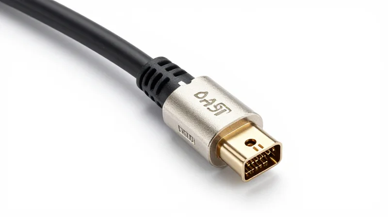
The primary physical drawback of 400G Direct Attach Copper (DAC) cables is their substantial bulk and weight, which creates significant congestion in high-density racks compared to Active Optical Cables (AOCs) or Active Electrical Cables (AECs). While DACs provide unmatched cost efficiency for short-reach connections, their thick copper cores and heavy shielding can obstruct exhaust paths at the rear of switches, leading to higher internal temperatures and increased cooling costs. Consequently, data center managers must balance the financial benefits of DACs against the potential thermal risks and the physical labor required to manage massive cable bundles.
The Gauge Dilemma: Thickness and Bend Radius
To achieve 400G speeds over passive copper, manufacturers often use thicker 26AWG to 30AWG conductors. This increases the cable's outer diameter significantly, making it less flexible and harder to route through tight cable managers. A standard rack filled with 400G DACs can quickly become 'choked' if the cabling is not meticulously planned, potentially exceeding the weight capacity of overhead trays.
| Cable Type | Typical Diameter (mm) | Weight (approx. kg/m) | Flexibility/Bend Radius |
|---|---|---|---|
| 400G DAC (Passive) | 8.5mm - 11.0mm | 0.15 - 0.25 kg | Low (Rigid) |
| 400G AEC (Active Electrical) | 5.0mm - 7.0mm | 0.08 - 0.12 kg | Moderate |
| 400G AOC (Active Optical) | 3.0mm - 4.5mm | 0.04 - 0.06 kg | High (Flexible) |
Thermal Impact and Cooling Efficiency
Airflow obstruction is a hidden cost of thick copper cabling. When cables block the hot-aisle containment or the switch's exhaust fans, the equipment must spin fans at higher RPMs to maintain safe operating temperatures. This creates a recursive loop: more power is consumed by the cooling system, and the noise levels in the data center rise. Transitioning to thinner AOCs or AECs in Top-of-Rack (ToR) scenarios is often done not for distance, but purely to restore proper airflow and reduce the Power Usage Effectiveness (PUE) ratio.
- Does 400G DAC weight affect rack integrity?
In full-scale deployments, the cumulative weight of 400G DACs can reach hundreds of pounds per rack, potentially stressing vertical cable managers and needing reinforced mounting solutions. - How does bend radius affect 400G performance?
Overtightening or sharply bending a 400G DAC can damage the internal shielding, leading to signal degradation and increased bit error rates (BER). - Are AEC cables a viable middle ground?
Yes, Active Electrical Cables (AECs) use thinner gauge wire and signal re-timing chips, offering a significant reduction in bulk compared to passive DACs while remaining more affordable than optical solutions.
Navigating the complexities of 400G infrastructure requires a balanced approach to performance, power, and price. While DAC cables offer unmatched latency and cost benefits for short-reach applications, a hybrid strategy is often the key to a scalable data center. Ready to optimize your network? Contact our technical consulting team today for a personalized interconnect assessment and bulk pricing options.