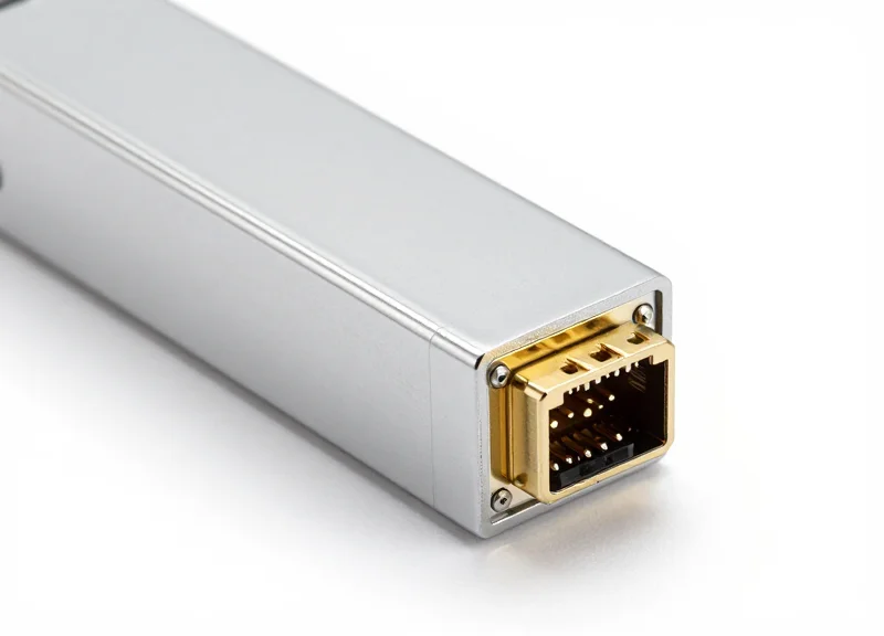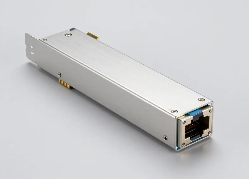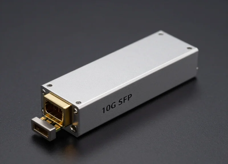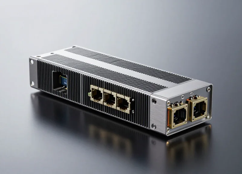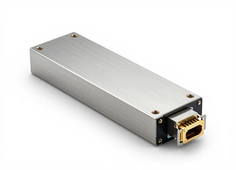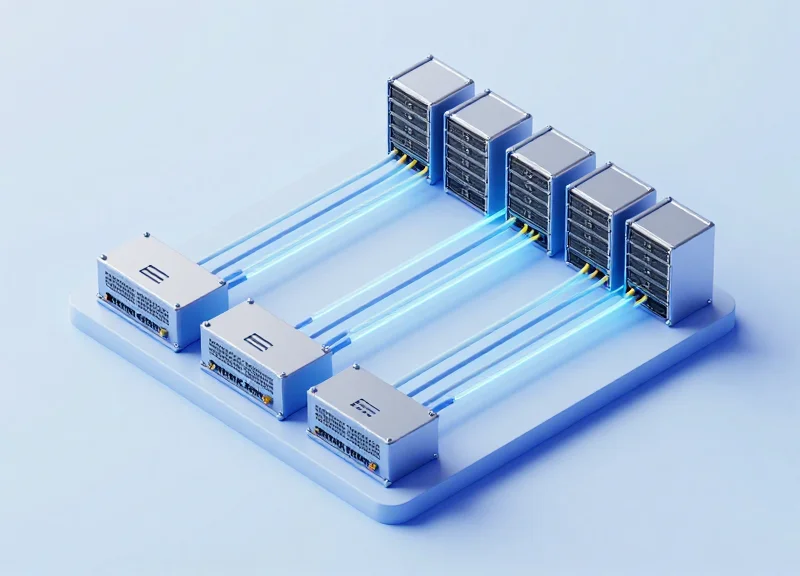
As hyperscale cloud providers push the boundaries of data throughput, 400G Ethernet has transitioned from a future roadmap item to a present-day necessity. At the heart of this short-reach revolution is the 400G SR8 transceiver. This article provides a veteran perspective on how the SR8 standard utilizes parallel optics and advanced modulation to deliver the density and performance required by modern AI and cloud workloads.
Defining the 400G SR8 Standard
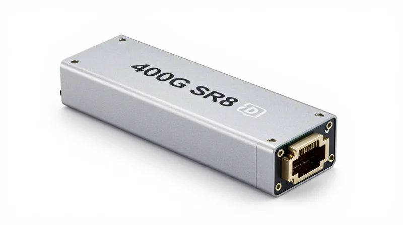
400G SR8 is an optical communication standard defined under the IEEE 802.3cm task force, specifically engineered to deliver 400 Gigabit Ethernet (GbE) throughput over short distances. It serves as a foundational component in the hyperscale cloud roadmap, facilitating high-bandwidth connectivity within data center racks or across short-span rows. By utilizing eight distinct lanes of 50 Gbps PAM4 (Pulse Amplitude Modulation 4-level) signaling, SR8 provides a cost-effective and power-efficient migration path for operators transitioning from 100G to 400G infrastructure without requiring immediate jumps to more expensive single-mode optics.
Decoding the SR8 Designation
The nomenclature 'SR8' provides direct insight into its physical layer architecture. The 'SR' prefix stands for 'Short Reach,' indicating the standard is optimized for multimode fiber (MMF) deployments. The numeral '8' refers to the eight parallel optical lanes that aggregate to form the 400G pipe. Unlike other 400G variants like DR4 or FR4, which utilize four 100G lanes, SR8 leverages the maturity of 50G PAM4 electronics. This 8-lane approach reduces the complexity and power consumption of the transceiver's Digital Signal Processor (DSP), making it a highly reliable choice for high-radix switch interconnects.
Technical Specifications and Operational Parameters
| Parameter | Standard Specification |
|---|---|
| IEEE Standard | 802.3cm |
| Reach (OM3 Fiber) | Up to 70 Meters |
| Reach (OM4/OM5 Fiber) | Up to 100 Meters |
| Modulation Type | 50G PAM4 |
| Lane Count | 8 Tx / 8 Rx Lanes |
| Connector Types | MPO-16 or MPO-24 |
The Strategic Role of SR8 in Cloud Networking
In the context of modern cloud data centers, 400G SR8 is primarily deployed for leaf-to-spine links and high-speed server access where reach requirements are typically under 100 meters. Its most significant advantage lies in its breakout capabilities. Because it utilizes eight discrete lanes, a single 400G SR8 port can be seamlessly broken out into 8x50G or 2x200G connections. This flexibility is essential for multi-tenant environments where switch ports must serve varying generations of network interface cards (NICs) across different server nodes.
Frequently Asked Questions
- Does 400G SR8 support breakout configurations?
Yes, SR8 is natively designed to support breakouts, allowing a single 400G port to connect to multiple 50G or 100G endpoints, which maximizes port density and cable management efficiency. - Is 400G SR8 compatible with Single-Mode Fiber (SMF)?
No, SR8 is strictly a Multimode Fiber (MMF) standard. For Single-Mode applications, standards such as 400G DR4 or FR4 must be used. - What is the primary difference between SR8 and SR4.2?
SR8 uses 8 parallel lanes of 50G over 16 fibers (total), while SR4.2 uses bidirectional signaling to transmit 100G per pair over 4 pairs of fiber (8 fibers total). SR8 is often preferred for its simpler optical design and lower DSP overhead.
Technical Architecture: The Power of PAM4 Modulation

The transition to 400G SR8 is fundamentally driven by the shift from traditional Non-Return-to-Zero (NRZ) signaling to 4-level Pulse Amplitude Modulation (PAM4). While NRZ uses two voltage levels to represent a single bit, PAM4 utilizes four distinct signal levels (00, 01, 10, 11) to transmit two bits per symbol. This architectural shift allows 400G SR8 to achieve a 50Gbps data rate per lane using the same physical baud rate as a 25G NRZ signal, effectively doubling the capacity of the fiber infrastructure without requiring a proportional increase in optical bandwidth.
Comparing NRZ and PAM4 Signaling
| Parameter | NRZ (2-level) | PAM4 (4-level) |
|---|---|---|
| Signal Levels | 2 (High/Low) | 4 (0, 1, 2, 3) |
| Bits Per Symbol | 1 Bit | 2 Bits |
| Data Rate at 25GBaud | 25 Gbps | 50 Gbps |
| Signal-to-Noise Ratio (SNR) | High Margin | Reduced (~9.5dB loss) |
| Error Correction | Optional/Basic | Mandatory (KP4 FEC) |
The 8-Lane Parallel Architecture
The '8' in 400G SR8 refers to the eight parallel lanes utilized for both transmission and reception. By combining PAM4 modulation with this eight-lane configuration, the system achieves 400Gbps aggregate throughput. Each lane operates at a symbol rate of approximately 26.56 Gbaud. Because PAM4 carries two bits per symbol, each lane delivers a raw bit rate of 53.125 Gbps. When all eight lanes are synchronized over an MPO-16 connector, the data center fabric gains a robust, high-density 400G link capable of supporting the massive I/O requirements of modern AI and cloud workloads.
The Role of DSP and FEC
Due to the reduced signal spacing in PAM4, the waveform is more sensitive to optical noise and dispersion. To counteract this, 400G SR8 transceivers employ a sophisticated Digital Signal Processor (DSP) and Forward Error Correction (FEC). The DSP handles the complex task of equalizing the PAM4 signal, while the KP4 FEC algorithm identifies and corrects bit errors in real-time. This ensures that despite the increased complexity of the modulation, the Bit Error Rate (BER) remains within the strict tolerances required for reliable cloud networking.
- Why was PAM4 chosen over increasing lane counts?
Increasing the number of NRZ lanes to 16 to reach 400G would have resulted in excessive power consumption, larger module form factors, and prohibitively expensive cabling costs. - Does PAM4 increase the reach of SR8?
No, PAM4 is more sensitive to signal degradation than NRZ, which is why SR8 is specifically designed for short-reach (SR) applications up to 100 meters over OM4 fiber. - What is the impact of PAM4 on latency?
The inclusion of FEC and DSP for PAM4 processing introduces a slight amount of latency (nanoseconds), which is generally negligible for most cloud applications but a consideration for High-Performance Computing (HPC).
Optical Connectivity: MPO-16 and Fiber Infrastructure
Optical Connectivity: MPO-16 and Fiber Infrastructure
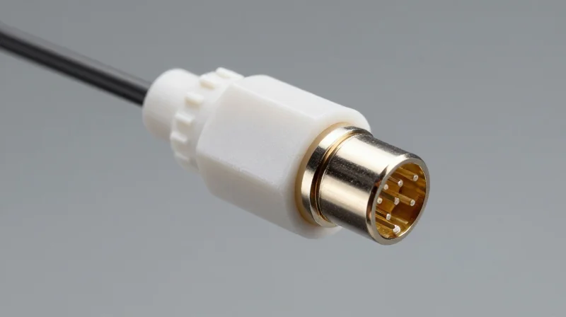
400G SR8 utilizes an 8-lane parallel architecture that necessitates the adoption of MPO-16 (Multi-fiber Push-On) connectors, providing 16 discrete fibers to support simultaneous 8-channel transmit and 8-channel receive paths. Unlike previous generations that often relied on MPO-12 with 'dark' unused fibers, the MPO-16 interface is purpose-built to maximize density and maintain the strict signal integrity required for 50G PAM4 optical signals over multi-mode fiber (MMF).
The Shift to MPO-16 Connectors
In the evolution of data center interconnects, the MPO-12 connector was the workhorse for 40G and 100G SR4. However, 400G SR8 requires eight pairs of fibers. While two MPO-12 connectors could technically be used, the industry has standardized on a single-row MPO-16 or a dual-row MPO-16 (2x8) to streamline cable management and reduce the transceiver footprint. The MPO-16 connector features a unique offset keying mechanism to prevent accidental mating with MPO-12 hardware, ensuring that the 16-fiber array aligns perfectly with the VCSEL (Vertical-Cavity Surface-Emitting Laser) array in the transceiver.
Fiber Media Performance: OM3, OM4, and OM5
The reach and reliability of 400G SR8 are heavily dependent on the grade of multi-mode fiber used. As data rates climb to 50G per lane, chromatic dispersion and modal bandwidth become limiting factors. While OM3 and OM4 are common in existing brownfield installations, OM5 (Wideband Multimode Fiber) is increasingly preferred for its optimized performance in high-speed environments.
| Fiber Type | Effective Modal Bandwidth | 400G SR8 Reach Support | Color Code |
|---|---|---|---|
| OM3 | 2000 MHz*km | Up to 70 meters | Aqua |
| OM4 | 4700 MHz*km | Up to 100 meters | Erika Violet / Aqua |
| OM5 | 4700 MHz*km (Optimized) | Up to 100 meters | Lime Green |
High-Precision Alignment and Signal Integrity
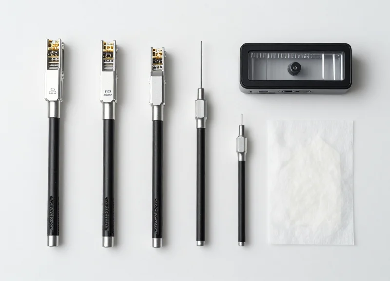
The move to PAM4 modulation significantly reduces the signal-to-noise ratio (SNR) margin compared to traditional NRZ. Consequently, the physical connection point becomes a primary source of potential failure. High-precision fiber alignment within the MPO-16 ferrule is critical to minimize insertion loss (IL) and return loss (RL). Even minute dust particles or slight axial misalignments can cause bit errors that the system's Forward Error Correction (FEC) cannot overcome. Implementing rigorous 'inspect, clean, and connect' protocols is no longer optional in 400G environments; it is a technical necessity.
- Can I use MPO-12 patch cables for 400G SR8?
No, 400G SR8 transceivers specifically require a 16-fiber MPO interface. MPO-12 cables do not have the fiber count or the correct keying to mate with SR8 ports. - Why is OM5 recommended if the reach is the same as OM4?
While the reach for SR8 is currently capped at 100m for both, OM5 provides better performance margins and is future-proofed for Shortwave Wavelength Division Multiplexing (SWDM) technologies. - What is the primary cause of link failure in SR8 connectivity?
Contamination on the MPO-16 end-face is the most common cause, as the high density of fibers increases the likelihood that dust will obstruct one or more of the eight active lanes.
Performance Metrics: Power Consumption and Thermal Management
In the hyperscale cloud environment, 400G SR8 modules are prized for their superior power efficiency, typically consuming significantly less energy per gigabit than their single-mode counterparts. By leveraging Vertical-Cavity Surface-Emitting Laser (VCSEL) technology, SR8 modules minimize the electrical-to-optical conversion loss, though they present unique thermal management challenges within high-density QSFP-DD and OSFP ports due to the heat generated by the 7nm or 5nm Digital Signal Processors (DSPs).
Power Efficiency: VCSEL vs. Silicon Photonics
The 400G SR8 architecture is inherently more power-efficient than long-reach optics because it utilizes VCSELs rather than Electro-absorption Modulated Lasers (EML) or Silicon Photonics. Because SR8 operates over shorter distances, the link budget requirements are lower, allowing the laser drivers to operate at reduced bias currents. However, the integration of 8 channels of PAM4 DSPs remains the primary contributor to the power envelope, requiring careful balance between signal integrity and energy draw.
| Module Type | Typical Power Consumption | Laser Technology | Max Reach |
|---|---|---|---|
| 400G SR8 | 7.5W - 9.0W | VCSEL (850nm) | 100m (OM4) |
| 400G DR4 | 9.0W - 11.0W | Silicon Photonics / EML | 500m (SMF) |
| 400G FR4 | 10.0W - 12.0W | EML / TOSA | 2km (SMF) |
Thermal Management in QSFP-DD and OSFP
Thermal dissipation is a critical factor in maintaining the reliability of 400G SR8 transceivers. The industry-standard QSFP-DD (Quad Small Form-factor Pluggable Double Density) and OSFP (Octal Small Form-factor Pluggable) designs handle heat differently. While QSFP-DD relies on the host system's heatsink and airflow, the OSFP form factor includes integrated fins on the module itself, providing a larger surface area for cooling. In a fully loaded 32-port 1U switch, the cumulative thermal load can exceed 300W, necessitating advanced airflow modeling to prevent DSP throttling.
The Impact of DSP Heat Flux
As SR8 modules move to smaller process nodes (from 16nm to 7nm and 5nm), the power per gigabit drops, but the heat flux—the amount of heat generated in a small area—increases. This concentrated heat can lead to 'hot spots' on the optical bench, potentially shifting the VCSEL wavelength or reducing the lifespan of the optical components if the case temperature exceeds the standard 70°C operating limit.
Thermal and Power Performance FAQ
- Why does 400G SR8 consume less power than 400G DR4?
SR8 uses multi-mode VCSELs which require lower drive currents and lack the complex external modulators or high-power silicon photonics circuits required for single-mode fiber transmission. - What happens if a 400G SR8 module overheats?
The module's internal firmware will typically trigger a thermal alarm via the I2C interface. If temperatures continue to rise, the DSP will lower its clock speed or shut down to protect the internal circuitry from permanent damage. - Does the use of MPO-16 affect cooling?
Indirectly. High-density MPO-16 cabling can obstruct airflow at the front of the switch if cable management is poor, leading to higher ambient temperatures around the optical ports.
400G SR8 vs. 400G DR4: A Comparative Analysis
400G SR8 vs. 400G DR4: A Comparative Analysis
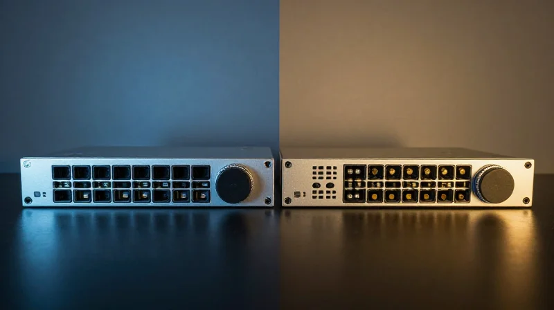
The fundamental difference between 400G SR8 and 400G DR4 lies in the lane architecture and the physical medium: SR8 utilizes an 8-lane 50G PAM4 configuration over multi-mode fiber (MMF) for short-range cost savings, whereas DR4 employs a 4-lane 100G PAM4 configuration over single-mode fiber (SMF) to support longer reach and 100G breakout capabilities. While SR8 provides the most economical entry point for high-density, short-reach interconnects within a rack, DR4 offers superior scalability and lower cabling complexity for inter-rack and leaf-spine connectivity.
Technical and Hardware Specifications
| Feature | 400G SR8 | 400G DR4 |
|---|---|---|
| Modulation | 8 x 50G PAM4 | 4 x 100G PAM4 |
| Fiber Type | Multi-mode (OM3/OM4/OM5) | Single-mode (OS2) |
| Max Distance | 100m (OM4/OM5) | 500m |
| Connector | MPO-16 or MPO-24 | MPO-12 |
| Breakout Mode | 8x50G | 4x100G |
Reach and Media Considerations
400G SR8 is designed for the high-density requirements of the server-to-ToR (Top-of-Rack) layer, where distances rarely exceed 100 meters. By using multi-mode fiber, SR8 leverages lower-cost VCSEL (Vertical-Cavity Surface-Emitting Laser) technology. In contrast, 400G DR4 utilizes single-mode fiber and silicon photonics or EML (Electro-absorption Modulated Laser) technology. Although the transceivers for DR4 are generally more expensive due to these precision components, the single-mode fiber itself is cheaper and provides a much cleaner migration path to 800G and 1.6T speeds.
Total Cost of Ownership (TCO) and Breakout Capability
When calculating TCO, operators must balance the module cost against the cabling infrastructure. SR8 requires a 16-fiber MPO-16 cable, which is more complex and expensive to manage than the 12-fiber MPO-12 used by DR4. Furthermore, DR4 is often favored in cloud architectures because it can natively break out into four 100G-DR modules. This allows for seamless interoperability between 400G switches and 100G servers, a feature that SR8—which breaks out into 50G increments—cannot match without additional gearbox complexity.
Comparison FAQs
- Can 400G SR8 connect directly to 400G DR4?
No. They use different fiber types (multi-mode vs. single-mode) and different lane speeds (50G vs. 100G PAM4), making them optically incompatible. - Which module is more power-efficient?
Generally, SR8 modules consume slightly less power because VCSEL lasers are more energy-efficient than the silicon photonics or EMLs required for DR4's 500m reach. - Why choose SR8 over DR4 if the distance is short?
The primary driver is the initial capital expenditure on transceivers; for very large-scale deployments where distances are under 70m, the savings on SR8 modules can be significant.
Deployment Scenarios in Hyperscale Cloud Data Centers

In modern hyperscale cloud data centers, 400G SR8 serves as the workhorse for high-bandwidth, short-reach connectivity, enabling the transition to flattened, non-blocking network architectures. By utilizing parallel multi-mode fiber, SR8 provides a cost-optimized path for scaling switch-to-switch links within a 100-meter range, which covers the vast majority of intra-data center connections in standardized Clos topologies.
Leaf-to-Spine Interconnects in Flattened Fabrics
Hyperscale operators have largely moved away from traditional three-tier hierarchical models in favor of flattened leaf-spine (Clos) architectures. In this model, 400G SR8 modules are deployed at the leaf layer to aggregate massive amounts of server traffic and uplink it to the spine layer. Because these links are typically contained within a single hall or adjacent rows, the 100m reach of SR8 over OM4 fiber is perfectly suited for these high-density interconnects, offering significant power savings over single-mode alternatives.
| Deployment Scenario | Typical Distance | Primary Benefit | Cabling Type |
|---|---|---|---|
| Intra-Rack (ToR to Server) | 1m - 5m | High-speed AI/ML cluster connectivity | DAC/AOC or MPO-16 MMF |
| Inter-Rack (Leaf to Spine) | 10m - 100m | Low-latency fabric scaling | OM4/OM5 Multi-mode Fiber |
| Breakout Mode | Variable | Backwards compatibility with 50G/100G | MPO-16 to 8x LC/SN |
Breakout Flexibility for Incremental Upgrades
A critical advantage of the 8-lane architecture of 400G SR8 is its inherent support for breakout configurations. A single 400G SR8 port can be configured as 8x 50G or 2x 200G links. This allows cloud providers to upgrade their spine switches to 400G while still supporting legacy 50G or 100G leaf switches. This granular control over port density enables a phased migration to 400G without requiring a simultaneous forklift upgrade of the entire network infrastructure.
Deployment FAQ
- Why is SR8 preferred over DR4 for intra-row connections?
SR8 utilizes multi-mode vertical-cavity surface-emitting lasers (VCSELs), which are significantly cheaper to manufacture and consume less power than the silicon photonics or EML lasers used in 400G DR4 single-mode modules. - How does SR8 impact cable management in hyperscale facilities?
The use of MPO-16 connectors requires high-precision cable management and clean fiber end-faces. While the cable count is higher than 4-lane solutions, the cost-per-bit advantage for short reaches often outweighs the complexity for cloud operators. - Can 400G SR8 support AI/ML workloads?
Yes, it is increasingly used in AI/ML backend networks where low latency and massive throughput are required between GPU-heavy compute nodes and specialized leaf switches.
Interoperability and Backward Compatibility Challenges
The primary interoperability challenge for 400G SR8 lies in its 8-lane 50G PAM4 electrical and optical interface, which must often communicate with legacy systems based on 25G NRZ or 100G single-wavelength technologies. While the 8-lane parallel design of SR8 is inherently suited for breakout applications, ensuring seamless data flow requires a precise alignment of physical connectors, port logic, and firmware settings across the networking stack.
Breakout Scenarios and Physical Connectivity
Breakout cabling is the most common method for achieving backward compatibility. Because 400G SR8 uses an MPO-16 (or MPO-24) connector to manage its eight pairs of fibers, it can be logically split into multiple lower-speed connections. However, this requires the switch hardware to support 'port splitting' at the firmware level to correctly map the internal SerDes lanes.
| Breakout Type | Connector (400G Side) | Connector (Legacy Side) | Legacy Port Compatibility |
|---|---|---|---|
| 1x400G to 2x200G | MPO-16 | 2x MPO-8/MPO-12 | 200G SR4 (PAM4) |
| 1x400G to 4x100G | MPO-16 | 4x MPO-8/MPO-12 | 100G SR2 (PAM4) |
| 1x400G to 8x50G | MPO-16 | 8x LC Duplex | 50G SR (PAM4) |
The FEC Mismatch Problem
A significant hurdle in 400G SR8 interoperability is the mandatory use of IEEE 802.3bs Forward Error Correction (RS-FEC). Legacy 100G SR4 modules often utilize different FEC standards (like RS-FEC 528) or operate without FEC entirely. When attempting a breakout from a 400G SR8 port to 100G ports, the link will fail to initialize if the FEC settings on both ends are not perfectly synchronized. Network administrators must manually verify that the legacy equipment can support the KP4 FEC required by the 50G PAM4 lanes used in SR8.
Firmware and Auto-Negotiation Challenges
Auto-negotiation across 400G SR8 links remains complex. Many older 100G or 200G switches lack the updated firmware to recognize the 50G PAM4 signaling scheme. Without a firmware update, the switch may default to NRZ signaling or fail to recognize the transceiver EEPROM, leading to 'port disabled' states. Furthermore, the power consumption of SR8 modules (up to 12W) can exceed the thermal or electrical budget of older QSFP-DD ports that were designed for lower-wattage optics.
- Can 400G SR8 connect directly to 100G SR4?
No, they are incompatible. 400G SR8 uses 50G PAM4 modulation, while 100G SR4 uses 25G NRZ. A gearbox or a switch capable of multi-rate modulation is required for such a connection. - What is the primary risk of using legacy MPO-12 cables with SR8?
Standard MPO-12 cables only have 12 fibers, whereas SR8 requires 16 fibers for its 8-lane bi-directional traffic. Using the wrong cable will result in four lanes being physically disconnected. - How is the reach affected in breakout mode?
The reach is generally limited by the weakest link, usually 70m to 100m over OM4 fiber, consistent with standard 400G SR8 specifications regardless of breakout configuration.
The Future of Optical Interconnects: Beyond 400G

The Path from 400G to 800G and Beyond
The transition beyond 400G SR8 is not merely a speed increase but a fundamental shift in how high-density optical lanes are managed and powered within the hyperscale data center. While 400G SR8 established the viability of 8-lane parallel multimode structures, the industry is now moving toward 800G and 1.6T by doubling the per-lane baud rate and exploring Co-Packaged Optics (CPO) to overcome the physical and thermal limitations of traditional pluggable modules.
The Legacy of SR8 in 800G Architectures
The lessons learned from 400G SR8—specifically regarding MPO-16 cabling density and the reliability of Vertical-Cavity Surface-Emitting Lasers (VCSELs)—are currently being applied to 800G SR8 standards. By upgrading the SerDes from 56G to 112G per lane, the industry can maintain the 8-lane form factor while doubling the aggregate bandwidth. This approach allows for a relatively smooth upgrade path for cloud providers who have already invested in the MPO-16 infrastructure required for 400G SR8.
| Feature | 400G SR8 | 800G SR8 | 1.6T (Predicted) |
|---|---|---|---|
| Lanes | 8 Lanes | 8 Lanes | 16 Lanes or 8x200G |
| Per-Lane Speed | 50G (PAM4) | 100G (PAM4) | 200G (PAM4/Next-Gen) |
| Connector Type | MPO-16 / MPO-24 | MPO-16 | Advanced MPO / SN-MT |
| Max Reach (OM4) | 100m | 50m - 100m | Under 50m |
Emerging Technologies: LPO and CPO
As speeds reach 1.6T, the power consumption of the Digital Signal Processor (DSP) within pluggable modules becomes a significant bottleneck. Linear Drive Pluggable Optics (LPO) and Co-Packaged Optics (CPO) are emerging as the primary solutions to this challenge. LPO removes the power-hungry DSP from the module, relying on the switch ASIC's signal integrity, while CPO moves the optical engine directly onto the switch package, drastically reducing the electrical trace length and power dissipation.
- Will multimode fiber (SR) remain relevant at 1.6T?
Multimode fiber will likely remain dominant for very short-reach links (under 50m) due to its cost-effectiveness, but single-mode solutions (DR) are expected to capture more of the market as distances and signal integrity requirements increase. - What is the role of 200G-per-lane technology?
200G SerDes is the next major milestone, enabling 1.6T aggregate throughput using 8 lanes, which will significantly reduce the complexity compared to using 16 lanes of 100G. - How does AI impact the transition beyond 400G?
AI/ML clusters require massive East-West traffic bandwidth and ultra-low latency, accelerating the adoption of 800G and 1.6T interconnects much faster than general-purpose cloud computing.
Navigating the complexities of 400G SR8 is essential for any IT leader looking to scale cloud infrastructure efficiently. By balancing cost-effective multi-mode fiber with advanced PAM4 modulation, SR8 remains a cornerstone of high-speed networking. To ensure your network is ready for the next generation of data demands, contact our specialist team today for a customized optical roadmap evaluation.