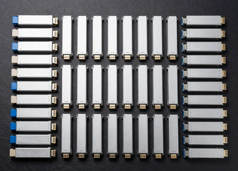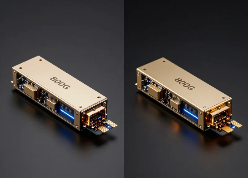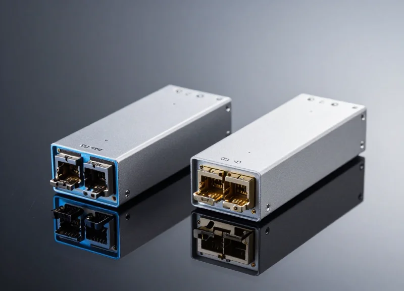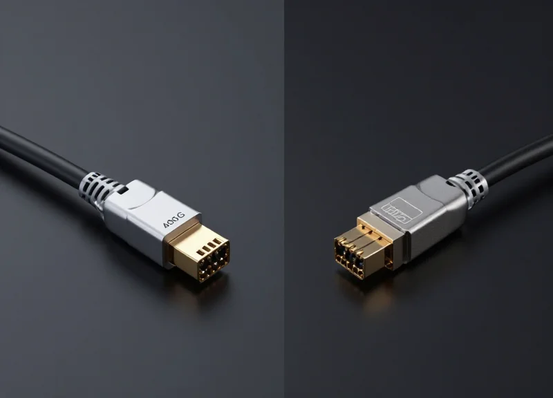
As data-intensive workloads like AI and machine learning push existing infrastructure to its limits, data center architects face a critical decision: stay with 100G, pivot to 200G, or leap directly to 400G. This guide provides a veteran's perspective on why the 400G migration is the definitive path for performance and cost-efficiency.
The Evolution of Bandwidth: Why 100G is No Longer Enough

The transition from 100G to 400G is primarily driven by a fundamental shift in how data is consumed and processed at the network core. While 100G Ethernet provided a stable foundation for the cloud expansion of the 2010s, it has become a significant bottleneck in an era defined by massive AI model training, hyperscale virtualization, and the proliferation of high-bandwidth video traffic. Simply adding more 100G ports is no longer a viable scaling strategy due to the physical limitations of rack space, power consumption, and the complexity of managing massive link aggregation groups.
The Catalysts of Bandwidth Exhaustion
The primary pressure points on 100G infrastructure stem from two main sectors: Artificial Intelligence (AI) and Machine Learning (ML). These workloads require vast amounts of East-West traffic within the data center, often involving the transfer of terabytes of parameter data between GPU clusters. Additionally, the move toward 4K and 8K video streaming, combined with the low-latency requirements of 5G and edge computing, has pushed the edge of the network to require throughput levels that only 400G and beyond can reliably provide.
| Feature | 100G Ethernet | 400G Ethernet |
|---|---|---|
| Max Throughput | 100 Gbps | 400 Gbps |
| Modulation Type | NRZ / PAM4 | PAM4 (Pulse Amplitude Modulation) |
| Typical Lanes | 4 x 25G / 2 x 50G | 8 x 50G / 4 x 100G |
| Power Efficiency | Higher Watts per Gbps | Lower Watts per Gbps (Optimized) |
| Primary Use Case | Enterprise Core / Legacy DC | Hyperscale DC / AI Clusters |
The Performance Gap: Density and Efficiency
Beyond raw speed, the 400G migration is a play for operational efficiency. 400G optics and switches utilize PAM4 signaling, which doubles the data rate per clock cycle compared to traditional NRZ signaling. This allows network architects to achieve higher density—fitting more bandwidth into a single 1U rack space—while simultaneously reducing the total cost of ownership (TCO) through lower power consumption per bit transferred. As power costs and cooling requirements become critical constraints for data center expansion, the energy efficiency of 400G becomes its most compelling advantage over legacy 100G stacks.
Frequently Asked Questions
- Is 100G still relevant for smaller enterprises?
Yes, 100G remains a viable and cost-effective solution for standard enterprise branch offices and smaller data centers where the aggregate traffic does not yet justify the premium of 400G hardware. - Why skip 200G and go straight to 400G?
While 200G exists as an intermediary, many organizations prefer 400G because it offers a more significant leap in density and a longer lifecycle, providing a better long-term return on investment (ROI). - What are the main hardware requirements for a 400G migration?
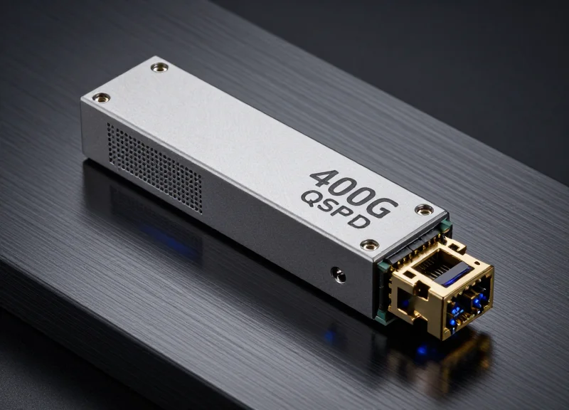
The migration typically requires new switches with high-density QSFP-DD or OSFP ports, compatible transceivers, and often an upgrade to high-quality MPO/MTP fiber cabling to support the increased lane counts.
Evaluating the Alternatives: The Case for 200G and Multi-Link 100G
Evaluating the Alternatives: The Case for 200G and Multi-Link 100G
Intermediate solutions like 200G or multi-link 100G configurations are frequently implemented as tactical responses to immediate bandwidth pressure, yet they often represent a false economy in high-performance environments. While these paths allow organizations to leverage existing 100G-centric hardware or bridge the gap to 400G, they invariably lead to increased operational complexity, higher power consumption per gigabit, and a fragmented physical layer that is difficult to manage at scale. Choosing an intermediate path is essentially a trade-off between lower initial capital expenditure and the long-term architectural purity required to support AI and data-intensive workloads.
The Complexity of Multi-Link 100G (Link Aggregation)
Bonding multiple 100G links using Link Aggregation Groups (LAG) or Equal-Cost Multi-Path (ECMP) routing is a common method to increase throughput without upgrading to a new Ethernet standard. However, this 'horizontal' scaling method hits a ceiling of diminishing returns. As the number of 100G links increases, so does the complexity of load balancing and the risk of packet reordering issues. Furthermore, using four 100G ports to achieve the equivalent throughput of a single 400G port consumes four times the rack space and significantly more power, making it an unsustainable strategy for modern, high-density data centers.
| Metric | Multi-Link 100G (4x100G) | 200G Ethernet (2x100G/4x50G) | 400G Ethernet (Native) |
|---|---|---|---|
| Port Utilization | High (4 ports) | Moderate (1-2 ports) | Low (1 port) |
| Cabling Density | High / Complex | Moderate | Low / Simplified |
| Power Efficiency | Lowest | Moderate | Highest |
| Management Overhead | High (Logical Bonding) | Moderate | Low (Single Interface) |
| Future Scalability | Very Limited | Limited | Excellent |
The Strategic Risk of 200G Deployments
200G Ethernet was originally conceived as a mid-point standard, utilizing 50G PAM4 signaling to double 100G speeds. While it provides a performance boost, its market adoption has been overshadowed by the rapid maturation of 400G. Investing in 200G infrastructure often places an organization in a 'niche' ecosystem where transceiver options are more limited and the price-per-bit does not drop as quickly as it does for the high-volume 400G market. For many enterprises, 200G becomes a technical dead-end that requires another full rip-and-replace cycle much sooner than a direct jump to 400G would have necessitated.
- Is 200G more cost-effective than 400G?
In the very short term, 200G may require less initial investment in optics and switches; however, the higher price-per-bit and shorter lifecycle often make 400G more cost-effective over a three-to-five-year horizon. - Can Link Aggregation (LAG) effectively replace a 400G upgrade?
No. While LAG increases aggregate throughput, it cannot increase the speed of a single flow, and the physical overhead of cabling and power usually outweighs the benefits of avoiding a hardware refresh. - When does an intermediate solution make sense?
Intermediate solutions are only logical when existing hardware backplanes cannot support 400G speeds and the budget for a total fork-lift upgrade is strictly unavailable for the current fiscal cycle.
Latency Analysis: PAM4 vs. NRZ Modulation

While the migration from 100G to 400G dramatically increases total throughput, it necessitates a shift from Non-Return to Zero (NRZ) to Pulse Amplitude Modulation 4-level (PAM4). The fundamental difference is that while PAM4 doubles the data density per clock cycle, it introduces a 'latency tax' primarily due to the requirement for Forward Error Correction (FEC) to manage the decreased signal-to-noise ratio inherent in four-level signaling.
NRZ vs. PAM4: The Architecture of the Signal
NRZ modulation, the standard for 100G, is a binary signaling technique using two voltage levels to represent 0 and 1. It is robust and simple, allowing for high signal integrity over longer distances without complex processing. Conversely, PAM4 uses four distinct signal levels to represent two bits of data per symbol (00, 01, 10, 11). This effectively doubles the bandwidth within the same baud rate but makes the signal significantly more susceptible to noise and interference.
| Metric | NRZ (100G) | PAM4 (400G) |
|---|---|---|
| Voltage Levels | 2 Levels (Binary) | 4 Levels (Quaternary) |
| Bits per Symbol | 1 Bit | 2 Bits |
| Signal-to-Noise Ratio (SNR) | High | Low (-9.5 dB penalty) |
| FEC Requirement | Optional/Minimal | Mandatory |
| Approx. FEC Latency | < 10 ns | 100 ns to 250 ns |
The FEC Factor: Why 400G is 'Slower' in Nanoseconds
In 400G ecosystems, the eyes of the PAM4 signal are much smaller than those in NRZ, leading to a higher Bit Error Rate (BER). To achieve reliable data transmission, hardware manufacturers must implement Forward Error Correction (FEC) algorithms. These algorithms add a mathematical overhead at both the transmitting and receiving ends to detect and fix errors without retransmission. For standard Ethernet applications, this 100-250ns delay is negligible, but for specialized environments, it represents a significant shift in performance profiles.
Latency Implications for High-Frequency Trading (HFT)
In the world of HFT, where profits are measured in microseconds, the mandatory FEC latency of 400G PAM4 can be a deterrent. Many ultra-low-latency firms continue to utilize 100G NRZ or look for specialized 'FEC-light' or 'no-FEC' proprietary 200G/400G solutions. The trade-off is often a reduction in reach (cable length) to maintain signal integrity without the mathematical safety net of FEC.
AI Training and Hyperscale Data Centers
For AI and Machine Learning (ML) workloads, throughput is generally more critical than the nanosecond-level latency added by PAM4. The massive data sets required for Large Language Model (LLM) training benefit far more from the 400G bandwidth 'pipe' than they are hindered by the minor processing delay of error correction.
- Is PAM4 latency noticeable in standard enterprise apps?
No. For 99% of enterprise applications, including database queries and web traffic, a 150ns delay is statistically invisible compared to the gains in total throughput. - Can 400G run without FEC to reduce latency?
Generally, no. Without FEC, the Bit Error Rate of a standard PAM4 signal is too high for reliable communication over any meaningful distance. - Does 800G use the same modulation?
Yes, 800G currently relies on PAM4, meaning the latency characteristics remain similar to 400G, though research into PAM6 and PAM8 is ongoing for future iterations.
Power Consumption: Solving the Efficiency Per Gigabit Puzzle

The Efficiency Breakthrough: Power-to-Bandwidth Ratios
The transition to 400G represents a critical pivot point in data center economics where power efficiency becomes a primary driver for hardware selection. While a 400G QSFP-DD transceiver consumes more absolute power than a 100G QSFP28 module, it delivers four times the bandwidth for roughly twice the power consumption. This efficiency is achieved through the integration of 7nm DSPs (Digital Signal Processors) and the transition from NRZ to PAM4 modulation, which allows for higher data density without a linear increase in electrical overhead. Consequently, operators can expect a 40% to 50% reduction in power consumption per gigabit compared to legacy 100G infrastructure.
| Optic Standard | Typical Power Consumption | Bandwidth | Efficiency (Watts/Gbps) |
|---|---|---|---|
| 100G QSFP28 (LR4) | 4.5W | 100 Gbps | 0.045 W/Gbps |
| 4x 100G (Bonded) | 18.0W | 400 Gbps | 0.045 W/Gbps |
| 200G QSFP56 (FR4) | 7.5W | 200 Gbps | 0.037 W/Gbps |
| 400G QSFP-DD (DR4) | 12.0W | 400 Gbps | 0.030 W/Gbps |
Impact on Cooling and Infrastructure OpEx
Lower power consumption per bit has a cascading effect on the entire data center ecosystem. Every watt saved at the transceiver level reduces the heat dissipation requirements, leading to secondary savings in cooling infrastructure and fan energy consumption. In high-density environments, utilizing 400G optics allows for a consolidated port count, which improves airflow within the chassis and reduces the total thermal load per rack. This consolidation is often the only way for hyperscale facilities to scale capacity within their existing power and cooling envelopes.
Common Efficiency Inquiries
- Does 400G migration require upgrading existing PDUs?
In most cases, 400G reduces the total power draw for the same aggregate bandwidth, meaning existing Power Distribution Units (PDUs) can often support the migration while actually gaining headroom for additional equipment. - How does the 400G DSP affect heat dissipation?
The DSP in 400G modules is the primary heat source. However, 7nm and 5nm CMOS technology in modern 400G designs are significantly more efficient than the older silicon used in 100G modules, leading to lower heat generation per bit processed. - Is the power saving significant enough to justify the CAPEX?
For large-scale deployments, the reduction in electricity and cooling costs (OpEx) typically provides a return on investment (ROI) within 18 to 24 months, especially in regions with high energy costs.
Total Cost of Ownership (TCO): CapEx and OpEx Breakdown
Total Cost of Ownership (TCO): CapEx and OpEx Breakdown
Transitioning from 100G to 400G is not merely a hardware upgrade; it is a strategic shift in the economic structure of the data center. While the initial capital expenditure (CapEx) for 400G platforms remains higher per port than legacy 100G equipment, the cost per gigabit is significantly lower. When amortized over a standard 3-to-5-year lifecycle, the operational expenditure (OpEx) savings—driven primarily by a 75% reduction in rack space and a 50% improvement in power-to-bandwidth efficiency—create a break-even point typically within the first 18 to 24 months of deployment.
CapEx: Analyzing the Premium on 400G Optics and Silicon
The primary CapEx drivers for 400G migration are the QSFP-DD/OSFP transceivers and high-density switches (e.g., 12.8Tbps or 25.6Tbps ASICs). Currently, 400G optics account for roughly 50-60% of the total hardware bill of materials. However, opting for a 400G infrastructure replaces the need for four discrete 100G ports, reducing the overall number of physical interfaces and cables required. This consolidation minimizes the 'cost of complexity' associated with managing vast quantities of fiber and patch panels.
| Financial Metric | 100G Legacy (Scaled) | 400G Migration |
|---|---|---|
| Initial Hardware Cost (CapEx) | Lower per unit | Higher per unit (but lower per Gbps) |
| Power Consumption (W/Gbps) | ~0.45W - 0.6W | ~0.2W - 0.3W |
| Rack Space Requirements | 4 Rack Units | 1 Rack Unit |
| Cabling Complexity | High (4x the fiber runs) | Low (Consolidated trunks) |
| Management Overhead | High (More devices/ports) | Low (Fewer managed entities) |
OpEx: The Efficiency Multiplier
Operational savings are the most compelling argument for 400G. By utilizing high-density 400G switches, operators can support the same bandwidth as four 100G switches in a fraction of the power envelope. This reduces heat dissipation requirements, lowering the energy consumed by cooling infrastructure (PUE efficiency). Furthermore, the reduction in physical footprint allows providers to defer expensive facility expansions, effectively extending the life of existing data center halls.
- How does 400G affect the price-per-bit over time?
As manufacturing volumes for PAM4-based optics increase, the price-per-bit for 400G is declining faster than 100G NRZ, making it the more sustainable long-term investment. - Is the power savings significant enough to justify the upgrade?
Yes. In large-scale deployments, the 400G architecture reduces power-per-gigabit by over 40%, which translates to millions of dollars in utility savings annually for hyperscale environments. - What is the impact on maintenance costs?
Fewer physical ports and transceivers mean fewer potential points of failure (MTBF improves), reducing the labor costs associated with troubleshooting and hardware replacement.
Cabling and Optical Infrastructure: Preparing the Physical Layer
Cabling and Optical Infrastructure: Preparing the Physical Layer
The migration to 400G represents a paradigm shift in the physical layer, moving away from the MPO-12 standard that defined 100G architectures toward more efficient Base-8 and Base-16 configurations. While 100G optics often utilized 12-fiber MPO connectors with four fibers unused, 400G necessitates higher precision and fiber utilization. The introduction of PAM4 modulation makes the physical layer significantly more sensitive to signal loss and reflection, requiring cleaner, high-performance optical paths and the strategic use of Very Small Form Factor (VSFF) connectors to manage density.
Connector Evolution: MPO-16 vs. VSFF Solutions
To support the massive throughput of 400G, infrastructure must evolve to accommodate different lane configurations. For parallel optics like 400G-SR8, the MPO-16 connector is the new standard, ensuring all 16 fibers (8 transmit, 8 receive) are utilized effectively. However, for data center operators focusing on port breakout and high-density leaf-spine fabrics, VSFF connectors like CS and SN are becoming the preferred choice over traditional LC duplex connectors.
| Infrastructure Type | Connector Standard | Fiber Count | Primary Use Case |
|---|---|---|---|
| Legacy 100G | MPO-12 / LC Duplex | 8 or 12 fibers | 100G SR4 / LR4 standard links |
| 400G Parallel | MPO-16 | 16 fibers | 400G SR8 (High-bandwidth short reach) |
| 400G Breakout | SN or MDC | 2 fibers per duplex | 4x100G breakouts for high-density spine |
| 400G Duplex | CS Connector | 2 fibers | 2x200G configurations and space saving |
The Strategic Role of SN and CS Connectors
VSFF (Very Small Form Factor) connectors like the SN and CS are designed specifically for the QSFP-DD and OSFP form factors. The SN connector allows for four individual duplex pairs within a single transceiver faceplate, enabling direct 4x100G breakouts without the need for complex and bulky breakout cables. This significantly reduces cable congestion at the rack level. The CS connector, meanwhile, is optimized for 2x200G applications, offering a 40% density increase over traditional LC connectors while maintaining the familiarity of a duplex interface.
Physical Layer Migration FAQ
- Can I reuse my existing MPO-12 fiber plant for 400G?
Yes, but it is typically restricted to 4x100G DR4 applications where only 8 of the 12 fibers are used. For 400G SR8, a transition to MPO-16 or specialized conversion harnesses is required. - Why are SN connectors gaining popularity over MPO breakouts?
SN connectors provide individual control over each duplex pair directly at the transceiver. This simplifies patching, reduces the 'blast radius' during maintenance, and eliminates the need for expensive MPO-to-LC cassettes. - What is the impact of PAM4 on cabling quality?
PAM4 is more susceptible to multipath interference. This means connector cleanliness and return loss (ORL) are more critical than ever; even minor dust particles can cause significant bit error rate (BER) spikes in 400G links.
AI and ML Workload Compatibility

AI and ML Workload Compatibility: Why 400G is the New Baseline
For modern Artificial Intelligence (AI) and Machine Learning (ML) environments, the migration from 100G to 400G is not merely a capacity upgrade; it is a fundamental requirement for maintaining high GPU utilization. Large Language Models (LLMs) and complex neural networks rely on massive distributed computing clusters where data transfer speeds directly dictate the training time. At 100G, the network often becomes the primary bottleneck, forcing expensive GPUs to sit idle while waiting for parameter synchronization across the cluster. 400G provides the necessary throughput to match the input/output capabilities of current-generation accelerators like the NVIDIA H100, ensuring that the fabric can handle the 'all-reduce' and 'all-to-all' communication patterns inherent in deep learning.
RDMA and Low-Latency Performance for Distributed Training
Distributed AI training relies heavily on Remote Direct Memory Access (RDMA), specifically RoCE v2 (RDMA over Converged Ethernet) or InfiniBand. These protocols bypass the CPU to allow direct memory access between nodes, significantly reducing latency and CPU overhead. While 100G supports RDMA, the increased density of 400G minimizes the number of hops and physical switches required in a leaf-spine architecture. This reduction in 'tail latency' is critical for synchronous training steps, where the entire cluster moves as fast as its slowest link.
| Metric | 100G Networking | 400G Networking |
|---|---|---|
| GPU Utilization | 60-70% (Network Bottlenecked) | 90-95% (Optimized Throughput) |
| RDMA Capability | Supported (Limited Bandwidth) | Native (High-Performance RoCE/IB) |
| Training Time (LLM) | High (Weeks to Months) | Low (Days to Weeks) |
| Cluster Efficiency | Requires 4x more ports/cables | High-density, low-complexity fabric |
The Economic Impact of GPU Starvation
The capital expenditure of a 400G migration is often offset by the operational savings of increased GPU efficiency. In a typical AI cluster, the cost of GPUs far outweighs the cost of the networking fabric. If a 100G network causes a 20% drop in GPU performance compared to 400G, the 'lost' value of those idle processors can amount to millions of dollars over a single training cycle. 400G ensures that the compute investment is fully realized by providing a non-blocking, wire-speed environment for massive data sets.
- Can multiple 100G links replace a single 400G link for AI?
While link aggregation (LAG) can increase total bandwidth, it introduces complexity in load balancing and increases the probability of packet reordering issues, which are detrimental to RDMA performance. A native 400G link offers lower latency and simpler management for high-concurrency AI traffic. - What is the role of 400G in edge AI inference?
In inference applications, 400G allows for the rapid ingestion of real-time data streams from thousands of sources, enabling low-latency decision-making for autonomous systems and large-scale video analytics. - Is 400G required for small-scale ML development?
For single-node or small-cluster development, 100G may suffice. However, for any production-level training or scaling to multi-node clusters, 400G is the industry-standard starting point to ensure future-proofing.
Interoperability and Backward Compatibility Challenges
Interoperability and Backward Compatibility Challenges
Migrating to a 400G fabric requires bridging the gap between legacy 100G NRZ signaling and the advanced PAM4 modulation used in 400G transceivers. Ensuring seamless communication across these disparate standards is critical to maintaining network uptime and maximizing the lifespan of existing hardware while avoiding costly 'rip-and-replace' scenarios.
The Modulation Gap: PAM4 vs. NRZ
The primary obstacle in backward compatibility is the transition from Non-Return to Zero (NRZ) signaling, common in most 100G QSFP28 modules, to 4-level Pulse Amplitude Modulation (PAM4) used in 400G. While NRZ handles bits in two voltage levels, PAM4 uses four, doubling the data rate within the same bandwidth. This necessitates the use of 'Gearbox' chips or specialized 100G-PAM4 transceivers that can translate between these formats, often adding slight latency and power overhead.
| Feature | 100G (Legacy) | 400G (Modern) | Compatibility Path |
|---|---|---|---|
| Signaling | NRZ | PAM4 | Gearbox / Retimer |
| Connector | MPO-12 / LC | MPO-16 / CS / SN | Breakout Cables |
| Form Factor | QSFP28 | QSFP-DD / OSFP | Backward Compatible Sockets |
Breakout Strategies and Port Densities
400G ports are frequently configured in 'Breakout Mode' to support legacy 100G connections. By using 4x100G breakout cables (QSFP-DD to 4x QSFP28), a single 400G port can interface with four 100G nodes. However, this requires the 400G transceiver to support the specific Forward Error Correction (FEC) and signaling rates of the 100G devices. Misalignment in RS-FEC settings is one of the most common causes of link failure during 100G/400G hybrid deployments.
- Can a QSFP28 module fit in a 400G QSFP-DD port?
Yes, QSFP-DD ports are designed to be backward compatible with QSFP28 modules, allowing legacy optics to run in newer switches, provided the software supports the port configuration. - What is the role of FEC in 400G migration?
FEC is mandatory for PAM4 signaling to correct bit errors; when connecting to 100G NRZ, FEC settings must be manually toggled or matched to prevent link-up failures between the two generations. - Are breakout cables the only way to connect 100G to 400G?
No, operators can use 100G-DR or 100G-FR transceivers which use PAM4 signaling. These allow native 100G connections to communicate directly with 400G DR4/XDR4 ports without complex signal translation.
The Roadmap to 800G: Future-Proofing Today's Migration

The roadmap to 800G is not merely a speed upgrade but a fundamental shift in thermal management and optical lane density. To future-proof today’s migration, data center operators must prioritize form factors and cabling structures that accommodate the 112G-per-lane and 224G-per-lane signaling that defines the next generation of high-speed networking, ensuring that current investments in physical infrastructure remain viable for the next five to ten years.
The OSFP vs. QSFP-DD Decision for Long-Term Scalability
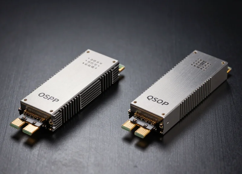
While QSFP-DD is dominant in current 400G deployments due to its backward compatibility with QSFP28, the OSFP (Octal Small Form Factor Pluggable) is increasingly viewed as the standard for 800G and 1.6T. The primary driver is thermal dissipation; OSFP modules feature integrated heat sinks and a larger surface area, allowing them to handle the 15W–25W power envelopes required by 800G and 1.6T DSPs. Organizations planning for 800G should consider OSFP-based 400G switches today to avoid a complete hardware refresh when the higher speeds become necessary.
| Feature | 400G (Standard) | 800G (Roadmap) | 1.6T (Future) |
|---|---|---|---|
| Electrical Lane Speed | 56G / 112G PAM4 | 112G PAM4 | 224G PAM4 |
| Preferred Form Factor | QSFP-DD / OSFP | OSFP / QSFP-DD800 | OSFP / OSFP-XD |
| Typical Module Power | 10W - 12W | 16W - 18W | 22W - 28W |
| Optical Connectors | LC, MPO-12, CS | MPO-16, SN, MDC | SN-MT, MDC, CPO |
Cabling Infrastructure and Connector Evolution
Legacy MPO-12 cabling is reaching its limit in high-density environments. The shift toward 800G favors MPO-16 for parallel optics (800G-DR8) and Very Small Form Factor (VSFF) connectors like SN and MDC. These connectors allow for individual breakout at the patch panel level without the need for bulky breakout cables, simplifying the management of 8x100G or 2x400G configurations. Investing in Single-Mode Fiber (SMF) with VSFF connectivity today provides the highest degree of investment protection for AI/ML fabrics.
- Can my 400G fiber plant support 800G?
Yes, if you have deployed high-quality Single-Mode Fiber (SMF). However, Multimode (MMF) reaches will be significantly restricted at 800G, likely requiring a transition to 100G-per-lane VCSELs or silicon photonics. - Why is thermal management the biggest hurdle?
As lane speeds increase, the Digital Signal Processor (DSP) within the transceiver consumes more power and generates more heat. Inadequate cooling at the switch port level can lead to signal degradation or hardware failure at 800G speeds. - Is 1.6T backward compatible with 400G?
Compatibility will depend on the SerDes version. While 1.6T OSFP-XD ports can technically support 400G modules with adapters, the electrical signaling (224G vs 56G) may require active conversion, increasing cost and latency.
Choosing between 100G and 400G is a pivotal moment for your infrastructure's lifecycle. While the leap requires careful planning, the benefits in power reduction and latency optimization are undeniable. Ready to optimize your data center? Contact our specialist team for a comprehensive TCO audit and migration roadmap.