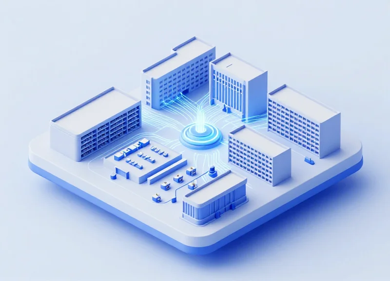
In an era of data-intensive research, cloud computing, and ubiquitous IoT, the traditional copper-based network is obsolete. Campus fiber connectivity represents the essential shift toward light-speed data transmission, providing the scalable, low-latency backbone required for modern institutional and corporate environments. This guide explores the technical intricacies and strategic implementation of high-performance optical networks.
The Evolution of Campus Networking: Why Fiber is Mandatory
The Shift from Copper to Glass: A Technological Imperative
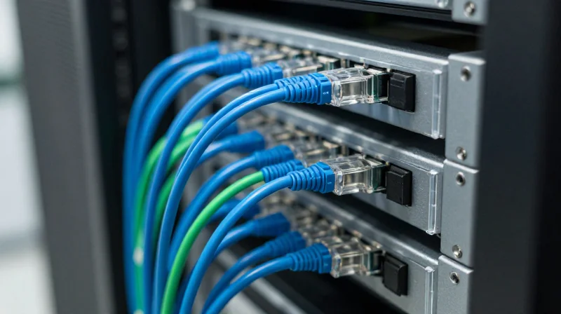
Campus fiber connectivity has transitioned from a specialized luxury to a fundamental requirement because the bandwidth demands of modern academic and corporate ecosystems have surpassed the physical capabilities of copper cabling. While twisted-pair copper was sufficient for megabit-scale communication, the shift toward multi-gigabit throughput, low-latency applications, and long-distance building interconnection requires the dielectric properties and massive bandwidth potential of optical fiber. Without a fiber-optic backbone, the contemporary campus faces insurmountable bottlenecks in data transmission, security, and scalability.
Overcoming the Physical Limits of Copper
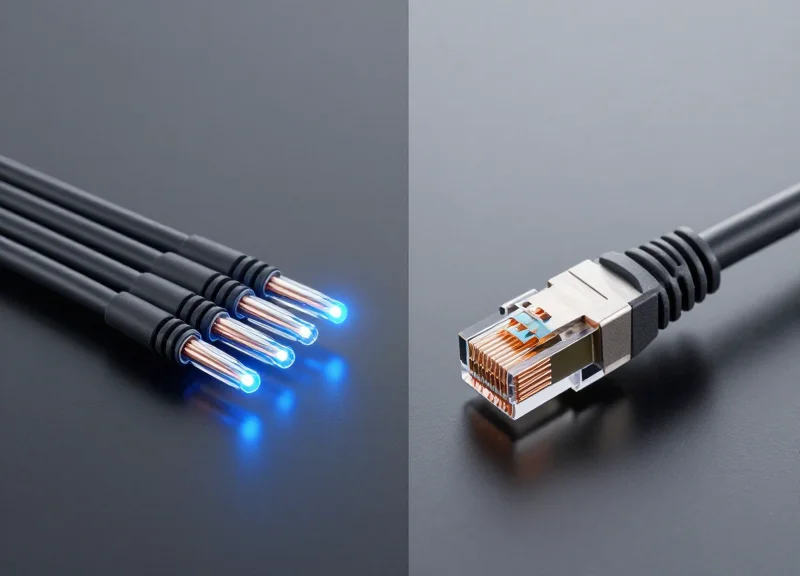
The primary catalyst for the fiber mandate is the '100-meter rule' inherent to copper-based Ethernet. Electrical signals traveling through copper suffer from significant attenuation and crosstalk as frequencies increase to support higher speeds. In a sprawling campus environment where buildings may be separated by hundreds or thousands of meters, copper is physically unable to maintain signal integrity at 10Gbps, 40Gbps, or 100Gbps. Fiber optics, utilizing light pulses, can sustain these speeds over many kilometers without the need for active repeaters, providing a seamless link across the entire campus geography.
| Feature | Copper (Cat6A/7) | Optical Fiber (SMF/MMF) |
|---|---|---|
| Max Distance @ 10Gbps | 100 Meters | 300m (MMF) to 40km (SMF) |
| Bandwidth Potential | Up to 10 Gbps | Up to 100+ Gbps per strand |
| EMI/RFI Immunity | Susceptible | Totally Immune |
| Weight and Size | Heavy and Bulky | Lightweight and Thin |
Immunity to Environmental Interference
Campuses often present challenging environments for data cabling, featuring high-voltage power lines, industrial machinery, and lightning risks. Copper cables act as antennas, picking up electromagnetic interference (EMI) and radio-frequency interference (RFI) that can corrupt data packets. Furthermore, copper links between buildings can create ground loops or attract lightning strikes, potentially damaging expensive networking hardware. Because fiber is made of glass or plastic (dielectric materials), it does not conduct electricity, making it immune to interference and providing a safer, more reliable connection between facilities.
- Why is fiber considered more future-proof than high-end copper?
Fiber capacity is largely determined by the optics at either end. Upgrading a fiber link from 10Gbps to 100Gbps often only requires swapping the transceivers, whereas copper has a hard physical ceiling that necessitates replacing the entire cable run. - Does the transition to Wi-Fi 7 make fiber less important?
Quite the opposite. High-speed wireless standards like Wi-Fi 6E and Wi-Fi 7 require multi-gigabit backhaul to the switch. Fiber is the only medium that can reliably feed these high-density access points without creating a bottleneck at the wired uplink. - What role does latency play in the mandate for campus fiber?
Fiber offers lower latency over distance compared to copper, which is critical for real-time applications like research computing, VoIP, and synchronized security systems across a large campus.
Understanding Single-Mode (SMF) and Multi-Mode (MMF) Fiber
Understanding Single-Mode (SMF) and Multi-Mode (MMF) Fiber
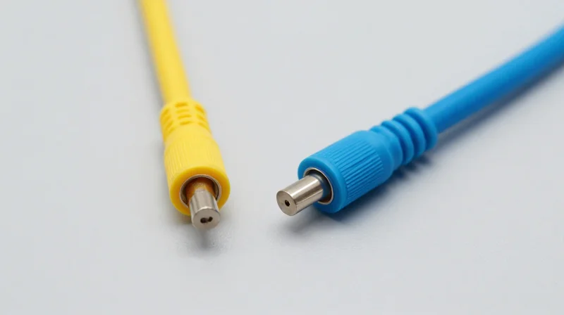
In a campus environment, the selection between Single-Mode Fiber (SMF) and Multi-Mode Fiber (MMF) is the most critical decision in physical layer design, as it dictates the maximum reachable distance, potential bandwidth, and the total cost of ownership for optical transceivers. While both types utilize high-purity glass to transmit data via light pulses, the primary technical difference lies in the core diameter and how light propagates through that core, which fundamentally alters their performance profiles for short-range versus long-haul applications.
Multi-Mode Fiber: The Short-Range Standard
Multi-mode fiber, categorized as OM3, OM4, and OM5, features a relatively large core diameter of 50 microns. This large core allows multiple "modes" or paths of light to travel through the cable simultaneously. Because the light reflects off the core walls at different angles, it is subject to modal dispersion over long distances, which limits its effective range. MMF typically employs Vertical-Cavity Surface-Emitting Lasers (VCSELs) operating at the 850nm wavelength. These light sources are significantly less expensive than the lasers required for SMF, making MMF the preferred choice for intra-building connections, server rooms, and horizontal cabling where distances rarely exceed 400 meters.
Single-Mode Fiber: The Long-Haul Backbone
Single-mode fiber (OS2) utilizes a much smaller core, approximately 9 microns in diameter. This narrow path forces light to travel in a single mode, effectively eliminating modal dispersion and allowing the signal to travel for kilometers with minimal attenuation. SMF requires precision laser light sources operating at 1310nm or 1550nm. While the fiber cable itself is often cheaper than MMF, the high-precision transceivers increase the initial hardware cost. In campus connectivity, OS2 is mandatory for inter-building backbones and connecting remote facilities that exceed the 500-meter limit of multi-mode standards.
| Fiber Category | Core Diameter | Light Source | Max Distance (10Gbps) | Application |
|---|---|---|---|---|
| OM3 | 50 microns | VCSEL (850nm) | 300 Meters | Legacy Building Backbones |
| OM4 | 50 microns | VCSEL (850nm) | 400 Meters | Standard High-Speed LAN |
| OM5 | 50 microns | VCSEL (850-953nm) | 440 Meters | SWDM / Future-proofing |
| OS2 | 9 microns | Laser (1310/1550nm) | Up to 40km | Inter-building/Campus Core |
- Can I use MMF and SMF together in the same link?
No. Due to the massive difference in core diameters (9 microns vs 50 microns), connecting them directly causes extreme signal loss. You must use a media converter or a switch with the appropriate SFP/SFP+ modules for each end. - Why is OM5 called 'Wideband' multi-mode?
OM5 is designed to support Shortwave Division Multiplexing (SWDM), allowing four different wavelengths to be sent over a single pair of fibers, effectively quadrupling capacity without adding more cables. - Is OS2 backward compatible with older OS1?
Yes, OS2 is essentially a lower-attenuation version of OS1. It is optimized for 1310nm and 1550nm wavelengths and is suitable for all campus-wide single-mode applications.
Network Topologies for Large-Scale Campus Deployment
Network Topologies for Large-Scale Campus Deployment
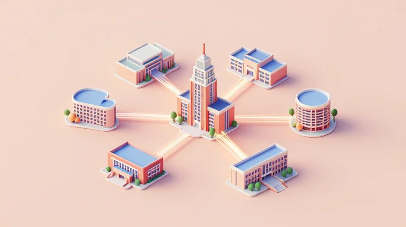
The physical and logical arrangement of fiber optic cables—known as network topology—serves as the foundational blueprint for a campus backbone, dictating how the network handles link failures, traffic congestion, and future building additions. Selecting the right topology requires balancing the upfront capital expenditure of fiber trenching against the operational necessity for high availability and low-latency throughput between distributed nodes.
The Star Topology: Centralized Management
In a Star (or Hub-and-Spoke) topology, all remote buildings or IDFs (Intermediate Distribution Frames) connect directly to a single centralized Core Data Center or MDF (Main Distribution Frame). This is the most common deployment for smaller campuses due to its simplicity in troubleshooting and centralized control. However, it presents a significant risk: the central hub is a single point of failure, and a cut in any individual 'spoke' cable will completely isolate that specific building from the network.
Ring Topology and Self-Healing Resilience
Ring topologies are frequently employed in campus backbones to provide cost-effective redundancy. By connecting buildings in a closed loop, data can travel in two directions. If a single fiber run is severed by construction or hardware failure, protocols like Ethernet Ring Protection Switching (ERPS) or Spanning Tree Protocol (STP) re-route traffic in the opposite direction. This 'self-healing' capability ensures that connectivity remains active for all nodes despite a single point of cable failure.
Mesh and Partial Mesh: Maximum Fault Tolerance
For mission-critical environments such as healthcare or research facilities, a Full Mesh or Partial Mesh topology is often the standard. In a full mesh, every building has a direct fiber connection to every other building, providing the highest possible redundancy and the shortest path for data transfer. While highly resilient, the sheer volume of fiber cabling and port density required makes it the most expensive option. Most large-scale campuses opt for a 'Partial Mesh,' where only the most critical core nodes are interconnected with multiple redundant paths.
| Topology | Redundancy Level | Cost Efficiency | Best Use Case |
|---|---|---|---|
| Star | Low (Single Point of Failure) | High (Minimal Cabling) | Small to Medium Schools/Offices |
| Ring | Medium (Resilient to one cut) | Moderate | Standard Campus Backbones |
| Partial Mesh | High (Multi-path options) | Low (High cable volume) | Mission-Critical / Large Universities |
Comparison of Topology Performance
- Which topology is most scalable for campus growth?
The Star topology is generally the easiest to scale because adding a new building only requires a single run back to the central hub, whereas a Ring requires breaking and extending the existing loop. - How does a Ring topology impact latency?
In a large Ring, data may have to pass through multiple intermediate switches to reach its destination, slightly increasing latency compared to a direct Star connection. - Is fiber consumption higher in Mesh networks?
Yes, Mesh networks require significantly more fiber strands and higher-density patch panels, leading to much higher material and labor costs during the trenching and installation phase.
Optical Loss Budgets and Signal Integrity
Optical Loss Budgets and Signal Integrity
An optical loss budget is the calculated maximum amount of power loss a fiber link can sustain before it fails to meet the receiver's sensitivity requirements. In a campus environment, maintaining signal integrity requires rigorous accounting of every decibel (dB) lost to fiber attenuation, connector interfaces, and fusion splices. If the total cumulative loss exceeds the 'link power budget' of the transceiver (the difference between the transmitter's output power and the receiver's minimum sensitivity), the link will experience high Bit Error Rates (BER) or total connectivity failure.
Key Components of Optical Attenuation
Signal degradation is primarily driven by three factors: inherent fiber attenuation, connector insertion loss, and splice loss. Fiber attenuation is wavelength-dependent and measured in dB per kilometer. Connectors contribute loss through slight misalignments or air gaps, while splices—though more efficient than connectors—introduce minor discontinuities in the glass core.
| Component Type | Typical Loss (Single-Mode) | Typical Loss (Multi-Mode) | TIA-568 Standard Max |
|---|---|---|---|
| Fiber Attenuation (per km) | 0.4 dB @ 1310nm | 3.5 dB @ 850nm | Variable by wave |
| Mated Connector Pair | 0.2 dB to 0.5 dB | 0.3 dB to 0.5 dB | 0.75 dB |
| Fusion Splice | 0.05 dB | 0.05 dB | 0.3 dB |
| Safety Margin | 2.0 dB to 3.0 dB | 2.0 dB to 3.0 dB | N/A |
Calculating the Link Budget
To calculate the total loss for a campus run, engineers use a predictive formula. This calculation is essential during the design phase to determine if mid-span amplification or specific high-power transceivers are necessary.
Total_Loss = (Fiber_Length * Attenuation_Rate) + (Number_of_Connectors * Connector_Loss) + (Number_of_Splices * Splice_Loss) + Safety_MarginSignal Integrity and Dispersion
While attenuation reduces signal strength, dispersion affects the signal's clarity. In campus MMF, modal dispersion—where different light paths arrive at different times—limits bandwidth over distance. In SMF, chromatic dispersion occurs because different wavelengths of light travel at slightly different speeds. At speeds of 100Gbps and above, even a well-budgeted link can fail if dispersion causes 'pulse smearing,' where bits overlap and become indistinguishable to the receiver.
- Why is a safety margin necessary?
A safety margin (typically 2-3 dB) accounts for component aging, environmental temperature fluctuations, and potential future repairs, such as emergency splices if a cable is cut. - How does connector cleanliness affect the budget?
Dirty connectors are the leading cause of failed loss budgets. A single speck of dust can increase connector loss from 0.2 dB to 5.0 dB or more, effectively killing the link. - What is 'Passive Optical Loss'?
It refers to the total loss accumulated through all non-powered components between the transmitter and receiver, including patch cords, panels, and the permanent link.
Inside vs. Outside Plant (ISP vs. OSP) Fiber Specifications
Distinguishing ISP and OSP Fiber Specifications
Campus fiber connectivity relies on a bifurcated approach to cable engineering, where Inside Plant (ISP) fiber prioritizes fire safety and flexibility for indoor routing, while Outside Plant (OSP) fiber focuses on environmental resilience and mechanical strength to withstand burial, moisture, and temperature fluctuations. Selecting the wrong cable type not only risks signal degradation but can also violate local building codes or lead to catastrophic physical failure of the link due to environmental stressors like water ingress or rodent damage.
Outside Plant (OSP) Fiber: Environmental Fortress
OSP fiber is designed for the harsh reality of the exterior world. Whether deployed in underground ducts, direct-buried, or strung aerially between campus buildings, these cables must resist water ingress using gel-filled buffer tubes or dry water-blocking tapes. To prevent damage from rodents and physical crushing, OSP cables often feature corrugated steel tape armor or thick polyethylene (PE) jackets. However, because PE jackets are highly flammable and produce toxic smoke, the National Electrical Code (NEC) typically limits their run to 50 feet inside a building before they must transition to an ISP-rated cable.
Inside Plant (ISP) Fiber: Safety and Fire Compliance
Within campus structures, the engineering priority shifts from environmental protection to human safety and fire mitigation. ISP fiber utilizes flame-retardant jackets, most commonly categorized as Plenum (OFNP) or Riser (OFNR). Plenum cables are mandatory in air-handling spaces because they are treated with specialized materials that emit low smoke and resist flame spread. Riser cables are intended for vertical shafts connecting floors. Unlike OSP cables, ISP versions are more flexible and lack heavy armoring, making them easier to manage within tight cable trays and conduits.
| Feature | Outside Plant (OSP) | Inside Plant (ISP) |
|---|---|---|
| Primary Jacket | Polyethylene (PE) | PVC or Low Smoke Zero Halogen (LSZH) |
| Safety Rating | Unrated (Flammable) | Plenum (OFNP) or Riser (OFNR) |
| Water Protection | Gel-filled or Dry-block | None (Indoor environment) |
| Mechanical | Armored (Steel Tape) | Unarmored or Interlocking Armor |
| Typical Use | Inter-building (Ducts/Burial) | Intra-building (Horizontal/Vertical) |
Physical Cable Selection FAQ
- Can I use OSP cable for the entire campus run?
No. Due to fire safety regulations (NEC/NFPA 70), OSP cable can only extend 50 feet inside a building from the point of entry unless it is enclosed in a continuous grounded metal conduit. - What is Indoor/Outdoor (I/O) rated fiber?
I/O fiber is a hybrid solution that features a flame-retardant jacket for indoor compliance and UV/moisture protection for outdoor use, eliminating the need for a transition splice at the building entrance. - When is 'Interlocking Armor' used in ISP fiber?
Interlocking armor (usually aluminum) is used in ISP environments where high physical protection is needed without the use of a separate conduit, such as in busy data centers or industrial campus zones.
The Role of Transceivers and Active Equipment
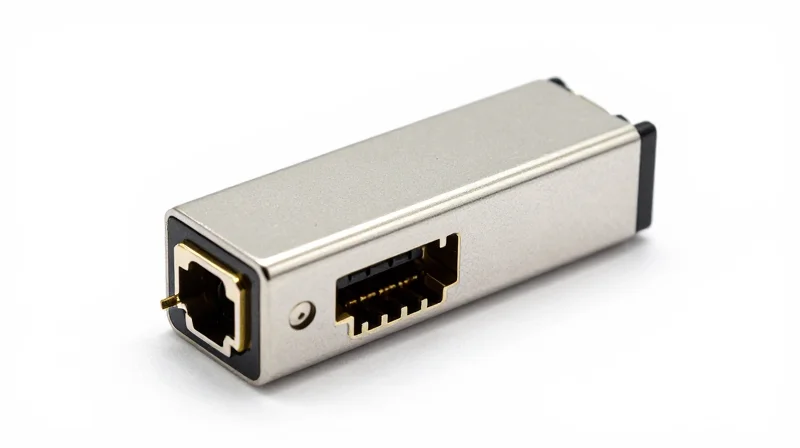
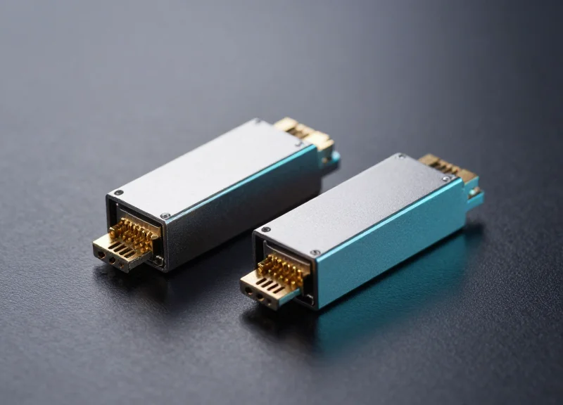
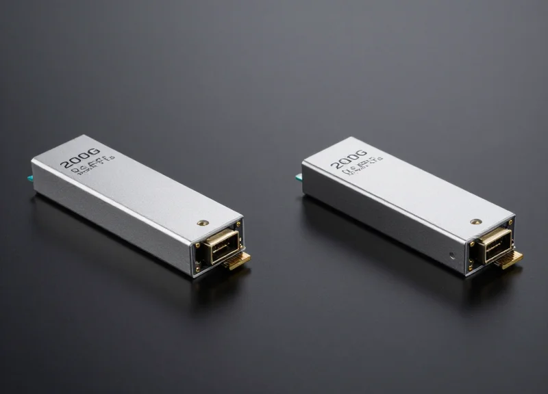
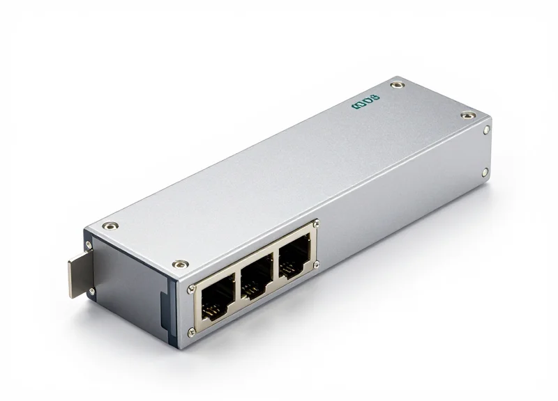
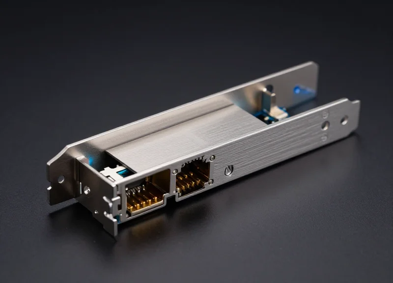
Transceivers and active equipment serve as the critical conversion layer in campus fiber connectivity, transforming electronic data from switches into optical light pulses for long-distance transmission. While the fiber optic cable provides the medium, the active electronics—specifically the Small Form-factor Pluggable (SFP) modules and the switch ports they inhabit—determine the maximum throughput, reach, and wavelength of the link. Without the precise synchronization between the transceiver's laser and the switch's processing power, the high bandwidth potential of glass fiber remains inaccessible.
The Evolution of Transceiver Form Factors
Modern campus networks rely on a variety of standardized form factors to scale from the edge to the core. The transition from 10G to 100G has seen the adoption of denser, more thermally efficient modules. These modules utilize Multi-Source Agreements (MSAs) to ensure interoperability between different hardware vendors, allowing a Cisco switch to communicate with a Juniper switch via standardized optics.
| Module Type | Max Data Rate | Primary Application | Fiber Type |
|---|---|---|---|
| SFP+ | 10 Gbps | Access layer to distribution | MMF (SR) / SMF (LR) |
| QSFP+ | 40 Gbps | Distribution to core uplinks | MMF (SR4) / SMF (LR4) |
| QSFP28 | 100 Gbps | High-density core & data center | MMF (SR4) / SMF (LR4/PSM4) |
| SFP28 | 25 Gbps | High-speed server/storage links | MMF / SMF |
Matching Optics to Fiber Infrastructure
Selecting the correct transceiver requires aligning the optical wavelength with the physical fiber plant installed. For short-range (SR) applications, transceivers typically use 850nm lasers over Multi-Mode Fiber (MMF). For campus backbones spanning several kilometers, Long-Reach (LR) or Extended-Reach (ER) modules use 1310nm or 1550nm wavelengths over Single-Mode Fiber (SMF) to minimize signal attenuation and dispersion.
Active Equipment Integration and Power Management
As port densities increase, active equipment faces challenges regarding power consumption and heat dissipation. A switch populated with forty-eight 100G QSFP28 modules generates significant thermal output. Network engineers must account for the power budget of the chassis and the cooling capacity of the MDF/IDF room to prevent 'thermal throttling,' which can degrade optical performance and increase bit error rates (BER).
- Can I use a 10G SFP+ module in a 25G SFP28 port?
Generally, yes. SFP28 ports are often backwards compatible with SFP+ modules, though the port must be manually configured to the lower speed in the switch operating system. - What is the difference between SR and LR transceivers?
SR (Short Reach) is designed for multi-mode fiber and typically covers distances up to 400m, while LR (Long Reach) is designed for single-mode fiber and can reach up to 10km. - Why is 'DOM' or 'DDM' important for transceivers?
Digital Optical Monitoring (DOM) allows network administrators to monitor real-time parameters such as optical output power, input power, temperature, and laser bias current.
Passive Optical Networks (PON) in Campus Environments
Passive Optical Network (PON) technology, originally developed for Fiber-to-the-Home (FTTH) applications, is increasingly being adopted in campus environments to create Optical LANs (OLAN). Unlike traditional Active Ethernet, which requires powered switches at frequent intervals, PON uses unpowered optical splitters to distribute signals from a central Optical Line Terminal (OLT) to multiple Optical Network Terminals (ONTs) at the edge. This transition significantly reduces the footprint of telecommunications closets and simplifies the overall cabling architecture by utilizing a point-to-multipoint topology.
The Shift from Active Ethernet to Passive Architecture
The core advantage of PON lies in its ability to serve multiple endpoints through a single fiber strand. In a traditional campus network, every workstation or access point requires a dedicated fiber pair or copper run back to an active switch. In contrast, a single fiber from the core can be split into 32 or 64 connections using passive glass prisms. This reduces the total volume of fiber required in the backbone and eliminates the need for power, cooling, and UPS systems in mid-span distribution rooms, often referred to as 'collapsed' backbone architecture.
| Feature | Active Ethernet | GPON | XGS-PON |
|---|---|---|---|
| Mid-span Equipment | Active Switches | Passive Splitters | Passive Splitters |
| Downstream Bandwidth | 1G to 100G (Dedicated) | 2.5 Gbps (Shared) | 10 Gbps (Shared) |
| Upstream Bandwidth | 1G to 100G (Dedicated) | 1.25 Gbps (Shared) | 10 Gbps (Shared) |
| Max Reach | 10km+ (Fiber-based) | 20 km | 20 km |
| Power Consumption | High (requires cooling) | Very Low (no mid-span power) | Very Low (no mid-span power) |
XGS-PON: Future-Proofing Campus Bandwidth
While GPON has been the standard for several years, XGS-PON is the current gold standard for campus upgrades. It provides 10 Gbps symmetrical bandwidth, meaning both upload and download speeds are equal. This is critical for modern campus environments that must handle high-density Wi-Fi 6 or Wi-Fi 7 access points, large-scale video conferencing, and massive cloud-based research data transfers. XGS-PON can often coexist on the same fiber plant as GPON through Wavelength Division Multiplexing (WDM), allowing for a phased migration.
- Is PON more secure than traditional Ethernet?
Because PON is a shared medium at the physical layer, it utilizes AES-128 or AES-256 encryption at the hardware level for all downstream traffic, ensuring that an ONT can only decrypt data intended for its specific user, providing security comparable to or better than traditional switched networks. - How does PON affect the 'Green' rating of a building?
PON significantly contributes to LEED certifications and green initiatives by reducing energy consumption by up to 30 to 60 percent. It eliminates the need for thousands of pounds of copper cabling and reduces the requirement for air-conditioned telecommunications rooms. - What are the distance limitations of Campus PON?
Unlike copper-based Ethernet which is limited to 100 meters, PON can maintain signal integrity for up to 20 kilometers without any active regeneration, making it ideal for sprawling university or corporate campuses.
Future-Proofing: Preparing for 400G and Beyond
The Roadmap to 400G and Terabit Ethernet
Future-proofing campus fiber connectivity requires a transition from legacy multi-mode infrastructure to high-density single-mode fiber (SMF) solutions capable of supporting 400GbE and future 800GbE or 1.6TbE standards. By prioritizing high-strand count cables and modular optical distribution frames (ODFs), organizations can leverage Wave Division Multiplexing (WDM) and parallel optics to scale bandwidth exponentially while avoiding the prohibitive costs of additional civil works or new cable pulls.
High-Strand Count and Ribbon Fiber Deployment
To accommodate the density required for 400G, campus backbones should move away from traditional 12- or 24-strand increments. Modern deployments frequently utilize high-strand count cables ranging from 144 to 864 strands. Ribbon fiber is particularly effective in these scenarios, as it allows for mass-fusion splicing, significantly reducing installation time and providing a smaller footprint within congested underground ducts. This 'over-provisioning' strategy ensures that as network demand grows, the physical pathing is already in place.
| Infrastructure Level | Legacy Strand Count | Future-Proof Recommendation | Typical Application |
|---|---|---|---|
| Intra-Building (Riser) | 12-24 Strands | 48-144 Strands | High-bandwidth departmental uplinks |
| Inter-Building (Backbone) | 48-96 Strands | 288-864 Strands | Core-to-Distribution links |
| Data Center Interconnect (DCI) | 144 Strands | 1728+ Strands | Cloud and high-performance computing |
Modular Infrastructure: The Role of MPO/MTP and Ultra-High Density Patching
Modular patching systems, such as MPO/MTP-based cassettes, are essential for seamless upgrades. Instead of replacing the entire cable plant, administrators can swap LC cassettes for MPO adapters when moving from 10G/40G to 400G. This 'plug-and-play' approach minimizes downtime and allows for the incremental rollout of high-speed ports. Utilizing Ultra-High Density (UHD) panels allows for more terminations per rack unit (RU), preserving valuable floor space in campus data centers and MDF rooms.
- Why is OS2 Single-Mode Fiber preferred for future-proofing?
Unlike Multi-mode fiber, OS2 has virtually unlimited bandwidth capacity and much lower attenuation, making it the only medium capable of supporting 400G, 800G, and future Terabit standards over campus-scale distances. - What is the benefit of Ribbon Fiber in campus environments?
Ribbon fiber allows for 12 fibers to be spliced simultaneously, which drastically lowers labor costs during large-scale deployments and maximizes space efficiency in existing conduit and duct systems. - How do modular panels reduce Total Cost of Ownership (TCO)?
Modular panels allow for the repurposing of existing fiber trunks; users only need to update the interface modules to change connectors or speeds, avoiding expensive site surveys and cable installation.
Testing and Certification Standards
Testing and Certification Standards
Fiber optic certification is the definitive process of verifying that a campus cabling installation performs within the specific optical loss budgets and physical parameters defined by industry standards such as TIA-568 and ISO/IEC 11801. Unlike simple continuity testing, formal certification uses calibrated equipment to prove that the infrastructure can support high-speed applications like 100G Ethernet, providing a 'birth certificate' for the network that is often required for manufacturer warranties.
Tier 1 vs. Tier 2 Testing Methodologies
Industry standards define two levels of testing. Tier 1 is the mandatory baseline for all fiber installations, focusing on total link loss and length. Tier 2 is an optional but highly recommended supplemental test that provides a visual characterization of the fiber link to identify specific points of failure or degradation.
| Feature | Tier 1 (OLTS) | Tier 2 (OTDR) |
|---|---|---|
| Primary Tool | Optical Loss Test Set (OLTS) | Optical Time Domain Reflectometer (OTDR) |
| Measurements | Total Attenuation (Loss), Length, Polarity | Splice Loss, Connector Loss, Reflectance, Total Loss |
| Pass/Fail Criteria | Based on Link Loss Budget | Based on Individual Component Performance |
| Best Use Case | Basic Certification and Compliance | Troubleshooting and High-Precision Characterization |
Adhering to TIA/EIA and ISO Standards
Compliance is primarily governed by the ANSI/TIA-568.3-D standard in North America and ISO/IEC 14763-3 internationally. These standards specify the 'Encircled Flux' (EF) launch conditions for multimode fiber, which reduces measurement uncertainty by controlling how light enters the fiber during testing. Failure to use EF-compliant launch cords often results in optimistic loss readings, potentially masking underlying installation issues.
- What is a Link Loss Budget?
It is the maximum amount of signal power loss (measured in dB) that a fiber link can tolerate while still allowing the connected hardware to function reliably. - Why is OTDR testing necessary if OLTS passes?
An OLTS might show a 'Pass' for total loss, but an OTDR can reveal a single high-loss connector or a stressed bend that could cause intermittent errors or future failures. - What is 'Reference Setting' in fiber testing?
Referencing is the process of 'zeroing out' the test leads to ensure the reported loss values only reflect the cabling under test, not the equipment patches.
Campus fiber connectivity is the bedrock of digital transformation for any large-scale facility. By prioritizing high-quality optical specifications and resilient topology designs, organizations can build a network that serves them for decades. Ready to upgrade your infrastructure? Consult with our senior network engineers to design a custom fiber solution today.