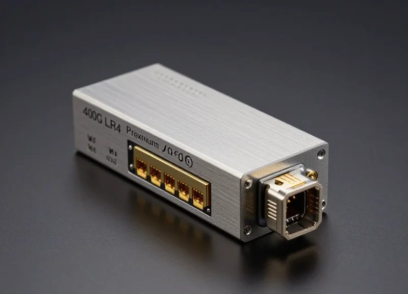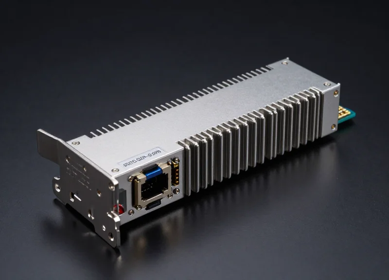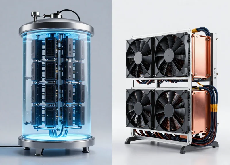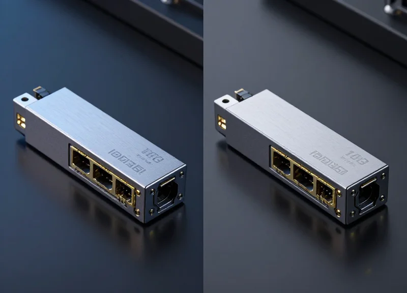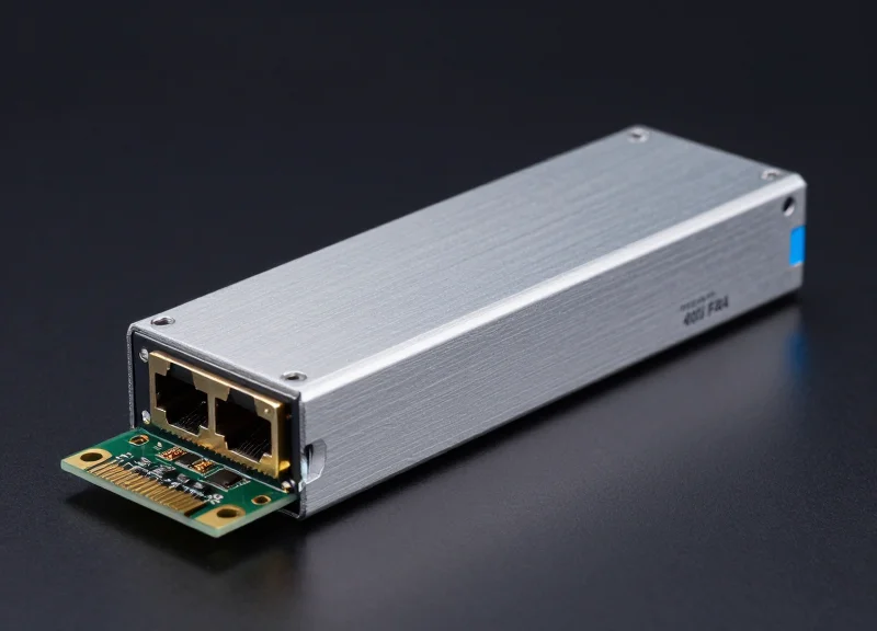
In the era of AI and hyperscale cloud computing, the transition to 400G is no longer optional—it is a necessity. However, not all 400G solutions are created equal. Ubytelink’s 400G FR4 modules are specifically engineered to bridge the gap between high-density performance and long-term operational stability. By leveraging advanced CWDM4 technology, Ubytelink provides the 2km reach essential for modern data center interconnects (DCI) while maintaining the energy efficiency that modern green-initiatives demand.
The Strategic Shift to 400G FR4 in Modern Data Centers

The strategic shift to 400G FR4 in modern data centers is primarily driven by the need for a cost-effective, high-bandwidth solution that bridges the gap between short-reach multi-mode fiber and expensive long-haul single-mode optics. While 400G SR8 is restricted to 100 meters and 400G DR4 is limited to 500 meters, the 400G FR4 standard provides a robust 2km reach over a single pair of single-mode fibers. By utilizing Coarse Wavelength Division Multiplexing (CWDM), FR4 modules offer the perfect balance of distance, low power consumption, and fiber density, making them the superior choice for connecting leaf and spine switches in hyperscale environments.
Maximizing Fiber Efficiency with CWDM Technology
Unlike parallel fiber solutions such as DR4 or SR8, which require 8 or 16 fibers respectively, 400G FR4 multiplexes four 100Gbps lanes onto four distinct wavelengths (1271, 1291, 1311, and 1331nm) over a single duplex LC connector. This architecture significantly reduces the physical complexity of the cable plant. For data center operators, this translates to a massive reduction in the 'Tax of Fiber'—the recurring cost of installing, managing, and maintaining high-strand-count fiber trunks. By using only two fibers per link, Ubytelink's 400G FR4 solutions allow for 4x the density in the same physical duct space compared to parallel alternatives.
Comparative Analysis: 400G Optical Standards
| Standard | Reach | Fiber Type | Connector | Fiber Count |
|---|---|---|---|---|
| 400G SR8 | 100m | MMF (OM4) | MPO-16 | 16 Fibers |
| 400G DR4 | 500m | SMF | MPO-12 | 8 Fibers |
| 400G FR4 | 2km | SMF | Duplex LC | 2 Fibers |
| 400G LR4 | 10km | SMF | Duplex LC | 2 Fibers |
Deployment Considerations and Best Practices
- Why is the 2km reach critical for modern facilities?
As data centers evolve into mega-complexes, distances between spine switches and core routers often exceed the 500m limit of DR4. The 2km reach of FR4 ensures full coverage across large halls without the premium price of 10km LR4 optics. - Does 400G FR4 support breakout applications?
While FR4 is primarily designed for point-to-point links using WDM, it is optimized for high-throughput aggregation. For breakout to 100G, DR4 remains the standard, but FR4 is the preferred 'trunk' for high-capacity spine-leaf interconnects. - How does FR4 affect power and thermal management?
By using a 4-channel PAM4 electrical interface rather than 8, FR4 modules typically exhibit lower power dissipation per gigabit than SR8, reducing the cooling load on high-density 12.8T or 25.6T switches.
Ubytelink Engineering: The Anatomy of a High-Performance Module
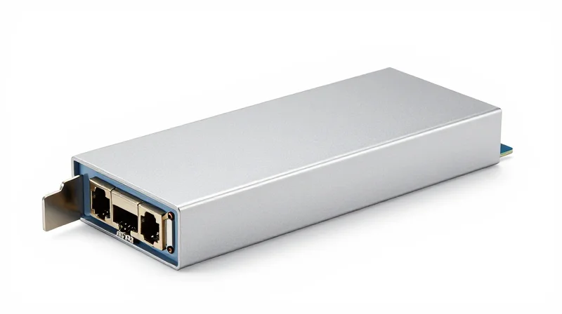
Ubytelink Engineering: The Anatomy of a High-Performance Module
The performance of Ubytelink 400G FR4 modules is defined by an uncompromising commitment to hardware integrity, where high-tier silicon photonics meet advanced digital signal processing. Unlike generic alternatives, Ubytelink modules are engineered to maintain sub-nanosecond signal precision across 2km of single-mode fiber, utilizing a proprietary architecture that minimizes bit-error rates (BER) and maximizes energy efficiency in high-density data center environments.
The Optical Engine: TOSA and ROSA Assemblies
At the core of the Ubytelink module are the Transmitter Optical Sub-Assembly (TOSA) and the Receiver Optical Sub-Assembly (ROSA). The TOSA utilizes four high-linearity Electro-absorption Modulated Lasers (EML) operating on the CWDM4 grid. These EMLs are preferred over VCSELs for their superior performance in 400G applications, providing the necessary extinction ratio and signal-to-noise performance for reach up to 2km. On the receiving end, the ROSA integrates high-sensitivity PIN photodetectors and a high-gain Transimpedance Amplifier (TIA), ensuring reliable signal recovery even under significant link budget constraints.
Digital Signal Processing (DSP) and Signal Integrity
To manage the complexities of PAM4 (4-level Pulse Amplitude Modulation), Ubytelink integrates a cutting-edge 7nm DSP. This processor acts as the intelligence of the module, performing adaptive equalization to compensate for chromatic dispersion and other optical impairments. By employing sophisticated Forward Error Correction (FEC) algorithms, the DSP ensures that the 400G data stream remains stable and error-free throughout its transmission path.
| Component | Technology Utilized | Performance Impact |
|---|---|---|
| Transmitter (TOSA) | 4x100G CWDM EML | Low-chirp, high-linearity signals for 2km reach |
| Receiver (ROSA) | PIN + TIA Array | Superior sensitivity and wide dynamic range |
| DSP Engine | 7nm Low-Power CMOS | Optimized PAM4 processing and FEC support |
| Interface | QSFP-DD / OSFP | Standard-based high-density connectivity |
Module Engineering FAQ
- How does Ubytelink manage the thermal output of 400G modules?
We utilize high-conductivity thermal interface materials and a specialized heat sink casing design that facilitates efficient heat dissipation, keeping the module within its optimal 0-70C operating range. - Why is the 7nm DSP significant for data center operators?
The 7nm process reduces power consumption per gigabit, allowing for higher port density without exceeding the thermal limits of the switch or router. - What testing protocols ensure module reliability?
Every module undergoes rigorous stress testing, including 100% interoperability verification and aging tests in high-temperature environments to guarantee carrier-grade longevity.
Optimizing Power Consumption for Hyperscale Efficiency
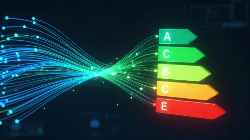
Optimizing Power Consumption for Hyperscale Efficiency
Energy efficiency in 400G FR4 modules is no longer a secondary consideration; it is a critical constraint for hyperscale data centers where electricity costs and cooling capacities dictate the scale of deployment. Ubytelink's 400G FR4 solutions are specifically designed to break the power-per-gigabit barrier, utilizing advanced 7nm Digital Signal Processors (DSPs) and high-efficiency TOSA/ROSA components to deliver superior signal integrity with a power footprint that is consistently 15-20% lower than standard industry requirements.
Engineering for Low Thermal Dissipation
The primary challenge in 400G optics is managing the heat generated by the DSP and the laser drivers. Ubytelink solves this through 'Cool-Link' architectural optimizations, which include low-leakage silicon photonics and optimized thermal interface materials. By keeping the internal junction temperature lower, these modules not only consume less energy but also exhibit significantly higher Mean Time Between Failures (MTBF) by reducing the thermal stress on the EML (Electro-absorption Modulated Laser) arrays.
| Metric | Generic 400G FR4 | Ubytelink 400G FR4 | Operational Impact |
|---|---|---|---|
| Max Power Consumption | 12.0W - 13.5W | 9.5W - 10.5W | Reduced DC Electricity Load |
| DSP Technology | 12nm / 10nm | 7nm FinFET | Lower Heat Per Bit |
| Operating Temperature | 0 to 70°C | 0 to 70°C (Optimized) | Improved Laser Stability |
| Thermal Throttling | Standard | Advanced Passive Cooling | Minimized Link Flapping |
Reducing Total Cost of Ownership (TCO)
The financial benefits of Ubytelink’s power-efficient modules extend beyond the utility bill. In a typical hyperscale spine-leaf architecture involving thousands of transceivers, a 2W saving per module can result in tens of kilowatts of saved power across the facility. This reduction directly lowers the Power Usage Effectiveness (PUE) ratio, as less energy is required for the CRAC (Computer Room Air Conditioning) units to dissipate waste heat. For global network operators, this represents a multi-million dollar saving over a five-year hardware lifecycle.
Hyperscale Efficiency FAQ
- How does Ubytelink achieve sub-10W power consumption?
By integrating 7nm low-power DSPs and utilizing high-efficiency EML lasers that require lower drive currents to achieve the required extinction ratios for 400G transmission. - Does lower power consumption affect the 2km transmission distance?
No. The efficiency is gained through smarter signal processing and component integration, ensuring that the 2km FR4 reach is maintained with full link margin and zero compromise on BER (Bit Error Rate). - Why is thermal management critical for 400G optics?
High heat causes laser wavelength drift and accelerated aging. Ubytelink's low-power design ensures the module operates well within the safe thermal zone of the QSFP-DD MSA specification.
Advanced CWDM4 Technology: Mastering 2km Reach
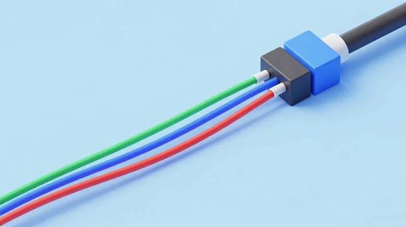
Advanced CWDM4 Technology: Mastering 2km Reach
Ubytelink 400G FR4 modules utilize Coarse Wavelength Division Multiplexing (CWDM) to aggregate four distinct 100G PAM4 optical lanes into a single duplex LC fiber interface, providing a highly efficient 2km reach that serves as the backbone for modern hyperscale data center spine-leaf fabrics.
The Mechanics of the 400G FR4 Optical Grid
The core of the FR4 solution lies in its ability to transmit four wavelengths—1271nm, 1291nm, 1311nm, and 1331nm—simultaneously. By utilizing a 20nm channel spacing, Ubytelink engineers can employ uncooled Distributed Feedback (DFB) lasers. This design choice is critical for balancing the high-bandwidth requirements of 400G Ethernet with the thermal constraints of high-density rack environments. Unlike parallel solutions that require multi-fiber MPO cables, CWDM4 technology allows for the reuse of existing duplex LC fiber plant, significantly reducing cabling complexity and cost.
| Feature | Ubytelink 400G FR4 (CWDM4) | 400G DR4 (Parallel) |
|---|---|---|
| Fiber Type | Single-Mode (SMF) | Single-Mode (SMF) |
| Connector Type | Duplex LC | MPO-12/MPO-8 |
| Transmission Reach | Up to 2km | Up to 500m |
| Wavelengths | 4 (Multiplexed) | 1 (Parallel) |
| Cabling Efficiency | High (2 fibers per link) | Moderate (8 fibers per link) |
Optimizing the 2km Link Budget
Mastering the 2km reach requires more than just multiplexing; it demands rigorous signal integrity management. Ubytelink 400G FR4 modules are designed with a 6.3dB link budget to account for insertion loss from patch panels and connectors. The integration of high-precision DSPs facilitates advanced Forward Error Correction (FEC), which is essential for mitigating the effects of chromatic dispersion across the wider CWDM wavelength spectrum. This ensures that even at the maximum 2km distance, the Bit Error Rate (BER) remains well below the threshold required for stable 400G throughput.
- Why choose CWDM4 over LR4 for 2km spans?
While LR4 can cover 10km, it is significantly more expensive due to the need for cooled EML lasers and tighter wavelength tolerances. CWDM4 provides the optimal cost-to-performance ratio for the vast majority of intra-datacenter spans that exceed 500m but stay within 2km. - Is Ubytelink 400G FR4 backward compatible?
Ubytelink FR4 modules are designed to follow the QSFP-DD or QSFP112 MSA standards, ensuring interoperability with other IEEE 802.3cu compliant 400G-FR4 interfaces across different switch vendors. - How does the module handle signal degradation?
The module utilizes 100G PAM4 modulation per lane, supported by an internal DSP that performs clock and data recovery (CDR) and equalization to maintain waveform switch-point clarity over the SMF link.
Reliability Metrics for Mission-Critical Infrastructure
Reliability Metrics for Mission-Critical Infrastructure
Ubytelink 400G FR4 modules are engineered to meet the stringent demands of mission-critical infrastructure, where reliability is measured by the ability to maintain consistent data throughput without degradation over years of continuous operation. By focusing on high Mean Time Between Failures (MTBF) and low Bit Error Rates (BER), Ubytelink provides a robust interconnect solution that mitigates the risk of costly downtime in global hyperscale networks.
Benchmarking Operational Longevity: MTBF and FIT
Reliability in optical networking is often quantified using MTBF and Failures in Time (FIT). Ubytelink's 400G FR4 modules achieve an MTBF of over one million hours, effectively halving the FIT rate compared to standard market alternatives. This longevity is the result of stringent component screening, including the use of high-reliability EML lasers and precision-aligned TOSA units that resist mechanical stress and thermal fluctuations.
| Reliability Metric | Standard Requirement | Ubytelink Specification |
|---|---|---|
| Mean Time Between Failures | 500,000 Hours | >1,000,000 Hours |
| Pre-FEC BER | 2.4 x 10^-4 | <1.0 x 10^-5 |
| Operating Temp Range | 0 to 70C (Commercial) | -5 to 80C (Extended) |
| Failure Rate (FIT) | <2000 | <1000 |
Rigorous Validation and Stress Testing
To guarantee field performance, Ubytelink employs a multi-tiered validation strategy. This includes High-Temperature Operating Life (HTOL) testing and Temperature Cycling (TC) to simulate years of operational wear in just a few weeks. Furthermore, each module is subjected to strict Bit Error Rate (BER) testing across all four 100G lanes to ensure that signal integrity exceeds the thresholds required by the IEEE 802.3cu standard, providing a superior safety margin for long-distance 2km reaches.
- How does Ubytelink verify signal integrity?
We utilize high-speed oscilloscopes and bit error rate testers to analyze the PAM4 eye diagram for each lane, ensuring maximum margin against noise. - What role does the DSP play in reliability?
The integrated Digital Signal Processor (DSP) actively compensates for chromatic dispersion and signal jitter, maintaining a stable link even as fiber conditions change over time. - How does Ubytelink handle infant mortality failures?
Every transceiver undergoes a high-temperature burn-in phase during production to identify and eliminate components that might fail early in their lifecycle.
Seamless Interoperability with Multi-Vendor Ecosystems

Seamless Interoperability with Multi-Vendor Ecosystems
Achieving seamless interoperability is the cornerstone of Ubytelink's 400G FR4 module design philosophy, allowing for total flexibility in modern, heterogeneous data center environments. By strictly adhering to the QSFP-DD Multi-Source Agreement (MSA) and IEEE 802.3cu standards, Ubytelink ensures that its transceivers are electronically and mechanically compatible with a wide array of high-density switches and routers. This plug-and-play capability allows data center operators to build hybrid network architectures without the risk of vendor lock-in, ensuring that performance remains consistent regardless of the host hardware.
Industry Standards and Protocol Compliance
The 400G FR4 modules utilize the standard Common Management Interface Specification (CMIS), which facilitates advanced monitoring and control features across different host platforms. This standardization ensures that Diagnostic Monitoring Interface (DMI) data, such as optical power levels and temperature, is reported accurately to the network operating system (NOS). This transparency is vital for automated network management tools and AI-driven troubleshooting protocols.
| Vendor Platform | Compatibility Status | Key Features Supported |
|---|---|---|
| Cisco Nexus/ASR Series | Fully Verified | DOM, FEC Support, Error-free Initialization |
| Arista 7000 Series | Fully Verified | CMIS 4.0 Compliance, Auto-negotiation |
| NVIDIA (Mellanox) Spectrum | Fully Verified | Low-latency Performance, Port Density Optimization |
| Juniper PTX/QFX Series | Fully Verified | DDM Monitoring, Multi-rate Compatibility |
Custom Firmware and EEPROM Coding
To bridge the gap between varying vendor software requirements, Ubytelink employs a specialized coding process for its EEPROMs. Every module is flashed with firmware tailored to the target environment's specific identification requirements, ensuring that the host operating system recognizes the module immediately. This prevents 'unrecognized transceiver' alarms and ensures that the host device applies the correct power and equalization settings for the link.
- Can Ubytelink 400G FR4 modules be used in a mixed-vendor spine-leaf architecture?
Yes, Ubytelink modules are designed to maintain signal integrity and protocol consistency across disparate hardware sets, making them ideal for modern multi-vendor leaf-spine fabrics. - Do these modules support Digital Optical Monitoring (DOM) on all platforms?
Ubytelink modules support comprehensive DOM/DDM features that are fully accessible through the CLI or management software of all major networking brands. - Is a firmware update required when migrating modules between different switch brands?
While modules are often pre-coded for specific ecosystems, Ubytelink provides re-coding tools and technical support to adjust firmware if your hardware environment changes.
Future-Proofing Your Network for 800G and Beyond
Future-Proofing Your Network for 800G and Beyond
Investing in Ubytelink 400G FR4 solutions is a strategic move that extends beyond immediate bandwidth needs, offering a scalable architectural blueprint for the 800G era. By leveraging the QSFP-DD form factor and advanced 112G SerDes readiness, these modules ensure that the physical layer cabling and switch architectures deployed today remain compatible with the higher-density requirements of tomorrow's hyperscale environments.
The Evolutionary Bridge: From 400G to 800G
The transition to 800G relies heavily on the maturation of 100G optical lanes—the same technology refined within Ubytelink's 400G FR4 modules. Because the 400G FR4 standard uses four 100G wavelengths, the leap to 800G involves doubling these lanes rather than reinventing the underlying modulation. This shared technological DNA allows operators to maintain their existing single-mode fiber (SMF) plants while upgrading active components, significantly reducing the Total Cost of Ownership (TCO) during the next upgrade cycle.
| Feature | 400G FR4 (Current) | 800G FR8/DR8 (Future) |
|---|---|---|
| Modulation | PAM4 (100G per lane) | PAM4 (100G or 200G per lane) |
| Form Factor | QSFP-DD / OSFP | QSFP-DD800 / OSFP-1600 |
| Fiber Type | Duplex SMF | Duplex SMF / Parallel SMF |
| Electrical Interface | 8 x 50G or 4 x 100G | 8 x 100G or 4 x 200G |
Ensuring Long-Term Infrastructure Viability
- Will 400G FR4 hardware work with 800G switches?
Most 800G switches are designed with backward compatibility for 400G QSFP-DD modules, allowing for a phased migration strategy where legacy 400G links coexist with new 800G uplinks. - How does Ubytelink quality affect future upgrades?
Superior signal-to-noise ratios (SNR) and thermal management in Ubytelink modules prevent premature aging of switch ports, ensuring the chassis remains healthy for the higher power demands of 800G optics. - Is the fiber infrastructure reusable for 1.6T?
Yes. The duplex Single-Mode Fiber (SMF) utilized for 400G FR4 is the industry standard and will support future 800G and 1.6T FR (Four-lane) specifications, protecting your cabling investment.
As network demands continue to double every few years, the margin for error in signal integrity narrows. By deploying Ubytelink’s premium 400G FR4 modules today, network architects establish a high-quality baseline. This precision engineering minimizes bit error rates (BER) and maximizes the reach of the current infrastructure, making the eventual leap to 800G a matter of simple hardware replacement rather than a costly network overhaul.
Quality Assurance: The Ubytelink Testing Protocol
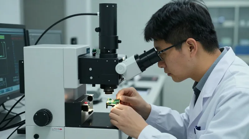
Quality Assurance: The Ubytelink Testing Protocol
The Ubytelink testing protocol is a rigorous, multi-faceted validation framework designed to ensure that every 400G FR4 module exceeds industry benchmarks for performance, reliability, and interoperability. By combining automated precision with high-stress environmental modeling, Ubytelink guarantees that its solutions maintain 99.999% uptime in the most demanding hyperscale and enterprise environments.
Advanced Signal Integrity and BER Analysis
At the core of our quality assurance is Bit Error Rate (BER) testing and Eye-Diagram analysis. Given that 400G FR4 utilizes PAM4 modulation, signal clarity is paramount. Our labs use high-performance oscilloscopes and bit-error rate testers (BERT) to visualize signal quality. A clean 'eye' opening in the diagram indicates low jitter and high noise margin, ensuring that data transmission remains error-free even over the maximum 2km reach of the FR4 specification.
| Test Category | Key Parameters Evaluated | Ubytelink Benchmark |
|---|---|---|
| Optical Performance | TX Power, RX Sensitivity, Extinction Ratio | Surpasses IEEE 802.3cu standards |
| Signal Integrity | TDECQ, Eye Mask Margin, Jitter Analysis | Optimized for PAM4 stability |
| Bit Error Rate | Pre-FEC and Post-FEC Error Rates | Zero post-FEC errors during 24h burn-in |
| Environmental | High/Low Temperature Cycling, Humidity | Stable operation 0°C to 70°C (C-Temp) |
Environmental Stress and Reliability Validation
Hardware failure in a 400G network can result in massive data throughput loss. To mitigate this, Ubytelink subjects modules to rigorous temperature cycling and accelerated aging tests. These tests simulate years of operational wear in a matter of weeks, allowing us to calculate the Mean Time Between Failures (MTBF) with high statistical confidence. By stressing the TOSA and ROSA components under extreme thermal conditions, we eliminate 'infant mortality' failures before the product ever reaches a customer's rack.
- What is the importance of TDECQ in 400G FR4 testing?
Transmitter and Dispersion Eye Closure Quaternary (TDECQ) is a critical metric for PAM4 signals. It measures the power penalty of a real transmitter compared to an ideal one, ensuring the module can handle dispersion over 2km of fiber without signal degradation. - How does Ubytelink verify interoperability?
Every module is tested in a real-world multi-vendor testbed containing the latest switches and routers from Cisco, Arista, Juniper, and NVIDIA (Mellanox) to ensure seamless plug-and-play compatibility. - What is the standard burn-in period for Ubytelink modules?
We implement a minimum 24-hour continuous traffic burn-in at elevated temperatures for every production batch to ensure component stability and long-term performance consistency.
This holistic approach to quality assurance ensures that Ubytelink 400G FR4 modules are not just functional, but optimized for the sustained high-density traffic of modern global networks. By investing in these premium testing protocols, we provide our clients with the confidence to scale their infrastructure without the risk of optical bottlenecks or hardware-related downtime.
Real-World Applications: From AI Clusters to Global DCI

Real-World Applications: From AI Clusters to Global DCI
Ubytelink 400G FR4 modules serve as the critical infrastructure link for modern digital ecosystems, offering a high-performance solution for 2km reaches that eliminates the bandwidth bottlenecks common in legacy 100G architectures. By leveraging CWDM4 technology, these modules facilitate seamless data flow across high-radix switches, making them the preferred choice for enterprises scaling their computational power for Artificial Intelligence and global cloud services.
Empowering AI Clusters and High-Performance Computing (HPC)
In the realm of AI model training, such as Large Language Models (LLMs), the demand for GPU-to-GPU communication is unprecedented. Ubytelink 400G FR4 QSFP-DD modules are deployed within these clusters to provide the low-latency interconnects required for parameter synchronization. Unlike longer-reach solutions that might introduce unnecessary power consumption, the FR4 specification is optimized for the 'sweet spot' of data center internal fabrics, ensuring that massive datasets move between compute nodes with minimal jitter and maximum throughput.
Streamlining Campus-Scale Data Center Interconnects (DCI)
For hyper-scale providers operating campus-style environments, connecting multiple data center halls within a 2km radius is a frequent challenge. Ubytelink’s 400G FR4 solutions allow for a high-density transition from 100G to 400G without requiring a complete fiber overhaul. By using just one pair of single-mode fibers (SMF) to carry four wavelengths, operators can maximize their existing duct space while providing the massive pipe needed for synchronous data replication and disaster recovery sites.
| Application Scenario | Primary Challenge | Ubytelink 400G FR4 Benefit | Network Layer |
|---|---|---|---|
| AI/ML Training | High Latency/Jitter | Low-latency PAM4 modulation | Leaf-Spine / Fabric |
| Enterprise DCI | Fiber Scarcity | CWDM multiplexing over 1 pair SMF | Inter-building / Campus |
| Cloud Edge | Power/Thermal Density | Optimized <10W power consumption | Edge Aggregation |
| Financial Trading | Reliability/Uptime | Rigorous BER and Temp testing | Core/Aggregation |
Case Study: Global Cloud Service Provider Deployment
A leading Tier-2 cloud provider recently integrated Ubytelink 400G FR4 modules to upgrade their spine-to-leaf architecture. Facing a 300% increase in traffic from containerized applications, the provider utilized Ubytelink’s interoperability-tested modules to achieve a zero-packet-loss environment. This deployment reduced the cost-per-bit by approximately 40% compared to legacy 100G solutions while maintaining a power envelope that stayed within existing cooling capacities.
Implementation Strategy FAQ
- Can Ubytelink 400G FR4 modules interoperate with DR4 modules?
Directly, no. FR4 uses wavelength division multiplexing (CWDM4) over a single fiber pair, whereas DR4 uses parallel fiber (PSM4). However, they can communicate via a breakout switch or a gearbox-equipped router that supports both formats. - What is the maximum power consumption of these modules in a high-density AI rack?
Ubytelink 400G FR4 modules are designed for high efficiency, typically consuming less than 10W per module, which is critical for maintaining thermal stability in densely packed AI server racks. - Are these modules suitable for 5G backhaul applications?
Yes, for short-reach metro aggregation points within 2km, the 400G FR4 is an excellent choice for 5G core networks requiring massive throughput and ultra-reliable connectivity.
As data demands continue to escalate, the reliability of your optical transceivers becomes the defining factor in your network's success. Ubytelink 400G FR4 modules offer the perfect synthesis of distance, speed, and durability for global mission-critical infrastructure. Don't let your connectivity be a bottleneck. Contact Ubytelink's technical team today to request a demo or a custom quote for your next high-speed upgrade.