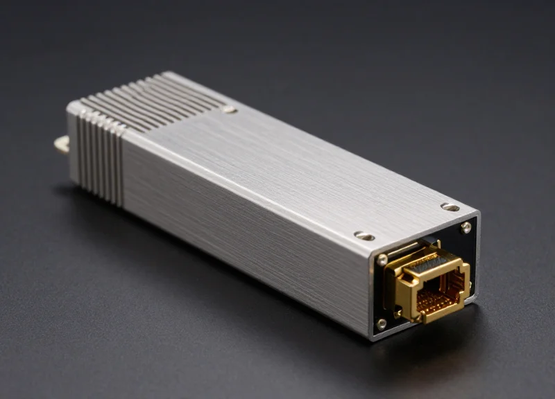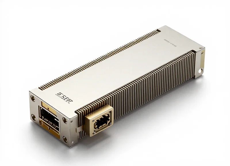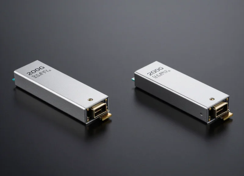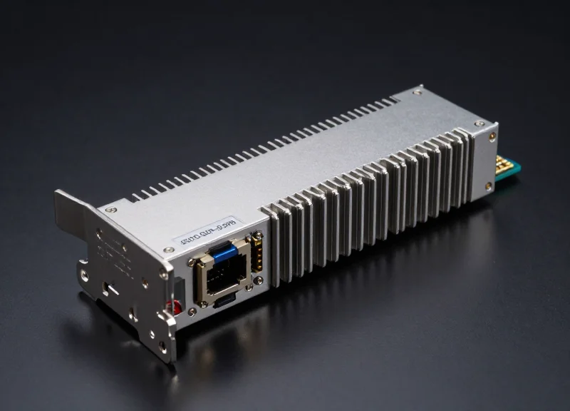
As data centers transition to 800G to meet the insatiable demands of AI and Machine Learning workloads, the 800G QSFP-DD SR8 has emerged as a critical component for short-reach high-density connectivity. This article provides a comprehensive technical breakdown of the SR8's architecture, helping network engineers and IT decision-makers navigate the complexities of next-generation optical hardware.
The Evolution of 800G Connectivity

The Evolution of 800G Connectivity
The shift to 800G connectivity marks a pivotal milestone in data center evolution, driven by the insatiable bandwidth demands of Artificial Intelligence (AI) training, hyperscale cloud computing, and massive data throughput requirements. As 400G systems reached their capacity limits, the industry transitioned to 800G by doubling lane speeds and density, leveraging 112G SerDes technology to maintain the existing physical footprint while doubling the total capacity per port. This evolution is not merely a speed increase but a fundamental redesign of how optical modules handle electrical signaling and thermal management.
From 400G to 800G: Scaling the Bandwidth Wall
The primary catalyst for the 800G era was the maturation of 112G PAM4 (Pulse Amplitude Modulation) signaling. While 400G modules typically relied on 8 lanes of 56G PAM4, 800G architectures utilize 8 lanes of 112G PAM4. This shift allows for higher radix switches, enabling network architects to build flatter, more efficient leaf-spine fabrics that reduce latency—a critical requirement for modern machine learning clusters.
| Feature | 400G QSFP-DD | 800G QSFP-DD |
|---|---|---|
| Electrical Lane Speed | 56G PAM4 | 112G PAM4 |
| Number of Lanes | 8 Lanes | 8 Lanes |
| Aggregate Bandwidth | 400 Gbps | 800 Gbps |
| Typical SerDes Tech | 56G-VSR | 112G-VSR |
The Strategic Dominance of QSFP-DD
The QSFP-DD (Quad Small Form-factor Pluggable Double Density) form factor was chosen as the primary vehicle for 800G due to its exceptional backward compatibility and density. By maintaining a similar mechanical footprint to previous generations, QSFP-DD allows network operators to use legacy 400G and 100G modules in the same ports, protecting existing infrastructure investments. This 'backwards-compatible' nature has given it a significant edge over competing form factors like OSFP in mainstream enterprise and service provider environments.
- Why move to 800G now instead of waiting for 1.6T?
The 112G SerDes ecosystem has reached a level of commercial maturity that offers the best balance of cost, power efficiency, and immediate availability for AI scaling. - What is the role of SR8 in this evolution?
SR8 refers to 'Short Range' using 8 pairs of multi-mode fiber, providing a cost-optimized solution for the internal data center connections that represent the bulk of 800G deployments. - How does 800G impact power-per-bit?
By doubling the data rate within the same form factor, 800G modules significantly reduce the power consumption per bit compared to using multiple 400G links.
Decoding the 'SR8' Nomenclature
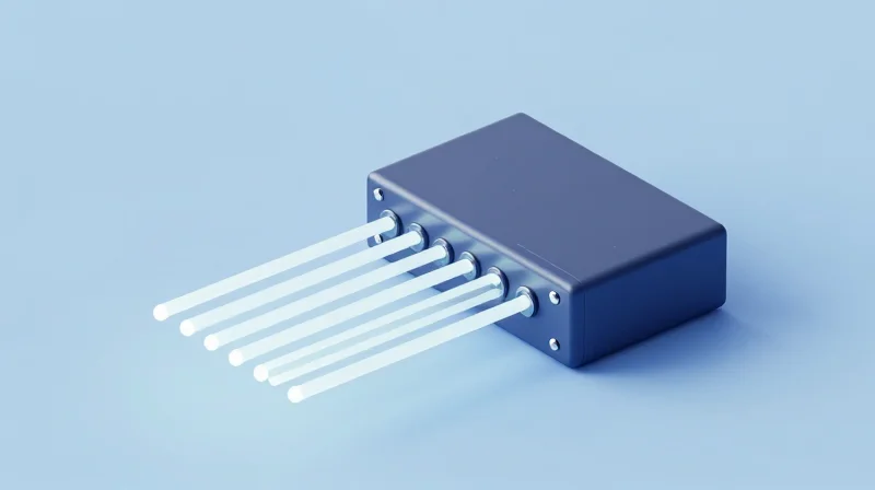
The designation 'SR8' is a structured technical shorthand defined by the IEEE 802.3 standards and Multi-Source Agreements (MSAs) to describe the reach, medium, and lane count of an optical module. In the context of 800G QSFP-DD, 'SR' stands for Short Reach, typically indicating a distance up to 100 meters over multi-mode fiber, while the '8' signifies that the module utilizes eight distinct pairs of fiber (16 fibers total in an MPO-16 connector) to transmit and receive data in parallel.
The 'SR' Designation: Short Reach and Multi-mode Fiber
The 'SR' prefix refers to 'Short Reach' applications, which are the backbone of intra-rack and rack-to-rack connectivity within data centers. These modules operate at a wavelength of 850nm using Vertical-Cavity Surface-Emitting Laser (VCSEL) technology. VCSELs are highly cost-effective and power-efficient compared to the single-mode lasers used in long-haul optics. However, due to modal dispersion inherent in multi-mode fiber (MMF), the distance is capped. For 800G SR8, the reach is generally 60m on OM3 fiber and up to 100m on OM4 or OM5 fiber.
Decoding the '8': Parallel Transmission and MPO Connectors
The '8' indicates the number of optical lanes. Unlike 'DR4' or 'FR4' modules which may use wavelength division multiplexing (WDM) to combine signals onto a single fiber pair, SR8 uses a parallel optical interface. Each of the 8 lanes carries a 100G PAM4 signal. This 8x100G architecture is specifically designed to match the 8-lane electrical interface of the QSFP-DD (Double Density) form factor, eliminating the need for complex optical muxing/demuxing within the module and thereby reducing latency and heat generation.
| Term | Full Form | Technical Meaning |
|---|---|---|
| SR | Short Reach | 850nm VCSEL transmission over Multi-mode Fiber (MMF). |
| 8 | Eight Lanes | Parallel transmission using 8 Tx and 8 Rx fibers (16 total). |
| PAM4 | Pulse Amplitude Modulation | The modulation format encoding 2 bits per symbol at 53.125 GBaud. |
| MPO-16 | Multi-fiber Push-On | The physical connector interface required for 8-lane parallel fiber. |
Standardization and IEEE 802.3ck Compliance
The 800G SR8 nomenclature aligns with the IEEE 802.3ck project, which defines the 100 Gb/s per lane electrical interface. By maintaining an 8-lane configuration both electrically and optically, the SR8 module ensures a 1:1 mapping between the host SerDes and the optical engine. This simplicity is critical for the massive scale-out of AI/ML clusters where hundreds of thousands of these connections are deployed simultaneously.
- Why is the lane count increasing to 8 for SR optics?
As per-lane speeds reached 100G, using 8 lanes became the most efficient way to achieve 800G total throughput while maintaining backward compatibility with the QSFP-DD host ports. - Does SR8 require a specific connector?
Yes, it typically requires an MPO-16 or a dual MPO-12 connector to handle the 16 fibers (8 transmit, 8 receive) necessary for parallel operation. - Can SR8 be broken down into lower speeds?
Yes, one of the primary advantages of the '8' lane architecture is its ability to support breakout configurations, such as 2x400G SR4 or 8x100G SR1, providing flexibility in leaf-spine architectures.
Technical Architecture: 100G PAM4 Technology
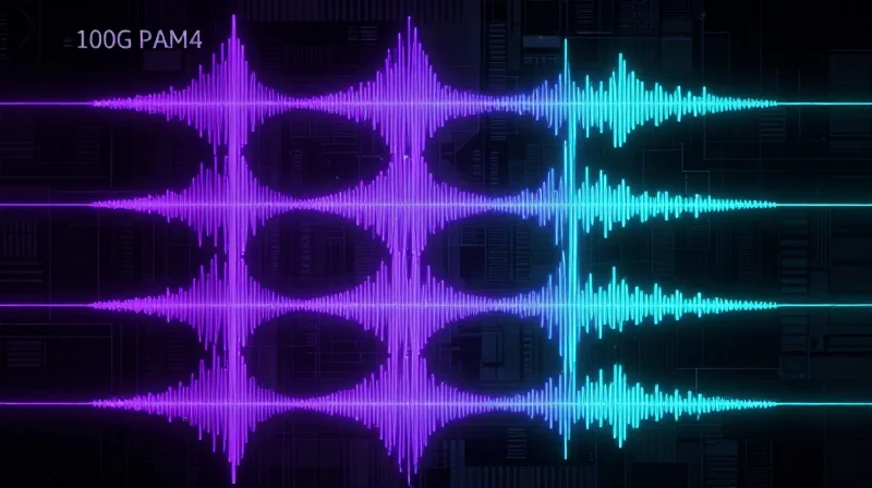
The 800G QSFP-DD SR8 transceiver relies on 100G PAM4 (Pulse Amplitude Modulation 4-level) technology to deliver a total throughput of 800 Gbps by utilizing eight parallel lanes, each operating at 106.25 Gbps. Unlike traditional binary signaling, PAM4 transmits two bits per symbol by using four distinct signal levels, effectively doubling the bandwidth density without requiring a proportional increase in optical baud rate or physical fiber count.
PAM4 vs. NRZ: Why 100G Per Lane?
As data centers transitioned from 400G to 800G, the physical limitations of NRZ (Non-Return to Zero) became a bottleneck. To achieve 100G per lane using NRZ, the required Nyquist frequency would exceed the capabilities of standard PCB materials and VCSEL components. PAM4 solves this by using four voltage levels (00, 01, 10, 11), allowing a baud rate of 53.125 GBaud to carry 106.25 Gbps of data per lane, maintaining manageable signal integrity while doubling capacity.
| Feature | NRZ (Traditional) | PAM4 (800G Standard) |
|---|---|---|
| Voltage Levels | 2 (High/Low) | 4 (0, 1, 2, 3) |
| Bits per Symbol | 1 bit | 2 bits |
| Baud Rate for 100G | 100 GBaud | 53.125 GBaud |
| SNR Requirement | Lower | Higher (+9.5dB penalty) |
The 8x100G Interface and DSP Integration
The architecture of the 800G QSFP-DD SR8 features an 800GAUI-8 electrical interface, which facilitates high-speed communication between the host ASIC and the transceiver. A critical component within this architecture is the Digital Signal Processor (DSP). The DSP performs high-speed analog-to-digital conversion and equalization to compensate for channel impairments such as chromatic dispersion and multi-path interference in multi-mode fiber (MMF). This processing is essential for meeting the strict TDECQ (Transmitter Dispersion and Eye Closure Quaternary) specifications required for 800G interoperability.
Mandatory Forward Error Correction (FEC)
Because PAM4 signaling reduces the eye height compared to NRZ, the signal-to-noise ratio (SNR) is significantly lower, leading to a higher native Bit Error Rate (BER). To achieve error-free transmission, 800G SR8 modules require mandatory Forward Error Correction. Specifically, KP4 FEC (RS-544) is utilized on the host side to identify and correct bit errors in real-time, ensuring the link meets the standard reliability requirements for enterprise and hyperscale data centers.
- Why does 800G SR8 use 8 lanes instead of 4?
Current VCSEL and DSP technology is optimized for 100G per lane; using 8 lanes allows for 800G total throughput while keeping the individual lane components within a mature and cost-effective power envelope. - What is the role of the Gearbox in 800G modules?
In many 800G implementations, the Gearbox function within the DSP maps the electrical lanes from the host to the optical lanes, ensuring the signaling rates match between the input and output stages. - Does PAM4 increase power consumption?
Yes, PAM4 requires more complex DSP processing and linear drivers compared to NRZ, which is why 800G QSFP-DD modules emphasize advanced thermal management to handle the increased power density.
Physical Layer Specs: Wavelength and Fiber Requirements
Physical Layer Specs: Wavelength and Fiber Requirements
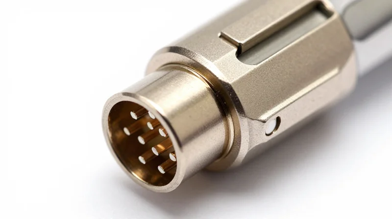
The physical layer of the 800G QSFP-DD SR8 transceiver is defined by its use of 850nm Vertical-Cavity Surface-Emitting Laser (VCSEL) technology and multi-mode fiber (MMF). It utilizes eight parallel lanes, each operating at 100Gbps, requiring a specialized MPO-16 connector to facilitate the 16-fiber (8 transmit, 8 receive) interface necessary for short-range high-density data center links.
850nm VCSEL Technology: The Engine of Short Reach
VCSELs are the industry standard for Short Reach (SR) optical communications due to their low power consumption and cost-effective manufacturing compared to edge-emitting lasers used in single-mode optics. In an 800G SR8 module, an array of eight VCSELs converts electrical PAM4 signals into optical pulses. Because 850nm light is highly susceptible to modal dispersion, the quality of the glass fiber is the primary determinant of signal integrity and maximum transmission distance.
Comparing Multi-mode Fiber (MMF) Performance
| Fiber Type | Effective Modal Bandwidth | Max Reach (800G SR8) | Application Note |
|---|---|---|---|
| OM3 | 2000 MHz·km | 60 Meters | Legacy support, not recommended for new 800G builds. |
| OM4 | 4700 MHz·km | 100 Meters | The standard choice for enterprise data centers. |
| OM5 | 4700 MHz·km | 100 Meters | Wideband MMF, supports future wavelength multiplexing. |
The MPO-16 Optical Interface
Connectivity for 800G SR8 is handled by the MPO-16 (Multi-fiber Push-On) connector. This interface features a single row of 16 fibers, providing 8 dedicated channels for transmitting and 8 for receiving. This differs from the 400G SR4, which typically uses an MPO-12. The MPO-16 connector employs a unique keying position to prevent accidental mating with MPO-12 or MPO-24 hardware, ensuring that the precision-aligned VCSEL arrays meet the fiber cores without excessive insertion loss.
Common Questions on Physical Layer Compatibility
- Can I use OM4 fiber for 100-meter 800G links?
Yes, OM4 is the recommended minimum for achieving the full 100-meter reach specified by the IEEE 802.3ck standard for SR8 modules. - Is the MPO-16 connector compatible with existing MPO-12 patch panels?
No, MPO-16 uses a different mechanical keying to prevent incorrect insertion. Upgrading to 800G SR8 typically requires new MPO-16 patch cables and compatible distribution frames. - Why is OM5 considered 'Wideband' if the reach is the same as OM4?
OM5 is optimized for multiple wavelengths (850nm to 950nm). While 800G SR8 only uses 850nm, OM5 provides better future-proofing if the network later adopts SWDM (Shortwave Wavelength Division Multiplexing) technologies.
Power Consumption and Thermal Efficiency
Power Consumption and Thermal Efficiency
The 800G QSFP-DD SR8 module operates within a typical power envelope of 12W to 16W, a significant increase over previous generations that necessitates sophisticated thermal dissipation techniques. Managing this heat is critical for maintaining the longevity of the Vertical-Cavity Surface-Emitting Laser (VCSEL) components and ensuring signal integrity across the 8-lane 100G PAM4 architecture. The transition to 800G necessitates a move toward 7nm or 5nm CMOS processes for the Digital Signal Processor (DSP) to maintain a sustainable power-per-bit ratio.
Power Profile Comparison: 400G vs. 800G
| Parameter | 400G QSFP-DD SR8 | 800G QSFP-DD SR8 |
|---|---|---|
| Typical Power Consumption | 8W - 10W | 12W - 16W |
| Power per 100G Lane | 2.0W - 2.5W | 1.5W - 2.0W |
| DSP Node Process | 16nm / 7nm | 7nm / 5nm |
| Max Operating Temp | 70°C (Commercial) | 70°C (Commercial) |
Thermal Mitigation in the QSFP-DD Form Factor
The QSFP-DD (Quad Small Form-factor Pluggable Double Density) MSA has evolved to support these higher thermal loads through improved integrated heat sink designs and optimized cage ventilation. The 'Type 2' QSFP-DD modules often feature a protruding nose or enhanced fin structures to increase the surface area available for convection. Furthermore, the internal layout of the SR8 module is engineered to isolate the heat-sensitive VCSEL array from the heat-generating DSP, using thermal interface materials (TIMs) with high thermal conductivity to shunt heat toward the module's outer shell.
- How does the 800G SR8 maintain efficiency compared to 400G?
While the total power consumption is higher, the 800G SR8 is more efficient on a per-gigabit basis. By utilizing advanced 5nm DSPs and more efficient VCSEL drivers, the energy required to transmit each bit of data is reduced by approximately 20-30% compared to legacy 400G systems. - What happens if the module exceeds the 16W thermal threshold?
Exceeding the thermal threshold triggers internal safety mechanisms, typically resulting in the DSP throttling performance or the module shutting down. Prolonged exposure to high heat can degrade the VCSELs, leading to increased Bit Error Rates (BER) and eventual hardware failure. - Is liquid cooling required for 800G QSFP-DD SR8?
Currently, most 800G SR8 deployments rely on high-velocity air cooling and optimized heat sink designs. However, as port density increases in 51.2T switches, some data center architectures are exploring immersion or cold-plate liquid cooling to manage the aggregate heat of 32 or more modules in a 1U chassis.
Critical Use Cases in AI and Hyperscale Data Centers

Critical Use Cases in AI and Hyperscale Data Centers
The adoption of 800G QSFP-DD SR8 technology is driven primarily by the need for massive 'East-West' traffic capacity within the data center, where short-reach multi-mode fiber (MMF) remains the most cost-effective medium for links under 100 meters. These modules are specifically designed to meet the rigorous bandwidth and latency demands of AI training workloads and the rapid expansion of hyperscale cloud infrastructures.
High-Performance GPU Clusters and AI Fabrics
In artificial intelligence and machine learning (AI/ML) environments, thousands of GPUs are interconnected to function as a single massive compute engine. The 800G SR8 module is critical here, facilitating the backend network (often referred to as the AI Fabric) where low latency and high-throughput communication are non-negotiable. By utilizing 8x100G lanes, these modules allow for seamless data exchange between GPU servers and Top-of-Rack (ToR) switches, ensuring that the compute resources are never bottlenecked by the network interconnect.
Leaf-Spine Connectivity in Hyperscale Networks
Hyperscale data centers utilize a Clos or leaf-spine topology to ensure predictable latency and high availability. As these facilities transition from 400G to 800G, the QSFP-DD SR8 allows operators to double their port density without altering their existing cable infrastructure, provided they use MPO-16 multi-mode cabling. This upgrade path is essential for supporting the next generation of 51.2T and 102.4T switching silicon, where 800G interfaces are the standard for high-density radix configurations.
| Use Case Scenario | Primary Benefit | Recommended Distance |
|---|---|---|
| AI Training (Back-end Fabric) | Sub-microsecond latency and 800Gbps throughput per port. | Up to 50m (OM3) / 100m (OM4/5) |
| Leaf-to-Spine Interconnect | Doubles capacity over 400G while maintaining QSFP form factor compatibility. | Up to 100m (OM4/OM5) |
| High-Density Switch-to-Switch | Maximizes bandwidth density in 1U/2U chassis configurations. | Short-reach intra-rack (3m - 20m) |
Deployment Considerations and FAQs
- Can 800G SR8 be used for breakout applications?
Yes, it is common to break out one 800G SR8 port into two 400G SR4 or eight 100G SR links, providing massive flexibility for connecting high-speed switches to lower-speed legacy servers. - Why choose SR8 over DR8 (Single-Mode) in AI clusters?
Cost is the primary factor. SR8 modules and MMF cabling are significantly less expensive than DR8 (Single-Mode) equivalents for links within the 100-meter range typical of a single data hall. - Is OM5 fiber necessary for 800G SR8?
While OM4 supports the full 100m distance, OM5 offers better performance and future-proofing for short-wave division multiplexing (SWDM) if the network eventually migrates beyond 850nm.
Comparison: 800G SR8 vs. 800G DR8 and FR8
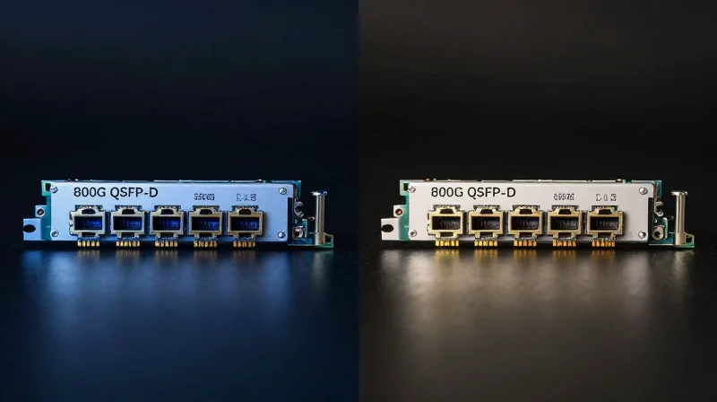
Selecting the appropriate 800G transceiver involves a strategic balance between transmission reach, fiber infrastructure costs, and power efficiency. While the 800G SR8 is the definitive choice for ultra-short, high-density connections using multi-mode fiber, the DR8 and FR8 variants provide the necessary reach for larger data center fabrics and inter-building links using single-mode fiber.
Technical Comparison: Reach, Media, and Modulation
| Feature | 800G SR8 | 800G DR8 | 800G FR8 |
|---|---|---|---|
| Transmission Distance | Up to 60m (OM3) / 100m (OM4) | Up to 500m | Up to 2km |
| Fiber Type | Multi-mode (MMF) | Single-mode (SMF) | Single-mode (SMF) |
| Connector Type | MPO-16 / MPO-12 | MPO-12 / MPO-16 | Duplex LC or MPO |
| Wavelength | 850nm VCSEL | 1310nm SiPh/EML | 1310nm CWDM / EML |
| Typical Power Consumption | 12W - 14W | 15W - 17W | 16W - 19W |
Analyzing Cost and Power Efficiency
The 800G SR8 module is optimized for cost-sensitive, short-reach applications like Top-of-Rack (ToR) to Leaf switches. Because it utilizes Vertical-Cavity Surface-Emitting Laser (VCSEL) technology, it consumes significantly less power and is cheaper to manufacture than the DR8 and FR8 versions. However, the requirement for Multi-mode Fiber (MMF) can lead to higher cabling costs in large-scale deployments compared to the thinner, more affordable Single-mode Fiber (SMF) used by DR8 and FR8.
In contrast, the 800G DR8 and FR8 modules use Silicon Photonics (SiPh) or Externally Modulated Lasers (EML). While these components increase the module's per-unit price and power draw, they are essential for spanning the distances required in spine-to-leaf architectures and hyperscale clusters where 100 meters is insufficient.
Deployment Considerations FAQ
- Can I use 800G SR8 for leaf-to-spine connections?
Yes, provided the distance is under 100 meters. For many modern hyperscale AI clusters, SR8 is the preferred choice for leaf-to-spine due to its lower latency and power profile. - Why choose DR8 over FR8?
DR8 is optimized for 500m reaches and is often more cost-effective for internal data center rows. FR8 is specialized for 2km reaches, making it better for connecting different data center halls or campus buildings. - Are these modules backward compatible?
Compatibility depends on the breakout cables and switch OS. Generally, SR8 can break out into 2x 400G SR4, while DR8 can break out into 2x 400G DR4 or 8x 100G DR1.
Interoperability and Forward Error Correction (FEC)
The Necessity of KP4 FEC in 100G-per-Lane Architectures
At the 800G performance tier, signal degradation becomes a primary concern due to the high-frequency nature of 112Gbps PAM4 lanes. To maintain a reliable link, the 800G QSFP-DD SR8 relies on KP4 Forward Error Correction (RS-FEC 544, 514) as defined in IEEE 802.3ck. This error correction mechanism is mandatory because the raw, or Pre-FEC, bit error rate (BER) of 100G-per-lane systems typically exceeds the acceptable threshold for data integrity. By utilizing KP4 FEC, the system can correct burst errors and random noise, successfully bringing a Pre-FEC BER of approximately 2.4e-4 down to a Post-FEC target of less than 1e-13.
Interoperability and Standard Compliance
Interoperability between different networking vendors is ensured by adherence to the QSFP-DD800 MSA and IEEE 802.3db standards. For 800G SR8 modules to work effectively across a heterogeneous fabric, both the host silicon (ASIC/DSP) and the optical module must support compatible FEC engines. While some proprietary FEC schemes exist for extended reach, the standard SR8 deployment mandates the use of common KP4 parameters to prevent link-up failures and frame loss when mixing transceiver brands.
| Parameter | Target Specification | Impact on Link |
|---|---|---|
| FEC Algorithm | KP4 RS(544, 514) | Mandatory for 100G/Lane |
| Pre-FEC BER Limit | 2.4 × 10^-4 | Maximum allowable raw error rate |
| Post-FEC BER Target | < 10^-13 | Ensures error-free data delivery |
| FEC Latency | ~100-200 ns | Added delay due to processing |
Common Interoperability Challenges
- Can 800G SR8 interoperate with 400G SR4?
Yes, provided the 800G port can be broken down into two 400G interfaces and the FEC settings are aligned, typically requiring both ends to use KP4 FEC. - What happens if FEC is disabled on an SR8 link?
The link will likely fail to stay up or experience severe packet loss, as the raw PAM4 signal at 112Gbps is too noisy to meet standard data integrity requirements without correction. - Does FEC affect latency in AI applications?
Yes, KP4 FEC adds a small amount of nanosecond-level latency. While negligible for most data center tasks, it is a factor optimized by DSP designers in ultra-low-latency AI clusters.
Deployment Challenges and Best Practices
Critical Challenges in 800G SR8 Implementation
Deploying 800G QSFP-DD SR8 optics introduces unprecedented requirements for physical layer precision, as the transition to 112G PAM4 signaling significantly reduces the margin for signal degradation. Unlike 400G systems, 800G links are hyper-sensitive to return loss and attenuation, meaning that minor imperfections in the fiber plant that were negligible at lower speeds can now cause total link failure or excessive bit errors.
Thermal Management and Power Density
The QSFP-DD form factor for 800G SR8 typically consumes between 14W and 18W. In a fully populated 1U switch with 32 ports, this generates a massive heat load. Best practices dictate the use of high-efficiency cooling fans and optimized airflow patterns. Cable management must be meticulously organized to prevent 'cable dams' at the front of the switch, which can obstruct intake air and lead to thermal throttling of the transceivers.
Fiber Infrastructure Hygiene
| Deployment Aspect | Best Practice | Impact on Performance |
|---|---|---|
| Connector Inspection | Use automated MPO-16 fiber scopes for every connection. | Prevents dust-induced signal scattering and high Pre-FEC BER. |
| Cleaning Protocols | Employ dry cleaning with MPO-specific clickers; avoid wet cleaning unless necessary. | Reduces the risk of residue streaks that cause reflectance issues. |
| Bend Radius | Maintain a minimum bend radius of 10x the cable diameter. | Minimizes macro-bending losses which are critical for 112G signaling. |
| Port Plugging | Keep dust caps on until the exact moment of insertion. | Protects the sensitive 16-lane optical sub-assembly from ambient debris. |
Link Validation and FEC Monitoring
Validating an 800G link goes beyond verifying a 'Link Up' status. Network engineers must monitor the Pre-FEC (Forward Error Correction) Bit Error Rate. A link may appear functional while FEC is active, but if the Pre-FEC BER is consistently high, the link lacks the 'headroom' necessary to survive minor environmental shifts or laser aging. Testing should include stress-testing the link with real-world traffic patterns to ensure the KP4 FEC is not working near its correction threshold.
- Can I reuse existing MPO-12 cabling for 800G SR8?
No. 800G SR8 requires an MPO-16 connector to support its 8-transmit and 8-receive lanes. Reusing MPO-12 or MPO-24 cabling will result in physical misalignment and no link. - Is OM4 fiber sufficient for 800G SR8?
Yes, OM4 is supported up to 60 meters, while OM5 is recommended for reaches up to 100 meters due to its better performance at higher wavelengths and modal bandwidth. - How often should connectors be cleaned?
Connectors must be inspected and cleaned every time they are mated. The high power density of 800G lasers can actually 'bake' dust onto the fiber end-face, causing permanent damage.
The 800G QSFP-DD SR8 represents the pinnacle of current multi-mode optical technology, offering the density and speed required for the next decade of digital infrastructure. To ensure your network is ready for the 800G leap, contact our technical team today for a compatibility assessment and customized optical solution roadmap.