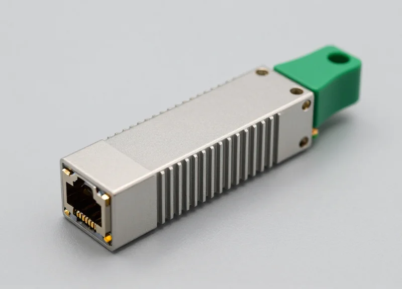
As global data demands skyrocket, power consumption has become the critical bottleneck for modern hyperscale environments. 400G technology represents more than just a bandwidth jump; it is a fundamental shift in energy-per-bit efficiency. This guide explores the technical innovations driving 400G to become the benchmark for sustainable high-speed networking.
The Evolution of Power Density: From 100G to 400G

The Evolution of Power Density: From 100G to 400G
The transition from 100G to 400G marks a paradigm shift in data center economics, where efficiency is defined by the energy required to transport a single bit of data rather than total chassis consumption. While a single 400G transceiver consumes more absolute power than its 100G predecessor, it delivers four times the bandwidth, resulting in a significant reduction in power-per-gigabit (W/Gbps). In modern hyperscale environments, migrating to 400G architectures typically yields a 50% to 75% improvement in power efficiency compared to scaling legacy 100G infrastructure to meet the same capacity requirements.
Key Drivers of 400G Energy Efficiency
The leap in efficiency is primarily driven by two technological breakthroughs: the shift from NRZ (Non-Return to Zero) to PAM4 (Pulse Amplitude Modulation 4-level) and the advancement of CMOS silicon lithography. PAM4 allows for doubling the data rate within the same bandwidth by transmitting two bits per symbol, effectively halving the relative power cost of high-speed signal processing. Simultaneously, the industry’s move from 16nm and 28nm silicon processes to 7nm and 5nm nodes has enabled switch ASICs to process massive throughput with lower leakage current and better thermal performance.
| Metric | 100G (QSFP28) | 400G (QSFP-DD) |
|---|---|---|
| Typical Transceiver Power | 3.5W - 5W | 12W - 15W |
| Bandwidth Capacity | 100 Gbps | 400 Gbps |
| Efficiency (Watts per Gbps) | ~0.045 W/Gbps | ~0.033 W/Gbps |
| Modulation Type | NRZ | PAM4 |
| Relative Space Footprint | 1x Density | 4x Density (Same 1U) |
Understanding the Power-per-Bit Advantage
When comparing 400G to 100G, the focus must remain on density. A single 1RU switch supporting 32 ports of 400G provides 12.8Tbps of throughput. To achieve this same capacity using 100G technology, an operator would require multiple switches, more cabling, and significantly more rack space, all of which contribute to higher 'ghost' power consumption—energy used by cooling systems and auxiliary hardware. By consolidating throughput into high-density 400G ports, data centers reduce the complexity of their electrical fabric, leading to a leaner, more energy-resilient network core.
- How does PAM4 impact power consumption?
PAM4 increases data density by using four signal levels instead of two. While it requires more complex Digital Signal Processing (DSP) which adds some power overhead, the net gain in bandwidth per clock cycle results in a lower total power cost per bit compared to traditional NRZ. - Does 400G infrastructure require more cooling?
Yes, on a per-port basis, 400G optics run hotter than 100G optics. However, because fewer switches and cables are needed to reach the same aggregate bandwidth, the overall cooling demand for the entire facility is often lower than it would be for a comparable 100G-based network. - What role does silicon lithography play?
Smaller process nodes (like 7nm) allow more transistors to be packed into the switch ASIC with lower voltage requirements. This reduces the heat generated during high-speed packet switching, which is a critical factor in maintaining 400G power efficiency.
Core Metrics: Understanding Watts per Gigabit (W/Gbps)
Core Metrics: Understanding Watts per Gigabit (W/Gbps)
Watts per Gigabit (W/Gbps) is the foundational metric used by network architects to evaluate the energy efficiency of high-capacity networking hardware. It is calculated by dividing the total power consumption of a network interface by its maximum data throughput. In the context of 400G, this ratio represents the 'energy cost' of moving information. A lower W/Gbps value indicates a more efficient architecture, allowing service providers to scale bandwidth without a proportional increase in power bills or cooling infrastructure requirements.
Comparative Efficiency: 100G vs. 400G
| Metric | 100G QSFP28 | 400G QSFP-DD | Efficiency Delta |
|---|---|---|---|
| Throughput | 100 Gbps | 400 Gbps | 400% Increase |
| Typical Power Consumption | 15W - 24W | 12W - 20W | ~20% Lower Power Consumption |
| Efficiency (W/Gbps) | 0.15 - 0.24 W/Gbps | 0.03 - 0.05 W/Gbps | ~80% Efficiency Improvement |
Key Drivers of W/Gbps Reduction
- How does the shift to 7nm/5nm DSPs lower W/Gbps?
The transition to smaller semiconductor nodes reduces the voltage required for transistor switching. In 400G transceivers, 7nm and 5nm Digital Signal Processors (DSPs) consume significantly less power than the 16nm or 28nm chips used in older 100G modules. - Why is the form factor significant for energy metrics?
The QSFP-DD and OSFP form factors are designed for optimized heat dissipation. Better thermal management reduces the energy wasted as heat and minimizes the secondary power consumption from cooling fans. - What is the impact of PAM4 signaling on efficiency?
By using Pulse Amplitude Modulation 4-level (PAM4), 400G systems transmit two bits per symbol. This doubles the data rate over the same bandwidth compared to NRZ, effectively halving the energy required per bit of transmitted data.
Ultimately, the drive toward sub-0.05 W/Gbps is what makes 400G economically viable. By achieving this level of efficiency, data center operators can fit more ports into a single rack unit (RU) while staying within the strict power envelopes of existing facilities. This metric is the bridge between raw performance and sustainable growth in hyperscale environments.
Hardware Breakthroughs: The Role of 7nm and 5nm DSPs
The migration to 7nm and 5nm Digital Signal Processors (DSPs) is the critical hardware evolution that enables 400G network power efficiency by reducing logic power consumption by up to 50% per gigabit compared to legacy 16nm nodes. By shrinking the gate length and improving transistor density, these advanced process nodes allow transceivers to perform complex PAM4 modulation and error correction within the strict 12W to 15W thermal limits of standard form factors like QSFP-DD.
The CMOS Scaling Advantage: From 16nm to 5nm
Digital Signal Processing is the most energy-intensive function within a 400G transceiver. As data rates quadruple from 100G, the DSP must manage higher symbol rates and more complex modulation schemes. Using older 16nm FinFET technology for these tasks results in excessive heat that would exceed the cooling capacity of high-density switches. The shift to 7nm and 5nm nodes utilizes smaller transistors with lower parasitic capacitance and reduced operating voltages (Vdd), which directly scales down the dynamic power consumption according to the P=CV²f formula.
| Process Node | Relative Power Efficiency | Transistor Density | Typical 400G Application |
|---|---|---|---|
| 16nm | Baseline (100%) | Standard | Early 400G / 100G Legacy |
| 7nm | 60-70% Efficiency | 2.5x Increase | Standard 400G DR4/FR4 |
| 5nm | 45-50% Efficiency | 4.0x Increase | 400G-ZR Coherent / 800G |
Thermal Dissipation and Module Reliability
Beyond simple energy savings, the role of 5nm DSPs is crucial for maintaining the thermal integrity of the network. High-performance optical components are sensitive to heat; excessive temperatures can cause wavelength drift and accelerate the degradation of laser diodes. By reducing the power consumed by the DSP, manufacturers can allocate more of the module's thermal budget to the optical engine and integrated lasers, ensuring stable performance over the module's lifespan. This efficiency is particularly vital for 400G-ZR and ZR+ modules, which incorporate additional coherent processing that would be impossible to cool on larger process nodes.
- Why is the DSP the primary focus for 400G power reduction?
The DSP performs the heavy mathematical lifting for PAM4 signaling and Forward Error Correction (FEC), typically accounting for over 50% of the total power consumed by a 400G optical module. - How does 5nm technology impact data center cooling costs?
By lowering the heat emitted per module, 5nm DSPs reduce the required fan speeds and air conditioning load on the data center floor, leading to a significant reduction in secondary cooling costs. - What is the relationship between node size and 400G reach?
Smaller nodes like 5nm allow for more complex compensation algorithms to be integrated into the DSP without increasing heat, which enables longer transmission distances (e.g., 80km to 120km for ZR modules).
Silicon Photonics: Revolutionizing Optical Interconnect Efficiency

Silicon Photonics: Revolutionizing Optical Interconnect Efficiency
Silicon photonics (SiPh) is the foundational technology enabling the transition to sustainable 400G and 800G infrastructures by merging the high bandwidth of fiber optics with the cost-efficiency of CMOS silicon processing. By integrating lasers, modulators, and photodetectors onto a single chip, SiPh minimizes the energy-intensive transitions between electrical and optical domains that plague traditional discrete designs. This integration significantly reduces the signal power required to drive data across the interconnect, directly lowering the power-per-bit profile of the network.
Eliminating Discrete Component Losses
In conventional optics, every interface between a discrete component and the circuit board introduces parasitic capacitance and resistance. Silicon photonics addresses these inefficiencies by utilizing CMOS-compatible processes to fabricate waveguides and modulators directly on the silicon die. This monolithic approach eliminates many of the electrical junctions that traditionally dissipate energy as heat, allowing for a leaner and more efficient thermal envelope within the transceiver module.
| Metric | Discrete Optical Assemblies | Silicon Photonics (SiPh) |
|---|---|---|
| Interconnect Path | Longer traces with parasitic loss | Short, integrated waveguides |
| Component Density | Low (Discrete parts) | High (Integrated on-die) |
| Power Consumption | Higher due to electrical conversion | Lower due to integrated modulation |
| Reliability | Subject to assembly tolerances | Consistent CMOS manufacturing |
The Path to Co-Packaged Optics (CPO)
The most significant energy breakthrough offered by silicon photonics is its role in Co-Packaged Optics (CPO). By bringing the optical engine into the same physical package as the switch ASIC, the distance signals must travel over copper traces is reduced from centimeters to millimeters. This proximity removes the need for high-power SerDes (Serializer/Deserializer) reach-extension circuitry, which can account for a substantial portion of the total system power. For 400G networks, this transition is the key to maintaining a manageable power budget as port density increases.
- How does SiPh lower the laser power requirement?
By using highly efficient integrated modulators, such as silicon micro-ring resonators, the system can achieve high data rates with lower insertion loss, requiring less initial light intensity from the laser source. - Why is SiPh critical for 400G thermal management?
The integration reduces the overall power draw of the module, which leads to less heat generation. This allows for higher density deployments without exceeding the cooling capacity of standard air-cooled data center racks.
Form Factor Efficiency: QSFP-DD vs. OSFP
The Impact of Form Factor on 400G Thermal Efficiency
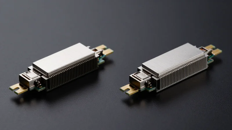
The efficiency of a 400G network is not solely defined by the silicon inside the module, but also by the physical form factor's ability to dissipate heat. While QSFP-DD offers the advantage of backward compatibility and port density, OSFP provides superior thermal headroom, allowing it to support higher-power optics like 400G-ZR+ with lower cooling-related energy overhead. The choice between these factors dictates the cooling strategy of the entire switch chassis, directly affecting the total power consumption of the data center.
Thermal Dissipation and Power Limits
QSFP-DD (Quad Small Form-factor Pluggable Double Density) utilizes a high-density connector but has a smaller surface area, which typically restricts its power envelope to approximately 12W to 14W in standard configurations. Beyond this, thermal throttling or expensive liquid cooling may be required. Conversely, OSFP (Octal Small Form-factor Pluggable) was engineered with integrated cooling fins and a larger physical footprint. This allows it to handle 15W to 20W or more, making it more efficient for high-performance coherent optics that generate significant thermal load.
| Feature | QSFP-DD | OSFP |
|---|---|---|
| Max Power (Typical) | 12W - 14W | 15W - 20W+ |
| Thermal Design | Relies on system-level heat sinks | Integrated module-level heat sink |
| Backward Compatibility | Native support for QSFP28 | Requires mechanical adapter |
| Airflow Path | Standard front-to-back | Optimized with integrated fins |
System-Level Cooling and Efficiency Trade-offs
From a total cost of ownership (TCO) perspective, the form factor influences the 'cooling tax'—the energy consumed by fans to maintain operational temperatures. Because OSFP modules manage heat more effectively at the source, they can often operate with lower fan speeds at the chassis level. QSFP-DD, while superior for density, may require higher RPMs and more power-hungry cooling systems to prevent the DSPs from reaching their thermal limits, which can diminish the overall power-per-bit advantages of the 400G transition.
- How does heat affect module power consumption?
High temperatures increase leakage current in CMOS circuits like the DSP, creating a feedback loop where increased heat leads to higher power draw and reduced component lifespan. - Is OSFP always more efficient than QSFP-DD?
Not necessarily for short-reach applications (SR4/DR4); however, for high-power long-reach (ZR/ZR+) optics, OSFP's thermal design offers a clear efficiency advantage by reducing the burden on system fans. - Why does backward compatibility matter for efficiency?
QSFP-DD allows operators to reuse existing infrastructure without adapters, reducing initial hardware waste and simplifying the power profile of mixed-speed racks.
PAM4 Modulation and its Impact on Energy Profiles
Transitioning from Non-Return-to-Zero (NRZ) to Four-Level Pulse Amplitude Modulation (PAM4) is the fundamental shift that allows 400G networks to scale capacity without a linear increase in power consumption. By transmitting two bits per symbol instead of one, PAM4 effectively doubles the data throughput at the same baud rate, allowing the underlying hardware to operate at frequencies that are more energy-efficient and easier to manage thermally.
Baud Rate Optimization and Power Gains
In traditional NRZ signaling, achieving 400G would require either 16 lanes of 25G or 8 lanes of 50G NRZ. Scaling to these speeds with NRZ would necessitate extremely high clock frequencies, leading to massive heat generation and significant signal integrity challenges. PAM4 uses four voltage levels to encode two bits of data (00, 01, 10, 11) per signal period. This increased spectral efficiency means that a 50G PAM4 lane provides the same throughput as a theoretical 100G NRZ lane, but at half the Nyquist frequency, which significantly reduces the energy required for signal transmission over physical media.
| Metric | NRZ (2-Level) | PAM4 (4-Level) |
|---|---|---|
| Bits per Symbol | 1 bit | 2 bits |
| Symbol Levels | 2 (High/Low) | 4 (0, 1, 2, 3) |
| Bandwidth Density | Baseline | 2x Baseline |
| SNR Tolerance | High | Low (Requires FEC) |
| Relative Power per Bit | Higher at 400G | 30-45% Lower at 400G |
The Role of DSP and FEC in the PAM4 Power Equation
While PAM4 is more spectrally efficient, it introduces a complexity tax because the voltage levels are closer together, making the signal more susceptible to noise. To mitigate this, 400G systems utilize advanced Digital Signal Processors (DSPs) and Forward Error Correction (FEC). While the DSP itself consumes a significant portion of the module's power, the net energy result is a major gain. By using PAM4, engineers reduce the number of high-speed lanes, lasers, and optical components required, which provides a better overall power profile than attempting to scale simpler modulation schemes to 400G levels.
- Why can't we just increase NRZ clock speeds?
Increasing NRZ speeds to 100G per lane results in exponential power loss due to signal attenuation and the copper skin effect, making it thermally unviable for compact 400G form factors. - Does PAM4 require more cooling?
While the DSP chip generates concentrated heat, the overall system-level power consumption per gigabit is lower, meaning PAM4 actually reduces the cooling requirements per unit of data transferred. - How does PAM4 impact transceiver cost?
The integration of PAM4 into DSPs reduces the bill of materials for optical components (fewer lasers and modulators), which offsets the cost of more advanced silicon.
Cooling and Thermal Management in High-Density Racks

Cooling 400G infrastructures requires a departure from traditional data center cooling due to the significant increase in heat density per rack unit. As 400G transceivers consume between 10W and 15W each, a fully populated 32-port or 64-port switch can generate massive thermal loads in a compact form factor. Maintaining optimal operating temperatures is not merely a matter of hardware longevity; it is a direct contributor to power efficiency. When components run hot, silicon leakage current increases, requiring more power to maintain the same performance levels, which in turn generates more heat—creating a recursive efficiency loss known as thermal runaway.
The Thermal Challenges of High-Density 400G Optics
The transition to 400G involves smaller, more integrated components that concentrate heat in specific areas of the PCB. Pluggable modules like QSFP-DD and OSFP have different thermal dissipation characteristics. OSFP modules, for instance, often include integrated fins to improve surface area for heat exchange, whereas QSFP-DD relies more heavily on the cage and internal chassis airflow. Proper management requires precise Computational Fluid Dynamics (CFD) modeling to ensure that air is not just moving through the rack, but is effectively stripping heat from the transceiver faces and the ASIC heat sinks.
Comparison of Cooling Methodologies for 400G Racks
| Cooling Method | Efficiency Rating | Density Capacity | Infrastructure Complexity |
|---|---|---|---|
| Traditional Air Cooling | Low to Moderate | Up to 15-20 kW/rack | Low - Standard Hot/Cold Aisle |
| Rear Door Heat Exchanger (RDHx) | High | 20-50 kW/rack | Moderate - Requires liquid loop to rack |
| Direct-to-Chip Liquid Cooling | Very High | 50-100 kW/rack | High - Requires specialized cold plates |
| Immersive Cooling | Maximum | 100+ kW/rack | Extreme - Hardware must be immersion-ready |
Optimizing Airflow and Fan Logic
Beyond the cooling medium, efficiency is gained through intelligent fan control. Modern 400G switches utilize variable-speed fans that are mapped to real-time telemetry from the optical modules and the network ASIC. By employing 'cooling-on-demand' algorithms, operators can reduce the parasitic power load of the fans—which can account for 10-15% of total device power—during periods of lower traffic or cooler ambient temperatures. Additionally, the use of blanking panels and hot-aisle containment is mandatory to prevent the recirculation of exhausted air, which can artificially spike the intake temperature of 400G ports.
Thermal Management and Efficiency FAQ
- How does ambient temperature affect 400G power efficiency?
Higher ambient temperatures force cooling fans to run at higher RPMs, increasing the 'overhead' power consumption. Furthermore, transceivers exhibit higher power leakage at elevated temperatures, reducing the overall bits-per-watt efficiency. - Is liquid cooling necessary for all 400G deployments?
No, air cooling is still viable for standard 400G deployments. However, for ultra-high-density AI clusters and hyperscale environments where rack power exceeds 25kW, liquid-assisted cooling becomes necessary to maintain stability. - What is the impact of transceiver form factor on cooling?
The OSFP form factor generally offers better thermal headroom due to its larger size and integrated heat sink, allowing for higher power envelopes (up to 15W+) compared to the tighter constraints of QSFP-DD.
Real-World Applications in Hyperscale and Edge Computing
Real-World Applications in Hyperscale and Edge Computing
The transition to 400G network power efficiency is the primary enabler for global data centers to scale sustainably, delivering a 3x to 4x reduction in power consumption per gigabit compared to legacy 100G architectures. By consolidating traffic into high-density 400G pipes, operators can meet exploding data demands from AI and 5G without a linear increase in energy costs or carbon emissions.
Hyperscale Case Studies: Meeting ESG Targets
For hyperscalers like AWS, Google, and Meta, 400G deployment is a cornerstone of their 'Net Zero' carbon commitments. By replacing four 100G links with a single 400G port, these organizations significantly reduce the physical footprint and the associated cooling load. A typical hyperscale deployment sees a power density shift from roughly 15W-20W per 100G (across four units) to approximately 10-12W for a single 400G QSFP-DD module, representing a massive efficiency gain at the port level.
| Metric | Legacy 100G (4x100G) | Modern 400G (1x400G) | Efficiency Gain |
|---|---|---|---|
| Total Power Draw | 60W - 80W | 12W - 18W | 70% - 75% Reduction |
| Switch Port Usage | 4 Ports | 1 Port | 75% Space Saving |
| Cabling Density | High (4x Duplex) | Low (1x MPO/LC) | Simplified Airflow |
Edge Computing: Efficiency at the Perimeter
In edge computing environments, where power and space are often at a premium, the adoption of 400G ZR and ZR+ optics has been revolutionary. These pluggable modules allow for high-capacity DWDM links directly from the router, eliminating the need for bulky, power-hungry external transponder equipment. This 'IP-over-DWDM' (IPoDWDM) approach reduces the total hardware stack at the edge, leading to lower operational expenditures (OPEX) and a significantly smaller carbon footprint at remote cell sites or regional points of presence (PoPs).
Common Questions on 400G Application Efficiency
- How does 400G impact the Power Usage Effectiveness (PUE) of a data center?
While PUE measures the ratio of total facility power to IT equipment power, 400G improves the overall energy profile by reducing the 'IT power' denominator for the same bandwidth, while also generating less heat per gigabit, which reduces the cooling demand (facility power). - Is 400G cost-effective for smaller edge deployments?
Yes, because the efficiency gains in power and the reduction in rack space (RU) often offset the higher initial cost of 400G optics, especially in sites where power utility rates are high. - Does the use of 400G ZR optics require specialized cooling?
400G ZR modules can consume up to 15-20W. While high, it is more efficient than a standalone transponder. However, it does require switches with optimized airflow and robust thermal management to prevent throttling.
Navigating the complexities of 400G power efficiency is essential for building a scalable, future-proof network that balances performance with environmental responsibility. Ready to optimize your infrastructure? Contact our engineering team today for a custom power assessment of your 400G roadmap.