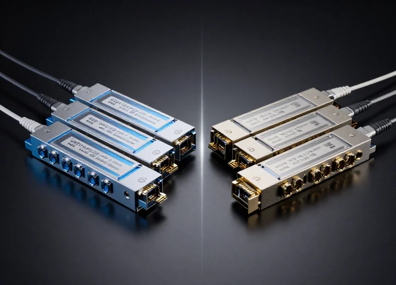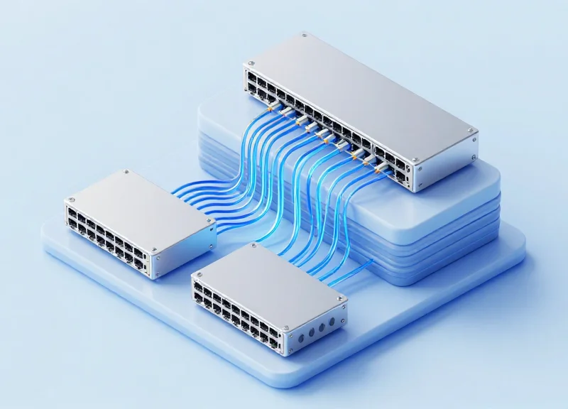
As data centers face an unprecedented surge in traffic driven by AI, machine learning, and global cloud services, traditional three-tier network architectures are reaching their limits. The industry is rapidly pivoting toward 400G Leaf-Spine topology to achieve the massive bandwidth and low-latency performance required for today's workloads. In this deep dive, we explore how this non-blocking architecture functions and why it is the cornerstone of modern digital infrastructure.
The Evolution of Data Center Design: Why Leaf-Spine?
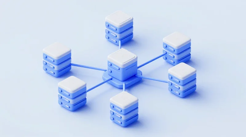
The shift to leaf-spine architecture represents a fundamental departure from legacy hierarchical networking, moving away from a model optimized for client-server communication to one designed for the massive server-to-server data flows of modern cloud environments. By collapsing the network into two tiers, leaf-spine eliminates the bottlenecks inherent in traditional spanning-tree-based designs, providing the deterministic latency and predictable performance necessary for 400G high-speed interconnects.
The Limitations of the Traditional 3-Tier Model
For decades, the standard data center design followed a three-layer hierarchy: Access, Aggregation (or Distribution), and Core. This architecture was built for 'north-south' traffic, where data primarily moves between an external user and an internal server. However, as applications transitioned to microservices and distributed computing, the traffic pattern flipped. Communication now happens predominantly between servers within the data center, known as 'east-west' traffic. In a 3-tier model, this data often has to travel up to the core and back down, creating significant latency and congestion points.
| Feature | 3-Tier Hierarchical | Leaf-Spine (2-Tier) |
|---|---|---|
| Primary Traffic Path | North-South (User to Server) | East-West (Server to Server) |
| Latency Pattern | Variable (Multi-hop) | Deterministic (Fixed-hop) |
| Loop Prevention | Spanning Tree Protocol (STP) | Layer 3 Routing / ECMP |
| Bandwidth Utilization | Partial (Blocked links) | Full (All-active paths) |
| Scalability | Complex / Port Limited | Horizontal / Granular |
Why Leaf-Spine is the Foundation for 400G
The leaf-spine topology is a 'Clos' architecture where every leaf switch (the access layer) is connected to every spine switch (the backbone layer). This ensures that any two servers in the data center are exactly the same number of hops apart. As organizations move toward 400G speeds, the inefficiencies of legacy designs become untenable. 400G requires a non-blocking fabric where Equal-Cost Multi-Path (ECMP) routing can be fully utilized to balance traffic across all available links, maximizing the massive throughput of modern QSFP-DD and OSFP transceivers.
Technical Advantages of the Two-Tier Fabric
- How does leaf-spine handle network failures?
Unlike STP which shuts down redundant links, leaf-spine uses Layer 3 routing protocols like BGP. If a spine switch fails, the network simply redistributes the load across the remaining active spine switches, resulting in minimal performance degradation. - What makes it more scalable than legacy designs?
Scaling is horizontal. To increase throughput, you add more spine switches; to increase port density, you add more leaf switches. This avoids the 'forklift upgrade' required when a legacy core switch reaches its capacity. - Why is latency more predictable in this model?
Because every leaf is connected to every spine, every path between any two servers is exactly two hops. This eliminates the 'jitter' caused by data taking different length paths through a complex hierarchy.
By adopting leaf-spine, data centers gain a flatter, faster, and more resilient network foundation. This architectural evolution is not merely a preference but a requirement for supporting the ultra-high-density workloads found in modern AI training, big data analytics, and high-frequency trading environments.
Core Components of 400G Leaf-Spine Architecture
A 400G leaf-spine architecture is built upon a high-performance foundation where hardware density and protocol efficiency converge. By utilizing high-radix switches and 400GbE optical transceivers, this topology creates a non-blocking fabric that enables seamless east-west traffic flow across modern data centers.
The Spine Layer: The High-Capacity Backbone
In a 400G design, the spine switches act as the central distribution point for all traffic. These units are characterized by extreme port density, often providing 32, 64, or even 128 ports of 400GbE in a single chassis or fixed-form factor. Unlike traditional cores, the spine does not connect to servers directly; it exists solely to aggregate and forward traffic between leaf switches, ensuring that any leaf-to-leaf path is no more than two hops away.
The Leaf Layer: Server Access and Aggregation
Leaf switches serve as the 'entry point' for the network, typically positioned at the Top-of-Rack (ToR). In a 400G topology, these switches provide downlinks to servers (often at 25G, 50G, or 100G) and utilize 400G uplinks to connect to every spine in the fabric. This layer handles crucial tasks such as VXLAN encapsulation/decapsulation and enforcement of security policies at the network edge.
Key Interconnect Technologies for 400G
| Module Type | Max Distance | Fiber Type | Common Use Case |
|---|---|---|---|
| 400G DR4 / FR4 | 500m - 2km | Single-Mode (SMF) | Longer Leaf-to-Spine links |
| 400G SR8 | 100m | Multi-Mode (MMF) | Short-range intra-row connections |
| 400G DAC | 2.5m - 3m | Twinaxial Copper | Server-to-Leaf (Top-of-Rack) |
| 400G AOC | Up to 30m | Active Optical | High-density rack-to-rack links |
Achieving Non-Blocking Performance
The true power of 400G Leaf-Spine lies in its ability to provide 'non-blocking' performance via Equal-Cost Multi-Pathing (ECMP). By utilizing L3 routing protocols—most commonly BGP—the fabric can load-balance traffic across all available spine switches. If one spine fails, the bandwidth is reduced, but the topology remains fully functional without the convergence delays associated with legacy Spanning Tree Protocol (STP).
- How many spine switches are typically required?
Most 400G deployments use 2, 4, or 8 spines depending on the desired oversubscription ratio and total number of leaf switches. - What is the standard form factor for 400G optics?
QSFP-DD and OSFP are the two dominant form factors, with QSFP-DD being the most widely adopted due to backward compatibility with QSFP28. - Is oversubscription still a factor in 400G designs?
Yes. While 1:1 (non-blocking) is possible, many data centers opt for 3:1 oversubscription to balance cost and performance for standard enterprise workloads.
The Impact of 400G Throughput on Network Capacity

The Impact of 400G Throughput on Network Capacity
The transition from 100G to 400G throughput represents a paradigm shift in data center capacity, offering a 4x increase in raw bandwidth that directly addresses the 'bandwidth wall' faced by modern cloud infrastructures. By moving to 400G, leaf-spine topologies can handle the massive East-West traffic demands of AI training, big data analytics, and high-performance computing (HPC) without increasing the physical complexity of the cabling plant. This leap is primarily enabled by the move from NRZ (Non-Return-to-Zero) signaling to PAM4 (Pulse Amplitude Modulation 4-level), which doubles the bits per symbol and allows for higher data rates over similar physical mediums.
Comparison: 100G vs. 400G Infrastructure
| Feature | 100G Ethernet (QSFP28) | 400G Ethernet (QSFP-DD/OSFP) |
|---|---|---|
| Signaling | NRZ (1 bit per symbol) | PAM4 (2 bits per symbol) |
| Throughput | 100 Gbps | 400 Gbps |
| Typical Port Density | 32 Ports per 1RU | 32 to 64 Ports per 1RU |
| Power Efficiency | Higher Watts per Gbps | Lower Watts per Gbps (Approx. 40% reduction) |
Solving Congestion through Port Density and Breakouts
One of the most significant impacts of 400G is its ability to increase leaf-node density. A single 400G spine port can be configured as 4x100G or 2x200G using breakout cables, allowing for a more granular and scalable fan-out. This flexibility enables network architects to build massive non-blocking fabrics where the oversubscription ratio is minimized. By consolidating multiple 100G links into fewer 400G channels, the network reduces the 'blast radius' of link failures and simplifies the Equal-Cost Multi-Path (ECMP) routing tables, leading to faster convergence and more predictable latency across the fabric.
- How does 400G reduce overall network latency?
400G reduces serialization delay—the time it takes to place a packet on the wire. By processing data at four times the speed of 100G, large packets move through the fabric significantly faster, which is critical for jitter-sensitive applications. - Does 400G throughput require new fiber infrastructure?
While 400G can run on existing Single Mode Fiber (SMF) using specialized optics like 400G-DR4, it often benefits from newer MPO-12 or MPO-16 connectors to support breakout configurations and high-density deployments. - What is the primary driver for 400G adoption in Leaf-Spine?
The primary driver is the shift toward 100G-connected servers. As the leaf nodes (NICs) move to 100G, the spine-to-leaf uplinks must migrate to 400G to maintain a non-blocking 3:1 or 1:1 oversubscription ratio.
Critical Optical Hardware: QSFP-DD and OSFP
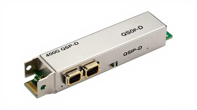
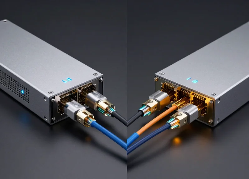
The successful deployment of a 400G leaf-spine topology depends on the selection of the correct optical form factor—QSFP-DD or OSFP—to facilitate high-speed interconnects between leaf and spine switches. While both standards support 400Gbps throughput using eight lanes of 50Gbps PAM4 signaling, they diverge significantly in mechanical design, thermal management, and backward compatibility paths, influencing long-term fabric scalability.
QSFP-DD: Density and Legacy Integration
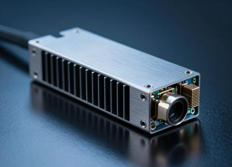
QSFP-DD (Quad Small Form-factor Pluggable Double Density) is currently the most widely adopted 400G interface due to its backward compatibility with existing QSFP infrastructure. By adding a second row of electrical contacts, the design doubles the number of high-speed lanes from four to eight while maintaining the original QSFP footprint. This allows data center operators to populate new 400G switches with older 100G (QSFP28) or 40G (QSFP+) modules, protecting previous hardware investments during a phased migration to 400G.
OSFP: Thermal Excellence for Future Scaling
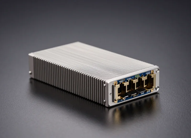
OSFP (Octal Small Form-factor Pluggable) was engineered from the ground up to address the thermal challenges of high-density optical networking. It is physically larger than the QSFP-DD and features integrated heat-sink fins directly on the module casing. While it requires a mechanical adapter for backward compatibility with QSFP transceivers, its superior heat dissipation—supporting power envelopes up to 15W and beyond—makes it a preferred choice for 800G-ready spine switches and high-power coherent optics used in data center interconnects (DCI).
| Feature | QSFP-DD | OSFP |
|---|---|---|
| Electrical Lanes | 8 Lanes (50G PAM4) | 8 Lanes (50G PAM4) |
| Backward Compatibility | Native (QSFP+/QSFP28) | Via Mechanical Adapter |
| Thermal Capacity | Approx. 7W - 12W | Approx. 12W - 15W+ |
| Module Width | 18.35 mm | 22.58 mm |
| Ideal Use Case | High-density Leaf Switches | Thermal-intensive Spine Switches |
Critical Implementation Considerations
When building a 400G fabric, the choice between these form factors is often dictated by the switch silicon and the vendor's chassis design. For leaf-to-spine links, engineers must ensure that the breakout capabilities of the chosen form factor match the required port radix. For example, a 32-port 400G OSFP spine switch offers different airflow characteristics than a 32-port QSFP-DD switch, which can impact the overall cooling strategy of the rack.
- Is QSFP-DD compatible with OSFP?
No, they are mechanically different. Interoperability is only possible at the fiber level using standardized optical specs like 400G-DR4 or 400G-FR4, provided both ends use compatible LC or MPO connectors. - Why is thermal management so important in 400G?
400G transceivers consume significantly more power than 100G modules; if heat is not managed, it leads to signal degradation, increased bit error rates (BER), and shortened hardware lifespan. - Which form factor is better for 800G upgrades?
While both have 800G versions, OSFP's larger surface area and integrated cooling give it a technical advantage for the higher power demands of next-generation 800G and 1.6T optics.
Cabling Strategies for 400G Interconnects
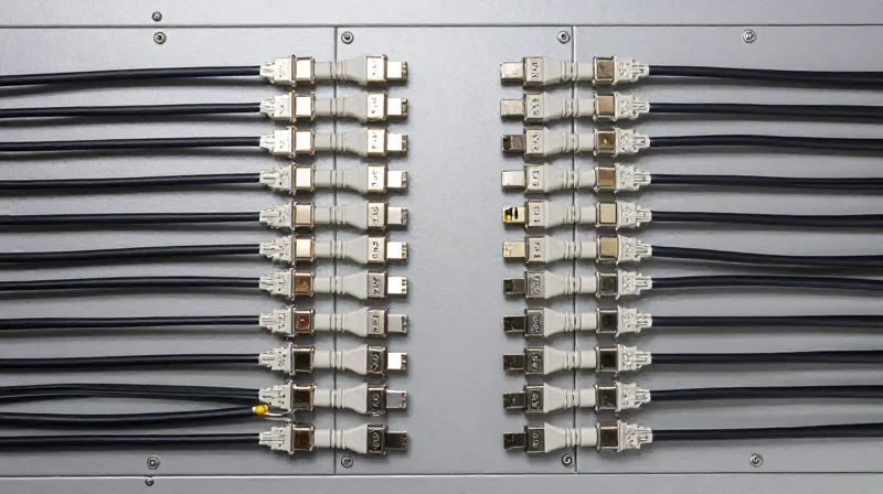
Optimizing 400G Connectivity: Cables and Fibers
400G interconnects demand a nuanced approach to physical layer infrastructure where passive copper Direct Attach Cables (DACs) serve ultra-short rack distances, while Active Optical Cables (AOCs) and single-mode or multi-mode fiber transceivers bridge the gap for inter-rack and spine-to-leaf connections. Because 400G utilizes PAM4 (Pulse Amplitude Modulation 4-level) signaling, signal integrity is significantly more sensitive to distance and interference than previous NRZ-based 100G generations, making the choice of cabling a critical factor in network stability and power efficiency.
Direct Attach Cables (DAC) and Active Optical Cables (AOC)
DACs remain the gold standard for Top-of-Rack (ToR) connectivity within the same or adjacent cabinets. They consume zero power and offer the lowest latency because they do not require signal conversion. However, due to signal integrity challenges at 400G, passive copper reach is typically limited to 2.5 meters. For reaches up to 30 meters, AOCs provide a lightweight, flexible alternative that uses active electrical-to-optical conversion. While AOCs consume more power than DACs, they are much easier to route through cable management systems and avoid the electromagnetic interference (EMI) issues associated with high-speed copper.
| Cabling Type | Typical Reach | Power Consumption | Best Use Case |
|---|---|---|---|
| Passive Copper DAC | up to 2.5m | Negligible | Intra-rack (Leaf to Server) |
| Active Optical Cable (AOC) | up to 30m | Medium (~2W per end) | Inter-rack (Adjacent Leaf-Spine) |
| Multi-mode Fiber (MMF) | up to 100m | High (~8-10W) | Data Center Row Interconnects |
| Single-mode Fiber (SMF) | up to 10km | High (~10-12W) | Campus/Long-haul Spines |
Multi-mode vs. Single-mode Fiber in 400G Fabrics
In large-scale 400G leaf-spine topologies, the choice between Multi-mode Fiber (MMF) and Single-mode Fiber (SMF) often hinges on the specific transceiver type. MMF solutions, like 400GBASE-SR8, are historically cost-effective for short spans but require complex parallel cabling (16 fibers per link). Increasingly, enterprise data centers are migrating toward Single-mode Fiber (400GBASE-DR4 or FR4). SMF supports much longer distances and provides a clearer migration path to 800G and 1.6T speeds without requiring a complete fiber plant overhaul, effectively future-proofing the infrastructure.
The Role of Breakout Cabling
Breakout cabling is a vital strategy for optimizing 400G port density. By using breakout cables (e.g., 1x400G to 4x100G or 8x50G), network architects can connect high-bandwidth spine ports to multiple lower-speed leaf switches or directly to high-performance servers. This reduces the total number of switches and transceivers required, which in turn lowers power consumption and cooling costs across the entire fabric.
Cabling Strategy FAQ
- Why is passive copper DAC reach shorter at 400G compared to 100G?
400G utilizes PAM4 modulation which is more sensitive to signal attenuation and electromagnetic interference, limiting effective copper transmission to shorter distances than the previous NRZ modulation used in 100G. - When should I choose SMF over MMF for 400G?
Choose SMF when distances exceed 100 meters or when you want to future-proof the facility for speeds beyond 400G, as SMF offers higher bandwidth potential and significantly lower signal loss. - Are AOCs better than transceivers with separate cables?
AOCs are more convenient and cost-effective for fixed-length connections where you do not expect to change the fiber, but separate transceivers offer more flexibility for cable routing, easier troubleshooting, and field replacement.
Routing and Load Balancing with ECMP
Routing and Load Balancing with ECMP
In a 400G leaf-spine topology, Equal-Cost Multi-Path (ECMP) routing is the mechanism that transforms redundant physical connections into a high-performance, non-blocking fabric. Unlike traditional hierarchical designs that rely on blocking redundant paths to prevent loops, ECMP allows every link between the leaf and spine layers to carry traffic simultaneously. By using Layer 3 routing protocols—most commonly BGP (Border Gateway Protocol)—the network identifies multiple paths with the same cost to a destination, enabling a deterministic distribution of 400G flows across the entire available bandwidth of the spine.
The Mechanics of Hashing and Path Selection
To maintain packet ordering while maximizing throughput, 400G switches employ sophisticated hashing algorithms. The switch examines specific fields in the packet header, typically a '5-tuple' consisting of the Source IP, Destination IP, Source Port, Destination Port, and Protocol. This hash value determines which specific spine-bound link a flow will follow. In 400G environments, ensuring high entropy in these hashes is critical to prevent 'polarization,' where traffic inadvertently clusters on a single link while others remain underutilized.
| Feature | Traditional STP (Layer 2) | ECMP (Layer 3 Leaf-Spine) |
|---|---|---|
| Link Utilization | Passive/Blocked (Active-Standby) | Active-Active (All links used) |
| Convergence Speed | Slow (Seconds) | Sub-second (Milliseconds) |
| Bandwidth Scaling | Limited by single link speed | Horizontal scaling across multiple spines |
| Traffic Steering | Static path based on topology | Flow-based load balancing |
Key Advantages of ECMP in 400G Fabric
- Predictable Latency
Since every spine is exactly one hop away from any leaf, ECMP ensures that traffic follows the shortest path, providing consistent and low latency for East-West traffic. - Massive Throughput Aggregation
By distributing traffic across up to 64 or 128 paths (depending on the switch ASIC), ECMP allows the network to aggregate multiple 400G links into a multi-terabit fabric. - Fault Tolerance
If a spine switch or a 400G link fails, the routing protocol removes that path from the ECMP group, and traffic is instantly redistributed among the remaining healthy links without a total network reconvergence.
Challenges: Elephant Flows and Entropy
While ECMP is highly effective for a large number of small flows (mice flows), it can encounter challenges with 'elephant flows'—single, massive data transfers that saturate one 400G link while others are idle. Modern 400G data centers mitigate this through flowlet switching or adaptive routing, which can dynamically reassign portions of a flow to less congested paths within the fabric, further refining the load-balancing capabilities provided by standard ECMP.
ECMP Implementation FAQ
- Which routing protocols support ECMP?
OSPF and IS-IS support it, but BGP (specifically eBGP) is the industry standard for 400G leaf-spine due to its scalability and policy control. - Does ECMP cause packet reordering issues?
Standard ECMP keeps all packets of a single flow on the same path to prevent reordering. Advanced 'packet-spraying' techniques require hardware-level reassembly support. - What is 'Maximum Paths' in ECMP configuration?
It refers to the number of equal-cost routes a switch can install in its routing table. For 400G fabrics, switches often support 32 to 128 paths.
Scalability and Future-Proofing for 800G
Scalability and Future-Proofing for 800G
400G leaf-spine topology serves as a critical bridge between legacy 100G infrastructures and the emerging 800G standard, utilizing a scale-out architecture that decouples physical capacity from logical routing. Because the fabric is non-blocking and uses uniform latency paths, upgrading to 800G primarily involves swapping out modular components—such as line cards or transceivers—and leveraging the latest generation of switch silicon (e.g., Broadcom Tomahawk 5) without needing to redesign the cabling plant or core topology logic.
Technological Evolution: From 400G to 800G
The transition to 800G is driven by the evolution of SerDes (Serializer/Deserializer) technology, moving from 56G PAM4 to 112G and eventually 224G PAM4. By deploying 400G systems built on 112G SerDes today, data centers align their electrical lanes with the requirements of 800G optics. This allows for 'pay-as-you-grow' scaling where additional spine switches can be added to the fabric to increase total bandwidth linearly.
| Feature | 400G Implementation | 800G/1.6T Outlook |
|---|---|---|
| SerDes Speed | 56G or 112G PAM4 | 112G or 224G PAM4 |
| Standard Form Factor | QSFP-DD / OSFP | OSFP800 / QSFP-DD800 |
| Fiber Interface | 8-lane or 4-lane | 8-lane (100G/lane) or 4-lane (200G/lane) |
| Switch Throughput | 12.8T to 25.6T | 51.2T and beyond |
Strategic Investment Protection
Future-proofing a 400G leaf-spine deployment requires focusing on the physical layer and transceiver choice. Organizations opting for OSFP (Octal Small Form-factor Pluggable) for their 400G interconnects are often better positioned for 800G due to the superior thermal management capabilities of the OSFP housing, which is designed to dissipate the higher heat generated by 800G and 1.6T DSPs.
Common Questions on 800G Migration
- Will existing fiber support 800G?
Yes, Singlemode fiber (SMF) deployed for 400G (specifically G.652) will support 800G, though distances may vary depending on whether the architecture uses DR8 or FR8 transceiver standards. - Can 400G and 800G coexist in the same spine?
Absolutely. High-radix switches support breakout configurations and mixed-speed ports (via adapter cables or multi-rate ports), allowing for a gradual phase-in of 800G leaf nodes as traffic demands increase. - Is a complete forklift upgrade necessary for 800G?
No. The leaf-spine model is designed for incremental upgrades. You can upgrade individual spines to 800G-capable hardware while maintaining 400G leaf connections, then upgrade leaves as needed.
Real-World Applications: AI, HPC, and Hyperscale Clouds

Real-World Applications: AI, HPC, and Hyperscale Clouds
The transition to 400G leaf-spine topology is driven by the necessity to eliminate bandwidth bottlenecks in environments where East-West traffic dominates and microsecond latencies determine success. This architecture provides a non-blocking, predictable fabric that allows data centers to scale linearly while maintaining the high-density interconnects required for modern, data-intensive processing.
Artificial Intelligence and Machine Learning (AI/ML)
In AI training clusters, thousands of GPUs must communicate simultaneously to process massive datasets. 400G leaf-spine networks facilitate the high-speed synchronization of gradients and model parameters. By using 400G fabrics, organizations can significantly reduce 'tail latency,' ensuring that the slowest node in a distributed training job does not stall the entire compute cluster, thereby maximizing expensive GPU utilization.
High-Performance Computing (HPC)
Modern HPC environments, used for weather forecasting, genomic sequencing, and financial modeling, rely on the low-latency characteristics of leaf-spine designs. The flat, two-tier structure minimizes the number of hops between compute nodes. When combined with RDMA over Converged Ethernet (RoCE v2) at 400G speeds, the network provides the near-line-rate performance essential for complex simulations that require frequent inter-node communication.
Hyperscale Cloud Infrastructure
Hyperscale providers utilize 400G leaf-spine to support multi-tenant isolation and massive virtualization. The 400G backbone allows these providers to consolidate smaller 10G/25G/100G links into high-speed uplinks, simplifying cable management and reducing the power-per-bit ratio. This efficiency is vital for maintaining the global availability zones that power the modern digital economy.
| Workload Type | Primary Network Driver | Typical Protocol Focus |
|---|---|---|
| AI/ML Training | Ultra-High Bandwidth / Low Jitter | RoCE v2, GPUDirect |
| HPC Simulations | Minimal Latency / Non-blocking | InfiniBand or Ethernet RDMA |
| Hyperscale Cloud | Scalability / Multi-tenancy | VXLAN, EVPN, BGP |
| Big Data Analytics | Aggregate Throughput | TCP/IP Optimizations |
Application Implementation FAQ
- Why is 400G preferred over multiple 100G links for AI?
400G reduces the complexity of Link Aggregation Groups (LAG) and ECMP pathing, providing a single high-capacity 'pipe' that reduces hashing overhead and packet reordering issues during massive data transfers. - Does 400G leaf-spine require specific cabling for HPC?
Yes, most HPC 400G deployments use Active Optical Cables (AOCs) or Single-Mode Fiber (SMF) with OSFP/QSFP-DD transceivers to maintain signal integrity over the distances required in large-scale clusters. - How does leaf-spine benefit cloud multi-tenancy?
The predictable hop count ensures that latency is consistent regardless of which physical rack a virtual machine resides in, enabling more flexible workload placement across the data center.
Transitioning to a 400G leaf-spine topology is no longer just an option for growing enterprises—it is a strategic necessity to handle the data demands of the next decade. By optimizing your architecture with the right transceivers and switching fabric, you can ensure low latency and high reliability for your most demanding applications. Ready to upgrade your network infrastructure? Contact our engineering team today for a comprehensive 400G migration assessment.