As data centers face an insatiable demand for bandwidth, the transition from 100G to 200G and 400G has become a strategic necessity. The 200G QSFP56 SR4 stands as a critical milestone in this evolution, utilizing PAM4 signaling to double throughput within the familiar QSFP form factor. However, choosing between QSFP56 and its alternatives—such as QSFP-DD or skipping directly to 400G—requires a deep dive into latency, power efficiency, and Total Cost of Ownership (TCO). This guide provides a veteran's perspective on where the QSFP56 SR4 fits in today's high-performance computing (HPC) and cloud environments.
The Rise of 200G QSFP56 SR4: Architecture and Standards

The rise of 200G QSFP56 SR4 is a direct response to the bandwidth crunch in hyperscale data centers, offering a strategic path to double network capacity without doubling the physical infrastructure. By transitioning from traditional NRZ signaling to sophisticated PAM4 (Pulse Amplitude Modulation 4-level) technology, the QSFP56 SR4 delivers 200Gbps throughput over four lanes, providing a high-density, cost-effective bridge between 100G legacy systems and 400G future-proofing.
The Shift from NRZ to PAM4 Signaling
The most fundamental change in the 200G QSFP56 architecture is the adoption of PAM4 signaling. Unlike Non-Return-to-Zero (NRZ), which carries a single bit per signal symbol, PAM4 carries two bits per symbol. This allows the module to maintain a 26.5625 GBaud rate while effectively achieving a 50Gbps data rate per lane. By aggregating four of these 50G lanes, the SR4 module achieves its 200G total bandwidth, effectively bypassing the physical limitations that would have required doubling the fiber count or the clock speed under NRZ.
Comparative Architecture: QSFP28 vs. QSFP56
| Feature | QSFP28 SR4 | QSFP56 SR4 |
|---|---|---|
| Signal Modulation | NRZ | PAM4 |
| Max Data Rate | 100 Gbps | 200 Gbps |
| Lanes x Speed | 4 x 25G | 4 x 50G |
| Typical Power Consumption | 2.5W - 3.5W | 5W - 5.5W |
| Reach (OM4 Fiber) | 100m | 100m |
Thermal Management and Form Factor Integrity
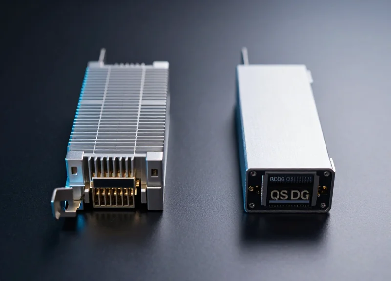
While the QSFP56 maintains the same mechanical dimensions as the QSFP28 to ensure cage compatibility, the internal architecture is significantly more complex. The inclusion of a Digital Signal Processor (DSP) to manage PAM4 signals increases power density. Engineers have optimized the QSFP56 housing and internal component layout to enhance thermal dissipation, ensuring that the module operates within safe temperature thresholds even as it consumes approximately 2W more than its 100G predecessor.
Architecture and Compatibility Insights
- Is QSFP56 SR4 compatible with legacy MPO cables?
Yes, it uses the standard MPO-12 connector, allowing data centers to reuse existing multi-mode fiber cabling (OM3/OM4/OM5). - Why skip 200G NRZ?
A 200G NRZ solution would require 8 lanes (QSFP-DD), which increases optical complexity and costs compared to the 4-lane QSFP56 PAM4 approach. - What standard governs the 200G SR4?
The specification is primarily defined under IEEE 802.3cd, ensuring multi-vendor interoperability for short-reach applications.
Latency Benchmarking: PAM4 vs. NRZ Alternatives
The transition from 25G NRZ to 50G PAM4 signaling in 200G QSFP56 SR4 modules introduces a deterministic latency overhead primarily due to the requirement for KP4 Forward Error Correction (FEC). While legacy NRZ-based 100G QSFP28 links can often operate without FEC or with low-latency Firecode FEC, the reduced Signal-to-Noise Ratio (SNR) inherent in PAM4's four-level signaling necessitates robust error correction, typically adding 100ns to 150ns of processing delay per hop.
Signal Modulation and Latency Profiles
In NRZ (Non-Return to Zero) systems, a single bit is transmitted per clock cycle using two voltage levels. In contrast, PAM4 (Pulse Amplitude Modulation 4-level) packs two bits into a single symbol by using four distinct signal levels. While this doubles the data rate without increasing the required bandwidth, the 'eye' height in a PAM4 signal is only one-third that of an NRZ signal. This sensitivity makes PAM4 highly susceptible to bit errors, necessitating the use of the IEEE 802.3bj/cd standard's Reed-Solomon (RS) FEC.
| Feature | 100G QSFP28 (NRZ) | 200G QSFP56 (PAM4) | Latency Impact |
|---|---|---|---|
| Modulation | NRZ (2-level) | PAM4 (4-level) | PAM4 requires FEC |
| FEC Type | None or RS-FEC (528, 514) | KP4 RS-FEC (544, 514) | KP4 adds ~100ns+ |
| Error Tolerance | High SNR | Low SNR | High correction needed |
| Application | HFT / Ultra-low Latency | HPC / Cloud DC | Deterministic delay |
The Role of KP4 FEC in 200G Links
The use of RS(544, 514) FEC, commonly known as KP4 FEC, is non-negotiable for 200G QSFP56 SR4 performance. This algorithm processes data in blocks, and the time required to buffer these blocks for parity checks creates a 'latency floor.' For High-Frequency Trading (HFT) or specific High-Performance Computing (HPC) clusters, this 100-150ns delay can be significant. However, for general enterprise and cloud data centers, the trade-off is widely accepted to achieve the 200G throughput required for AI/ML workloads.
- Can FEC be disabled on 200G QSFP56 SR4 to reduce latency?
Generally, no. Because PAM4 signaling has a much higher raw Bit Error Rate (BER) than NRZ, the link will typically fail to stay up or will suffer from massive packet loss without FEC enabled. - How does 200G latency compare to stacking multiple 100G NRZ links?
A single 200G QSFP56 link has higher per-port latency than a 100G NRZ link due to FEC, but it offers better aggregate throughput and lower architectural complexity than trunking multiple 100G links. - Does the switch silicon affect the PAM4 latency?
Yes. The total latency is a sum of the transceiver's electrical-to-optical conversion, the fiber propagation, and the switch ASIC's FEC engine processing time.
Power Consumption Comparison: Efficiency at the Rack Level

The 200G QSFP56 SR4 transceiver represents a critical tipping point in data center energy efficiency, offering a 25% reduction in power consumption per gigabit compared to legacy 100G QSFP28 SR4 modules. While a single 200G QSFP56 module typically draws 5W—roughly 1.5W more than its 100G predecessor—it effectively doubles the bandwidth within the same physical footprint. This allows network architects to consolidate rack space and reduce the total number of active transceivers required to achieve the same throughput, leading to lower aggregate power draw and simplified cooling requirements at the rack level.
Efficiency Metrics: Power per Gigabit Comparison
| Module Type | Typical Power (W) | Bandwidth (Gbps) | Efficiency (mW/Gbps) |
|---|---|---|---|
| 100G QSFP28 SR4 | 3.5W | 100 | 35.0 mW |
| 200G QSFP56 SR4 | 5.0W | 200 | 25.0 mW |
| 400G QSFP-DD SR8 | 12.0W | 400 | 30.0 mW |
| 2x 200G QSFP56 | 10.0W | 400 | 25.0 mW |
Thermal Stability and Rack-Level Economics
Maintaining a 5W thermal envelope is a strategic advantage for the QSFP56 form factor. Most existing air-cooled switch architectures are designed to handle 3.5W to 6W per port. By staying within this range, 200G QSFP56 SR4 modules avoid the 'thermal runaway' risks often associated with early-generation 400G QSFP-DD modules, which can exceed 12W and require exotic cooling solutions or significantly increased fan speeds. For high-density leaf-spine architectures, utilizing 200G modules allows for maximum port density without upgrading the facility's power delivery or HVAC infrastructure.
The DSP and PAM4 Factor
The primary driver behind the 5W profile is the integration of high-performance Digital Signal Processing (DSP) required for 50G PAM4 signaling. While PAM4 is more power-intensive than the NRZ signaling used in 100G, the transition to 7nm and 5nm DSP chipsets in 200G optics has mitigated this increase. Consequently, the QSFP56 SR4 provides a sweet spot where the power overhead of the DSP is offset by the massive gains in data throughput.
Efficiency FAQ
- Does 200G QSFP56 SR4 require special cooling?
No, it is designed to operate within standard air-cooled environments. Its 5W profile is compatible with most legacy 100G switch chassis that support QSFP56 upgrades. - How does the power efficiency compare to 400G?
Currently, a pair of 200G QSFP56 modules (10W total) is often more energy-efficient for 400G of throughput than a single first-generation 400G QSFP-DD module (12W+), depending on the DSP generation. - What is the impact of FEC on power consumption?
Forward Error Correction (FEC) is performed by the host switch ASIC, not the module itself. However, the module's DSP must be robust enough to maintain a low pre-FEC bit error rate, which is factored into its 5W rating.
200G QSFP56 vs. 200G QSFP-DD: Form Factor Wars
The choice between 200G QSFP56 and 200G QSFP-DD is essentially a choice between optimized specialization and forward-looking density; while the QSFP56 utilizes four 50G PAM4 lanes to minimize power consumption and heat, the QSFP-DD (Double Density) employs eight lanes to provide a seamless mechanical pathway to 400G and 800G infrastructures. Most enterprise and tier-2 providers favor the QSFP56 for its lower cooling requirements and compatibility with existing QSFP slots, whereas hyperscalers often deploy QSFP-DD even at 200G to maintain a unified hardware footprint for future capacity upgrades.
Architectural Divergence: 4-Lane vs. 8-Lane Efficiency
The QSFP56 (Quad Small Form-factor Pluggable 56) is the direct successor to QSFP28, maintaining the four-lane electrical interface but upgrading the modulation from NRZ to 50G PAM4. In contrast, the QSFP-DD introduces a second row of electrical pins to double the lane count to eight. When running at 200G, the QSFP-DD can operate either as 8x25G or 4x50G (with four lanes idle or specialized mapping), which introduces additional complexity in the internal gearbox and electrical routing compared to the native 4-lane design of the QSFP56.
| Feature | 200G QSFP56 | 200G QSFP-DD |
|---|---|---|
| Electrical Lanes | 4 x 50G PAM4 | 8 x 25G NRZ or 4x50G PAM4 |
| Power Consumption | Typical 4.5W - 5.5W | Typical 5.5W - 7.5W |
| Thermal Management | Optimized for 200G Airflow | Higher Density, Complex Cooling |
| Backward Compatibility | QSFP+, QSFP28 | QSFP+, QSFP28, QSFP56 |
| Primary Use Case | High-Efficiency 200G Fabric | 400G/800G Future-Proofing |
Thermal Stability and Cooling Constraints
From a thermal perspective, the QSFP56 SR4 holds a significant advantage for high-density rack deployments. Because it uses fewer electrical components to achieve the same 200G throughput, it generates less waste heat. QSFP-DD modules, due to their denser pin configuration and the potential for 8-lane operation, require more sophisticated cooling solutions. In environments where airflow is constrained, or where 'green' energy targets are aggressive, the QSFP56’s lower thermal profile translates to lower OpEx via reduced fan speeds and cooling system power draw.
Strategic Implementation FAQ
- Can I plug a QSFP56 module into a QSFP-DD port?
Yes, QSFP-DD ports are designed to be backward compatible with QSFP56, QSFP28, and QSFP+ modules, allowing for a mixed-speed environment. - Why choose 200G QSFP-DD if it consumes more power?
Operators choose it primarily for investment protection. If the switch hardware is already QSFP-DD based to support future 400G upgrades, using 200G QSFP-DD transceivers simplifies the sparing and management of the physical layer. - Does the 4-lane vs. 8-lane difference affect latency?
The latency difference is negligible at the physical layer; however, the choice of FEC (Forward Error Correction) required for PAM4 on both form factors is a much larger contributor to total link latency.
Ultimately, the 'Form Factor War' is less about performance parity and more about alignment with the lifecycle of the switching hardware. For dedicated 200G networks, the QSFP56 SR4 remains the performance-per-watt leader. For bridge deployments transitioning to 400G, the QSFP-DD is the pragmatic, albeit more power-intensive, choice.
The Economic Argument: Total Cost of Ownership (TCO) Breakdown
The economic argument for 200G QSFP56 SR4 rests on its ability to provide a cost-effective bridge between 100G and 400G architectures, offering a lower Total Cost of Ownership (TCO) for data centers that prioritize immediate bandwidth density without the massive infrastructure overhaul required for 400G. While initial CAPEX for QSFP56 is competitive, the true value emerges when accounting for the reduced power density and the preservation of existing MPO-12 cabling investments.
CAPEX: Acquisition and Infrastructure Integration
Initial capital expenditure (CAPEX) for 200G QSFP56 SR4 is generally lower than its 8-lane QSFP-DD counterparts. This price advantage stems from the simplified internal architecture of a 4-lane PAM4 design, which requires fewer lasers and lower component complexity. Furthermore, because it utilizes the standard MPO-12 connector, it allows operators to reuse existing fiber plants that served 40G or 100G SR4 optics, significantly reducing the cost of new cabling deployments.
| Metric | 200G QSFP56 SR4 | 200G QSFP-DD SR8 | 400G QSFP-DD SR8 |
|---|---|---|---|
| Relative Module Cost | Baseline (1x) | 1.2x - 1.4x | 2.0x - 2.5x |
| Cabling Compatibility | MPO-12 (Backward) | MPO-16 (New) | MPO-16 (New) |
| Switch Port Cost | Moderate | High | Very High |
OPEX: Power Efficiency and Thermal Management
Operational expenses are dominated by power consumption and the subsequent cooling requirements. A 200G QSFP56 SR4 module typically draws approximately 5W. In a high-density switch with 32 or 48 ports, this translates to significant energy savings over 8-lane alternatives that may require more complex cooling solutions. Over a 5-year lifecycle, the lower thermal footprint reduces the strain on data center HVAC systems, further lowering the effective TCO per gigabit by minimizing the electricity bill for both the optics and the environmental control systems.
Lifecycle and Maintenance Considerations
Reliability is a critical factor in the TCO equation. The 4-lane design of the QSFP56 SR4 reduces the potential points of failure compared to 8-lane 200G solutions. Lower complexity often correlates with higher Mean Time Between Failures (MTBF), reducing the frequency of maintenance windows and the labor costs associated with replacing failed optics in a production environment.
- Is 200G QSFP56 SR4 the most cost-effective for short-reach applications?
Yes, for distances under 100 meters using OM4 fiber, it offers the most efficient balance of cost-per-port and power consumption currently available on the market. - When does 400G become more economical than 200G?
400G becomes more economical only in hyperscale deployments where the extreme volume of traffic can justify the higher upfront hardware cost and the need for new MPO-16 fiber infrastructure. - How does FEC impact the long-term cost?
The requirement for KP4 FEC in 200G PAM4 optics ensures high link reliability, which reduces costly packet retransmissions and helps maintain consistent application performance, indirectly lowering operational costs.
Cabling Infrastructure: MPO/MTP and the Cost of Fiber
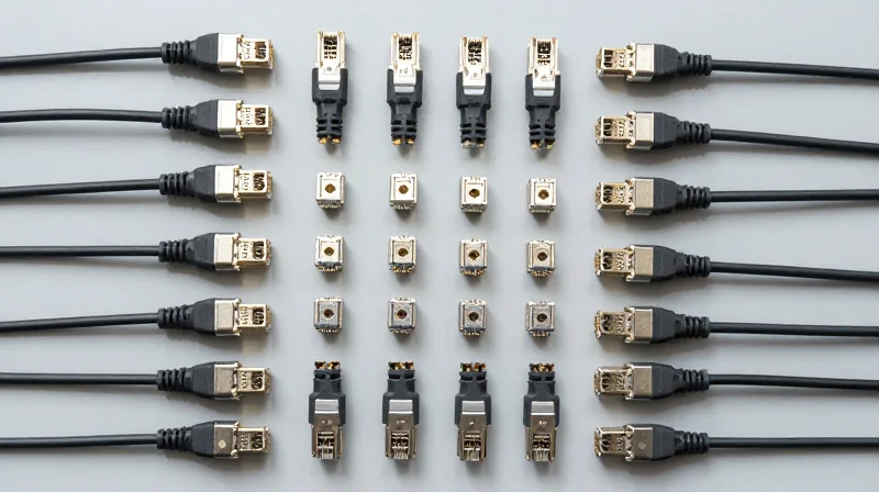
The Infrastructure Backbone: MPO/MTP and Parallel Multi-mode Fiber
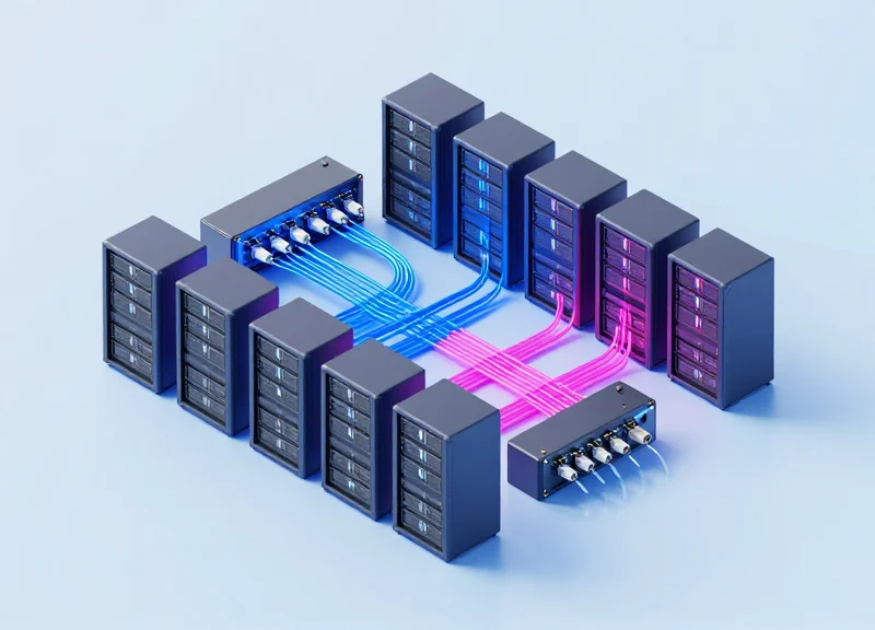
The 200G QSFP56 SR4 transceiver achieves its high-speed throughput by distributing data across eight parallel fibers—four lanes for transmission and four for reception—standardized on MPO-12 or MTP-12 connectors. This parallel architecture is a direct evolution of the 40G and 100G SR4 standards, allowing network operators to leverage their existing multi-mode fiber (MMF) plants without the need for the complex optical multiplexing required by single-mode alternatives. By using a physical-layer split for data lanes, SR4 optics remain significantly cheaper to produce than duplex single-mode optics, though this shift places a greater emphasis on the quality and density of the structured cabling system.
Comparative Performance Across Fiber Grades
| Fiber Type | Effective Modal Bandwidth (EMB) | 200G SR4 Max Distance | Relative Cabling Cost |
|---|---|---|---|
| OM3 | 2000 MHz·km | 70 Meters | Lowest |
| OM4 | 4700 MHz·km | 100 Meters | Moderate |
| OM5 | 28000 MHz·km (at 850nm) | 100 Meters+ | Highest |
While OM3 and OM4 are the most prevalent fiber types in legacy data centers, 200G SR4 pushes the limits of their modal bandwidth. OM4 is widely considered the baseline for 200G deployments, providing the necessary 100-meter reach for standard Top-of-Rack (ToR) to Spine connections. OM5, though more expensive, offers Wideband Multimode Fiber (WBMMF) capabilities that support Shortwave Wavelength Division Multiplexing (SWDM). However, for a pure SR4 parallel link, OM5 provides similar distance limitations to OM4, making the extra investment in OM5 a strategic choice for future-proofing rather than an immediate requirement for 200G performance.
TCO Analysis: Cabling vs. Optics
The total cost of ownership (TCO) for a 200G network must account for the inverse relationship between transceiver price and cabling complexity. SR4 transceivers are budget-friendly but require 8-fiber MPO trunks, which are more expensive and harder to manage than the 2-fiber LC duplex cables used by single-mode transceivers like 200G FR4. In high-density environments, the cost savings of SR4 optics typically outweigh the higher price of MPO cabling for distances under 100 meters, especially when considering the power savings associated with VCSEL-based multi-mode technology.
- Can I reuse 100G MPO-12 cables for 200G SR4?
Yes, 200G QSFP56 SR4 uses the same 8-fiber pinout (outer 4 fibers on each side) as 100G SR4, making the physical cabling infrastructure fully compatible. - Why choose MTP over MPO for 200G?
MTP connectors are a branded, high-performance version of MPO that offer lower insertion loss and better mechanical durability, which is vital for maintaining the strict link budgets of PAM4-modulated 200G signals. - When should I switch from SR4 (Multi-mode) to FR4 (Single-mode)?
The transition point is generally at the 100-meter mark. Beyond 100 meters, the signal degradation on OM4 fiber becomes too high for SR4, necessitating a move to single-mode fiber and the more expensive FR4 optics.
Application Scenarios: AI, HPC, and Enterprise Cloud

The 200G QSFP56 SR4 outperforms alternatives by providing a 100% bandwidth increase over legacy 100G SR4 modules while utilizing the same 4-lane architecture, allowing for seamless upgrades in environments where 400G port density is physically or thermally constrained. By leveraging existing MPO-12 cabling, it offers the most cost-effective path for doubling network capacity in short-reach data center applications without the significant CAPEX associated with 400G optics or the power-hungry 8-lane QSFP-DD designs.
AI Training Clusters and GPU-to-GPU Interconnects
In modern AI and Machine Learning (ML) workloads, the demand for low-latency, high-bandwidth communication between GPUs is paramount. 200G QSFP56 SR4 is often the preferred choice for NVIDIA HDR InfiniBand and high-performance Ethernet fabrics. While 400G offers more total bandwidth, 200G modules often provide better thermal stability in densely packed server racks. This enables data centers to maintain higher port densities on the switch side, ensuring that the heavy computational demands of training large language models are met without triggering thermal throttling or exceeding power budgets.
High-Performance Computing (HPC) and Parallel Processing
High-Performance Computing environments rely on parallel processing where data must be synchronized across thousands of nodes. The 200G QSFP56 SR4 is uniquely suited for these scenarios because it matches the native 50G PAM4 electrical lane signaling used in current-generation compute nodes. This eliminates the need for complex gearboxing (converting 50G to 100G lanes), which reduces latency and hardware cost. For HPC architects, this results in a more efficient fabric that maximizes throughput-per-dollar compared to over-provisioning with 400G or remaining stuck at 100G bottlenecks.
Comparative Scenario Analysis
| Application Scenario | Preferred Optic | Primary Advantage | Economic Factor |
|---|---|---|---|
| AI Edge Clusters | 200G QSFP56 SR4 | Optimal Thermal/Power Balance | Highest Throughput-per-Watt |
| Legacy DC Upgrade | 200G QSFP56 SR4 | Cabling Reuse (MPO-12) | Lowest CAPEX for 2x Speed |
| Hyper-scale Core | 400G QSFP-DD/OSFP | Maximum Raw Bandwidth | Highest Power/Cost Density |
| Basic Storage/Web | 100G QSFP28 SR4 | Proven Stability | Lowest Unit Cost |
Enterprise Cloud and Multi-Tenant Data Centers
For enterprise cloud providers, the 200G QSFP56 SR4 provides a path to modernize internal Leaf-Spine architectures while preserving investments in OM3 and OM4 multi-mode fiber. As enterprise traffic shifts toward microservices and containerized applications, the east-west traffic demand necessitates more than 100G. However, many enterprise organizations find the 400G ecosystem's power requirements and the cost of upgrading to OM5 fiber too steep. 200G SR4 bridges this gap, offering the port density required for high-density virtualization at a fraction of the power cost per gigabit compared to early-gen 400G solutions.
Frequently Asked Questions
- Why choose 200G QSFP56 over 400G for AI workloads?
200G QSFP56 modules generate significantly less heat and consume less power than 400G modules. In high-density GPU racks where cooling is already a challenge, 200G allows for a more stable and cost-effective interconnect strategy. - Is 200G QSFP56 SR4 compatible with existing 100G cabling?
Yes, it uses the same MPO-12 connectors and 8-fiber (4 lanes) multi-mode parallel fiber as 100G SR4, making it a 'plug-and-play' upgrade for existing physical infrastructure. - When is 400G a better choice than 200G SR4?
400G is better for core-to-core backbone links where absolute bandwidth per fiber pair is more important than power consumption or individual port cost.
Interoperability and Backward Compatibility Challenges
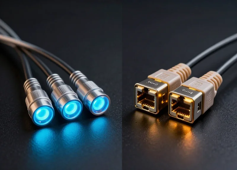
The primary challenge in deploying 200G QSFP56 SR4 lies in the fundamental shift in signal modulation; unlike the 100G QSFP28 standard which relies on Non-Return-to-Zero (NRZ), 200G QSFP56 utilizes Four-Level Pulse Amplitude Modulation (PAM4). This transition creates a hardware-level incompatibility that prevents simple 'plug-and-play' backward compatibility with 100G ports without the use of specific gearbox-equipped middle-ware or specialized breakout configurations.
The Modulation Gap: PAM4 vs. NRZ
The industry's move to 50G-per-lane signaling required PAM4 to double the data rate within the same bandwidth. While 100G QSFP28 SR4 uses four lanes of 25G NRZ, the 200G QSFP56 SR4 uses four lanes of 50G PAM4. Because the clocking and error correction requirements differ substantially, a standard 200G port cannot communicate with a 100G port unless the switch ASIC supports 'dual-mode' signaling, which is not universal across all networking hardware.
| Feature | 100G QSFP28 SR4 | 200G QSFP56 SR4 | 400G QSFP-DD SR8 |
|---|---|---|---|
| Modulation | NRZ | PAM4 | PAM4 |
| Lane Rate | 4 x 25G | 4 x 50G | 8 x 50G |
| Forward Error Correction (FEC) | Optional (RS-FEC) | Mandatory (RS-544) | Mandatory (KP4) |
| Interoperability | Native to 25G/50G NRZ | Limited to PAM4 devices | Backward compatible to 200G |
Vendor Ecosystems and MSA Compliance
While the Multi-Source Agreement (MSA) provides a baseline for mechanical and electrical specifications, proprietary 'vendor lock-in' remains a hurdle. 200G optics are particularly sensitive to Forward Error Correction (FEC) settings. Interoperability issues frequently arise when mixing optics from different manufacturers where the Host-to-Module interface might have subtle timing discrepancies or when one vendor's implementation of the RS-544 (KP4) FEC does not sync seamlessly with a legacy switch's firmware.
Common Compatibility Questions (FAQ)
- Can I plug a 100G QSFP28 SR4 transceiver into a 200G QSFP56 port?
In most cases, yes, provided the switch OS supports 'backward speed sensing.' However, the port will operate only at 100G speeds using NRZ, negating the throughput benefits of the 200G hardware. - Is 200G QSFP56 compatible with 200G QSFP-DD?
Physically, no. QSFP-DD has a different pin layout and density. However, they can interoperate over the fiber link if both use 4x50G PAM4 signaling on the same wavelengths. - How does FEC impact interoperability during a 200G transition?
200G SR4 requires mandatory FEC to maintain link integrity. If the connected legacy equipment cannot support RS-544 FEC, the link will likely fail to come up even if the physical fiber connection is perfect.
Strategies for a Seamless Transition
To mitigate interoperability risks, enterprises should adopt a 'Phased Migration' strategy. This involves upgrading the core distribution layer to 400G or 800G first, which typically offers better support for various sub-rates, including 200G. Additionally, using vendor-neutral third-party optics that have been verified across multiple switch platforms (Arista, Cisco, NVIDIA/Mellanox) can reduce the friction of mixing generations within the same rack.
While the 400G horizon is expanding, the 200G QSFP56 SR4 remains a highly efficient and cost-effective solution for many high-density data center applications today. By balancing lower power draw with high throughput, it offers a pragmatic bridge for those not yet ready for the power and cooling demands of full 400G. Are you planning your next network upgrade? Contact our technical consulting team today for a comprehensive TCO analysis and custom transceiver roadmap tailored to your specific infrastructure needs.