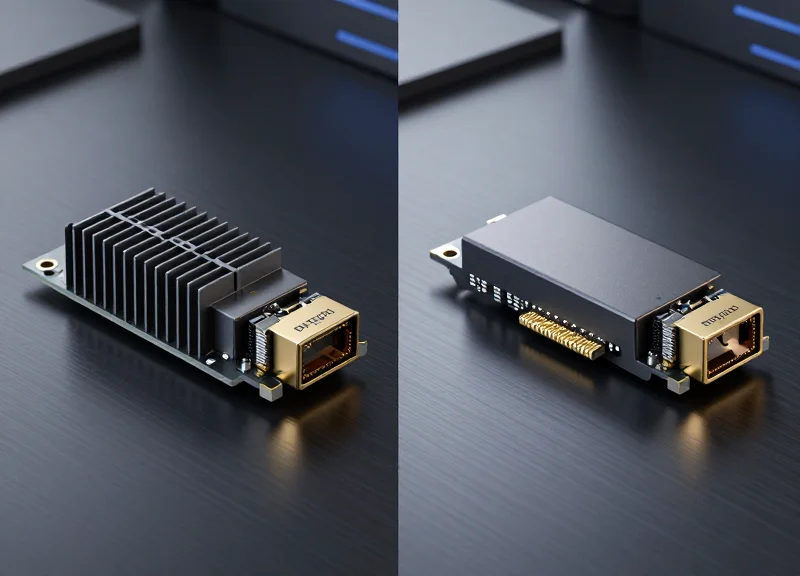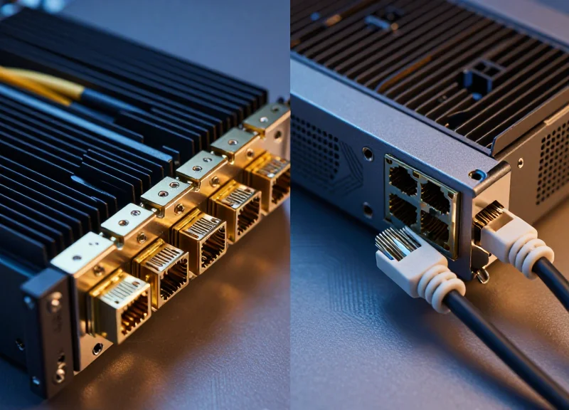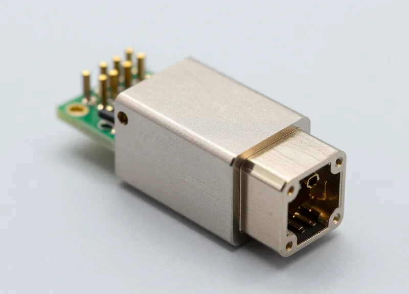
In the rapidly evolving landscape of high-speed networking, the choice of optical transceivers is as critical as the switches themselves. This guide dives deep into the world of Juniper Switch Optics, demystifying technical specifications and helping network engineers optimize their fiber infrastructure for peak performance and reliability.
The Juniper Optical Ecosystem: An Overview

Juniper switch optics constitute a sophisticated portfolio of transceivers, cables, and optical components designed to bridge the gap between high-speed silicon and physical fiber infrastructure. Within the Juniper ecosystem, these optics are the essential conduits for data, engineered to meet rigorous performance standards that define the reliability of EX, QFX, and PTX series platforms. By prioritizing tight integration with Junos OS, Juniper ensures that every optical module provides more than just a link; it provides the telemetry and stability required for modern, high-bandwidth architectures.
The Shift Toward High-Density Bandwidth
The evolution of the Juniper optical ecosystem reflects the broader industry transition from legacy 10G and 40G environments to the ultra-high-density requirements of 100G and 400G networking. Juniper's commitment to these standards is evident in their early adoption of various form factors that maximize port density without compromising thermal efficiency. This transition is not merely about speed; it involves complex signal integrity management and the use of PAM4 modulation in newer 400G modules, which Juniper integrates seamlessly into their switching fabrics.
| Form Factor | Typical Speeds | Common Use Case | Connector Types |
|---|---|---|---|
| SFP+ | 10 Gbps | Enterprise Access/Aggregation | LC Duplex |
| SFP28 | 25 Gbps | Data Center Server Access | LC Duplex |
| QSFP28 | 100 Gbps | Core/Spine-Leaf Interconnect | MPO/MTP or LC |
| QSFP-DD | 400 Gbps | Cloud-Scale Data Centers | MPO-16 or CS |
System Integration and Diagnostics
A key differentiator in the Juniper optical ecosystem is the depth of diagnostic capability provided through Digital Optical Monitoring (DOM). When a Juniper-certified optic is plugged into a switch, Junos OS can immediately access real-time data including laser bias current, optical transmit/receive power, and temperature. This allows network administrators to perform proactive maintenance and troubleshoot physical layer issues before they result in significant downtime or packet loss.
- Are Juniper optics hot-swappable?
Yes, all standard Juniper transceivers are designed for hot-insertion and hot-removal, allowing for maintenance and upgrades without powering down the host switch. - Why does Juniper prioritize specific form factors like QSFP-DD?
QSFP-DD offers backward compatibility with QSFP+ and QSFP28, providing a seamless migration path to 400G while maintaining high port density on switches like the QFX5220. - What is the role of Junos in optical management?
Junos provides the software interface for configuring breakout ports, monitoring optical health via SNMP or telemetry, and ensuring that the module operates within the specific power envelope of the hardware slot.
Evolution of Juniper Optics: From 1G to 400G

Evolution of Juniper Optics: From 1G to 400G
The evolution of Juniper switch optics reflects a strategic transition from low-speed serial links to complex, multi-lane parallel architectures designed to meet the exponential growth of global data traffic while maintaining strict thermal and power efficiency.
The Foundations: 1G and 10G SFP/SFP+
In the early iterations of the Juniper EX Series, the 1G SFP (Small Form-factor Pluggable) was the industry standard. As enterprise needs scaled, Juniper moved to the SFP+ form factor. While maintaining the same physical dimensions as the 1G SFP, SFP+ modules supported 10Gbps by offloading certain signal processing tasks to the host switch, significantly reducing the module's power consumption and cost. This era cemented the 'pluggable' philosophy, allowing network engineers to mix and match fiber types (SR, LR, ER) on a single line card.
The High-Density Shift: 40G and 100G QSFP
The leap to 40G and 100G introduced the Quad Small Form-factor Pluggable (QSFP) family. For 40G (QSFP+), Juniper utilized four parallel 10Gbps lanes. The subsequent 100G (QSFP28) standard was a breakthrough in efficiency, utilizing four 25Gbps lanes to achieve 100Gbps in the same footprint. This modularity allowed Juniper QFX Series switches to achieve the high port density required for modern leaf-spine data center architectures without increasing the physical size of the hardware.
Modern Scale: 400G QSFP-DD
Currently, Juniper is leading the transition to 400G using the QSFP-DD (Double Density) form factor. This technology features an eight-lane electrical interface, doubling the lanes of the QSFP28. By utilizing PAM4 (Pulse Amplitude Modulation) signaling, each lane operates at 50Gbps. The critical advantage of Juniper’s 400G implementation is backward compatibility; a QSFP-DD port can typically accept legacy QSFP28 and QSFP+ modules, protecting long-term hardware investments.
| Form Factor | Max Speed | Modulation | Typical Juniper Series |
|---|---|---|---|
| SFP | 1 Gbps | NRZ | EX2300, EX3400 |
| SFP+ | 10 Gbps | NRZ | EX4300, QFX5100 |
| QSFP+ | 40 Gbps | NRZ (4x10G) | QFX5110, QFX5200 |
| QSFP28 | 100 Gbps | NRZ (4x25G) | QFX5120, PTX1000 |
| QSFP-DD | 400 Gbps | PAM4 (8x50G) | QFX5220, PTX10001 |
- Is SFP+ compatible with SFP28 ports?
Yes, Juniper switches with SFP28 ports (25G) generally support 10G SFP+ modules, though the port speed must be manually configured to 10G in the Junos OS. - Can I plug a 100G QSFP28 into a 400G QSFP-DD port?
Yes, one of the primary design goals of QSFP-DD is backward compatibility with QSFP28 and QSFP+ modules, allowing for gradual network upgrades. - What is the primary benefit of PAM4 modulation in 400G?
PAM4 allows for twice the data transmission per clock cycle compared to traditional NRZ, enabling 400G speeds without requiring double the physical fiber infrastructure.
Deconstructing Form Factors: SFP, QSFP, and CFP
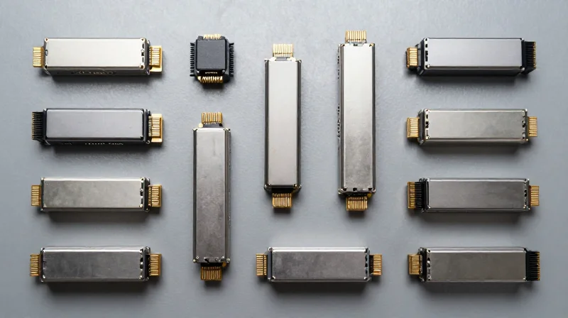
Juniper switch optics are defined by their physical form factors, which determine the port density, thermal dissipation capacity, and electrical interface configuration for various hardware lines. Selecting the correct form factor—whether it is the compact SFP for edge connectivity, the dense QSFP for data centers, or the robust CFP for core routing—is critical for ensuring hardware compatibility and optimizing the spectral efficiency of a Juniper network fabric.
SFP and SFP+: The Standards for Edge and Access
The Small Form-factor Pluggable (SFP) is the most ubiquitous interface in the Juniper EX and MX series. Standard SFP modules support 1GbE, while SFP+ modules leverage the same physical dimensions to support 10GbE and 25GbE (as SFP28). These modules utilize a 20-pin electrical connector. Because of their small footprint, Juniper can fit up to 48 SFP+ ports in a single 1U chassis, making them ideal for high-density access layer deployments.
QSFP and QSFP-DD: Driving High-Bandwidth Density
The Quad Small Form-factor Pluggable (QSFP) is the primary engine for Juniper’s QFX data center switches. By utilizing four parallel lanes, the QSFP+ form factor achieves 40GbE, while QSFP28 scales to 100GbE. The electrical interface for QSFP utilizes 38 pins. To meet the demands of 400GbE, Juniper has adopted QSFP-DD (Double Density), which adds a second row of electrical pins to support an 8-lane interface while maintaining backward compatibility with standard QSFP cages.
CFP Series: High Power for Core Networking
Unlike the smaller SFP and QSFP modules, the C Form-factor Pluggable (CFP) is significantly larger and designed for high-power optical components, such as coherent optics used in long-haul DWDM applications. Juniper utilizes CFP, CFP2, and CFP4 modules primarily in its MX Series 3D Universal Edge Routers and PTX Series Core Routers. These modules offer superior heat dissipation, allowing for complex digital signal processing (DSP) required for 100G and 400G over long distances.
Comparative Technical Specifications
| Form Factor | Typical Bandwidth | Pin Count | Juniper Hardware Series |
|---|---|---|---|
| SFP / SFP28 | 1G / 10G / 25G | 20 pins | EX Series, MX Series |
| QSFP+ / QSFP28 | 40G / 100G | 38 pins | QFX Series, PTX Series |
| QSFP-DD | 400G | 76 pins | QFX5220, PTX12000 |
| CFP2 / CFP4 | 100G / 400G | 104 / 56 pins | MX960, PTX10008 |
Form Factor Implementation FAQs
- Can I insert an SFP+ module into a QSFP28 port?
Not directly. However, Juniper supports the use of a QSA (QSFP-to-SFP Adapter) which converts a single 40G/100G port into a 10G/25G port. - What is the primary advantage of QSFP-DD over CFP2?
QSFP-DD offers much higher port density, allowing 32 to 36 ports on a single 1U switch faceplate, whereas CFP2's larger size limits density but handles higher thermal loads. - Are Juniper optics hot-swappable across all form factors?
Yes, SFP, QSFP, and CFP modules are designed to be hot-swappable, allowing for maintenance without powering down the Juniper chassis.
Technical Specifications: Wavelengths, Distances, and Media
Technical Specifications: Wavelengths, Distances, and Media
Juniper optics are engineered to leverage specific electromagnetic wavelengths to transmit data over physical media, where the choice between Multi-Mode Fiber (MMF) and Single-Mode Fiber (SMF) dictates the maximum achievable distance and the required transceiver architecture. The selection of a Juniper module is fundamentally a balance between the optical power budget, the modal bandwidth of the cable, and the spectral characteristics of the laser source, such as Vertical-Cavity Surface-Emitting Lasers (VCSEL) for short ranges or Distributed Feedback (DFB) lasers for long-haul applications.
Multi-Mode Fiber (MMF) and the 850nm Standard
Multi-mode fiber is the standard for intra-datacenter connectivity within Juniper environments. Utilizing a 50/125 micron core, these fibers allow multiple modes of light to propagate. Juniper SR (Short Reach) and SW (Short-wavelength) modules typically operate at the 850nm wavelength. While cost-effective, these links are limited by modal dispersion, meaning the signal quality degrades quickly over distance. In modern Juniper QFX deployments using OM3 or OM4 cabling, 850nm optics are generally capped at distances between 100m and 150m for 10G to 100G speeds.
Single-Mode Fiber (SMF) for Intermediate and Long Haul
For campus backbones and metropolitan area networks (MAN), Juniper utilizes Single-Mode Fiber with a much narrower 9 micron core. By allowing only a single mode of light to travel, modal dispersion is virtually eliminated, allowing for significantly higher bandwidth over longer distances. Juniper LR (Long Reach) modules operate at 1310nm to achieve 10km distances, while ER (Extended Reach) and ZR (Zephyr Reach) modules utilize the 1550nm window, where glass fiber exhibits its lowest attenuation, enabling reaches of 40km to 80km without amplification.
| Wavelength | Fiber Type | Max Reach | Juniper Module Designators |
|---|---|---|---|
| 850nm | MMF (OM3/OM4) | 100m - 150m | SR, SR4, SR10 |
| 1310nm | SMF (OS2) | 10km | LR, LR4, PLR4, DR4 |
| 1550nm | SMF (OS2) | 40km | ER, ER4 |
| 1550nm (C-Band) | SMF (OS2) | 80km | ZR, DWDM |
Common Implementation Questions
- Can I connect a Juniper SMF optic to an MMF cable?
No. The core size mismatch (9um vs 50um) causes extreme signal loss and reflection, preventing the link from coming up or resulting in high bit-error rates. - What is the significance of the 1310nm wavelength in 100G Juniper optics?
In QSFP28-LR4 modules, Juniper uses four WDM channels around 1310nm to deliver 100Gbps over a single pair of SMF, reaching up to 10km. - When should I use a 1550nm ZR module?
ZR optics are specifically for long-distance data center interconnects (DCI) or service provider transport where the span exceeds 40km but stays under 80km.
It is critical for network engineers to match the Juniper optic's optical power budget with the fiber's attenuation. For 1550nm ER and ZR modules, the high launch power can sometimes overwhelm a short-range receiver, necessitating the use of inline optical attenuators to prevent hardware damage.
Junos OS Integration: Monitoring and Diagnostics

Junos OS treats optical transceivers as intelligent components of the network fabric, leveraging Digital Optical Monitoring (DOM) to provide deep insights into physical layer performance. By integrating optical diagnostics directly into the CLI and management APIs, Juniper ensures that network administrators can monitor signal integrity, power levels, and hardware health without needing external physical testing equipment.
Harnessing Digital Optical Monitoring (DOM)
DOM is a standardized technology that allows the switch to query the optical module's internal sensors. In Junos OS, this data is surfaced through specific operational commands, allowing for real-time tracking of parameters that could indicate an impending cable failure or transceiver degradation. The integration ensures that the system can automatically log events when an optic operates outside of its calibrated specifications.
user@juniper-switch> show interfaces diagnostics optics et-0/0/0
Physical interface: et-0/0/0
  Optical diagnostics          :  Operational
    Laser bias current         :  6.120 mA
    Laser output power         :  1.2140 mW / 0.84 dBm
    Module temperature         :  34 degrees C / 93 degrees F
    Module voltage             :  3.3120 V
    Receiver signal average optical power :  0.8920 mW / -0.49 dBm
Key Diagnostic Parameters and Alarm Thresholds
Junos OS categorizes optical data into specific metrics, each with high and low 'Warning' and 'Alarm' thresholds. These thresholds are typically hardcoded into the transceiver's EEPROM by the manufacturer and read by Junos to trigger system log messages.
| Metric | Description | Typical Alarm Condition |
|---|---|---|
| RX Power | The strength of the incoming signal from the remote end. | Low power often indicates a dirty connector or fiber break. |
| TX Power | The strength of the signal being transmitted by the local module. | Low power suggests a failing laser or internal module fault. |
| Bias Current | The current required to drive the laser diode. | Drastic increases over time often signal the end-of-life for the laser. |
| Temperature | The internal operating temperature of the module. | High temperatures indicate airflow issues or chassis overheating. |
Integration with Junos Telemetry Interface (JTI)
For modern data centers, manual CLI checks are insufficient for large-scale operations. Junos OS supports streaming these optical metrics via the Junos Telemetry Interface (JTI). By using gRPC or gNMI, engineers can export DOM data to time-series databases like InfluxDB or Prometheus. This enables automated alerting and historical trend analysis, allowing teams to identify 'slow-failing' optics that might still be passing traffic but exhibit degrading signal-to-noise ratios.
Optical Monitoring FAQ
- Why is my transceiver reporting 'N/A' for diagnostics?
This usually occurs if the optical module does not support DOM or if it is a third-party module not fully compatible with the Junos I2C communication protocol. - What is the difference between 'Alarm' and 'Warning' in Junos?
A 'Warning' indicates that a parameter has drifted outside the optimal range but the link is still operational; an 'Alarm' indicates a critical state that often results in the interface being marked as 'Down'. - Can I monitor 400G optics the same way as 10G SFP+?
Yes, though 400G QSFP-DD modules provide multi-lane data, Junos aggregates these in the diagnostic output, showing power levels for each individual lane (e.g., Lane 0 through Lane 7).
The Compatibility Matrix: OEM vs. Third-Party Optics
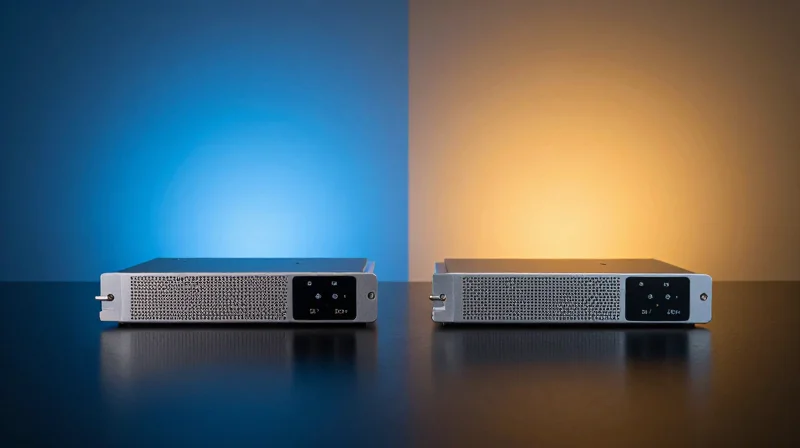
While Juniper Networks officially recommends and supports only their own branded transceivers, Junos OS provides a pathway for third-party optics integration through specific CLI overrides. The core distinction between OEM and third-party modules lies not in the physical laser hardware—which is often manufactured by the same Tier-1 foundries—but in the EEPROM coding that identifies the module to the Junos kernel and ensures 100% adherence to Juniper’s Digital Optical Monitoring (DOM) thresholds.
Unlocking Compatibility: The 'allow-unsupported-transceiver' Command
By default, Junos OS performs a 'check-sum' on the transceiver's EEPROM. If the vendor OUI does not match Juniper’s approved list, the port may be placed in a 'link down' state or generate a 'NON-JNPR' alarm. To bypass this for testing or cost-optimization, administrators can use a hidden configuration knob. Note that this command is platform-dependent; on newer ELS (Enhanced Layer 2 Software) platforms, it is often required to enable the port to pass traffic.
set chassis fpc 0 pic 0 port 0 allow-unsupported-transceiverOEM vs. Third-Party Optics: A Comparative Analysis
| Feature | Juniper OEM Optics | Third-Party (Premium) |
|---|---|---|
| Junos Integration | Native; full DOM/DDM support. | Variable; requires EEPROM coding. |
| Cost Efficiency | Premium pricing. | Significant savings (60-90% less). |
| TAC Support | Full end-to-end troubleshooting. | Limited to the switch port only. |
| Lead Times | Subject to OEM supply chains. | Typically high availability. |
Warranty and TAC Considerations
A common misconception is that using third-party optics voids the Juniper switch warranty. Under the Magnuson-Moss Warranty Act (in the US) and similar global consumer protections, a manufacturer cannot void a hardware warranty simply for using a third-party peripheral. However, the Juniper Technical Assistance Center (TAC) reserves the right to request that you replace the third-party module with an OEM equivalent if they suspect the optic is the root cause of a physical layer issue or a Junos kernel panic.
Compatibility FAQ
- Will Junos show DOM data for third-party optics?
Only if the third-party vendor has correctly emulated the Juniper-specific I2C register mappings. If not, 'show interfaces diagnostics optics' may return N/A. - Does the 'allow-unsupported' command work on all models?
It is primarily used on EX and QFX series. High-end PTX and MX routers are more restrictive regarding the power draw and thermal profiles of uncertified modules. - Can I mix OEM and third-party optics in a Virtual Chassis?
Yes, but consistency per link-aggregation group (LAG) is recommended to ensure identical latency and signal characteristics across members.
Deployment Scenarios: Data Center, Core, and Edge

Strategic Deployment Scenarios for Juniper Optics
Juniper switch optics are engineered to meet the distinct demands of modern network architectures, providing the physical layer connectivity required for high-throughput data center leaf-spine fabrics, resilient service provider cores, and diverse campus edge networks. By selecting optics based on specific distance, speed, and media requirements, engineers can optimize Juniper hardware performance for any environment.
Data Center: Leaf-Spine Architectures
In the modern data center, Juniper optics focus on maximizing density and minimizing latency. Within a leaf-spine architecture—typically powered by QFX Series switches—high-speed short-range connectivity is the priority. 100G QSFP28 and 400G QSFP-DD SR4 optics are used for high-bandwidth uplinks between leaf and spine switches. For intra-rack connections, such as server-to-leaf links, Direct Attach Copper (DAC) cables or Active Optical Cables (AOCs) are frequently employed to reduce both power consumption and cost per port.
The Network Core: Service Provider and Long-Haul Links
Core networking, involving PTX Series or MX Series platforms, necessitates optics capable of spanning massive distances without signal degradation. Juniper's long-haul portfolio includes 'ZR' and 'ER' (Extended Range) optics that utilize DWDM (Dense Wavelength Division Multiplexing) and coherent technology. These optics allow for 100G and 400G transmission over distances exceeding 80km, which is essential for interconnecting regional data centers or service provider Points of Presence (PoPs) across a metro or wide area network.
Campus and Edge: Access Layer Connectivity
The campus edge, often utilizing EX Series switches, requires a versatile mix of copper and fiber optics. Here, SFP and SFP+ modules are the primary interfaces, providing 1GbE and 10GbE connectivity for user devices and wireless access points. Long-range (LR) optics are often used for 'fiber-to-the-closet' applications where distances between buildings or floors exceed the 100-meter limit of standard Category 6a cabling.
| Scenario | Typical Platform | Primary Optics Used | Key Requirement |
|---|---|---|---|
| Data Center Fabric | QFX Series | QSFP28-SR4 / QSFP-DD | High Density & Low Latency |
| Core / Long-Haul | PTX / MX Series | 100G-LR4 / 400G-ZR | Distance & Capacity |
| Campus Access | EX Series | SFP-LX / SFP-SX / SFP-T | Cost-Efficiency & Versatility |
| Metro Ethernet | ACX Series | BiDi (Bidirectional) SFP | Fiber Optimization |
- When should I use DAC cables instead of SR4 optics?
DAC cables are ideal for short distances (under 7 meters) within the same or adjacent racks, as they are significantly cheaper and consume less power than SR4 transceivers. - What is the benefit of BiDi optics in edge deployments?
Bidirectional (BiDi) optics allow for transmission and reception over a single fiber strand, effectively doubling the capacity of existing fiber infrastructure in campus or metro environments. - Are 400G optics compatible with older Juniper chassis?
400G optics typically require the latest generation of line cards and 'DD' (Double Density) ports found on newer QFX and PTX models; they are not backwards compatible with standard QSFP28 slots.
Troubleshooting Common Optical Link Issues
Troubleshooting Common Optical Link Issues
Troubleshooting Juniper switch optics requires a systematic approach that correlates physical layer telemetry with logical interface statistics to isolate failures between the transceiver hardware, fiber plant integrity, or Junos port configuration. When a link fails to initialize or experiences intermittent drops, the primary objective is to determine if the signal loss is due to attenuation, a physical mismatch, or a logical protocol error.
Validating Optical Power and DOM Levels
Digital Optical Monitoring (DOM) is the most critical tool for diagnosing layer 1 issues. By examining the 'Receive power' and 'Transmit power' against the transceiver's rated thresholds, administrators can identify failing lasers or excessive path loss. A 'Low Alarm' on RX power typically indicates a dirty fiber connector, a failed remote SFP, or a cable break.
show interfaces diagnostics optics et-0/0/0

# Output highlights:
#  Receiver signal average optical power :  0.4571 mW / -3.40 dBm
#  Module temperature                     :  34.125 degrees C / 93.425 degrees F
#  Laser output power                     :  0.8921 mW / -0.49 dBm
Analyzing Interface Error Counters
If the link is physically up but experiencing performance degradation, you must analyze the interface extensive output. Cyclic Redundancy Check (CRC) errors and framing errors are indicators of data corruption during transit, often caused by marginal optical signals or electromagnetic interference.
| Error Metric | Typical Root Cause | Recommended Action |
|---|---|---|
| Input Errors / CRC | Dirty fiber tips or damaged patch cable | Clean all fiber endpoints with a click-cleaner. |
| Carrier Transitions | Intermittent power or loose transceiver seating | Reseat the SFP/QSFP module and check latching. |
| Symbol Errors | Clocking issues or mismatched FEC settings | Verify Forward Error Correction (FEC) parity. |
| Output Drops | Egress congestion or buffer exhaustion | Review Class of Service (CoS) and queue depth. |
Resolving FEC and Speed Mismatches
In 25G, 100G, and 400G deployments, a link often stays 'down' despite good light levels due to a Forward Error Correction (FEC) mismatch. Junos OS allows manual override of FEC modes (such as Clause 74 or Clause 91). If the local Juniper port is set to 'fec91' while the remote peer is 'fec74' or 'none', the link will never transition to the up state.
- Why does my transceiver show 'Checksum Error'?
This usually indicates the EEPROM on the transceiver is corrupted or the module is not properly coded for Juniper's I2C bus requirements. Try a different module. - How do I clear error statistics to re-test a link?
Use the command 'clear interfaces statistics' to reset counters and monitor for new increments. - The SFP is recognized but there is no RX light?
Ensure the fiber polarity is correct (TX to RX). If using a patch panel, verify the crossover hasn't been accidentally neutralized.
Power Consumption and Thermal Management
Power consumption and thermal management are no longer secondary considerations in modern networking; they are the primary constraints when deploying high-density Juniper hardware. As optical transceivers evolve from 10G SFP+ to 400G QSFP-DD, the power draw per port has increased significantly, demanding that network architects calculate total system power budgets and align airflow directions (AFI vs. AFO) to prevent thermal throttling and hardware failure.
The Evolution of Optical Power Consumption
In older 1GbE and 10GbE deployments, the power consumed by optics was often negligible compared to the switch silicon. However, with the rise of coherent optics and 400G modules, a single transceiver can now consume as much power as a small branch office router. Juniper switches must be provisioned with high-output Power Supply Units (PSUs) to handle the combined load of the ASIC and a full population of high-wattage optics.
| Optic Type | Typical Power Consumption | Max Power Class |
|---|---|---|
| SFP+ (10G SR/LR) | 1.0W - 1.5W | Class 1 |
| QSFP28 (100G LR4) | 3.5W - 4.5W | Class 4 |
| QSFP-DD (400G DR4) | 10W - 12W | Class 7 |
| QSFP-DD (400G ZR+) | 15W - 20W | Class 8 |
Airflow Direction: AFI vs. AFO
Juniper switches are typically deployed in 'Hot Aisle/Cold Aisle' configurations. To maintain the health of the optics, the airflow direction of the switch's fans and PSUs must match the data center's design. Incorrect airflow can cause hot air from the switch interior to be blown over the optics, causing them to exceed their operational temperature range (typically 0°C to 70°C for commercial grade).
- Airflow In (AFI / Back-to-Front)
Air enters from the FRU (Power Supply/Fan) side and exhausts through the Port side. Usually designated by Blue handles on Juniper hardware. - Airflow Out (AFO / Front-to-Back)
Air enters through the Port side and exhausts through the FRU side. Usually designated by Gold/Orange handles on Juniper hardware.
Thermal Throttling and Junos Protection
Junos OS monitors the temperature of each optical module via Digital Optical Monitoring (DOM). If a module crosses a high-temperature threshold, Junos may trigger alarms or, in extreme cases, shut down the specific port to protect the internal laser and the switch's PCB. For dense 400G deployments on platforms like the QFX5220, ensuring 'Airflow Out' (Front-to-Back) is often preferred to ensure fresh, cold air hits the transceivers first.
Power and Thermal FAQs
- Can I mix AFI and AFO components in the same Juniper chassis?
No. Mixing airflow directions in a single chassis will cause air recirculation, leading to immediate overheating and potential hardware damage. - Do 400G ZR+ optics require special cooling considerations?
Yes. Because they consume up to 20W, they require specific port spacing or high-velocity fan trays. Always check the Juniper Hardware Compatibility Tool for 'port restriction' notes. - How can I check the power draw of my optics in Junos?
Use the command 'show chassis power' to see overall consumption, or 'show interfaces diagnostics opt-diagnostics' to view temperature and voltage for specific modules.
Mastering Juniper Switch Optics is essential for building scalable, high-performance networks. Whether you are upgrading to 400G or optimizing your current SFP+ footprint, technical precision is key. Ready to optimize your network? Contact our engineering team today for a free compatibility assessment and ensure your fiber infrastructure is future-proof.