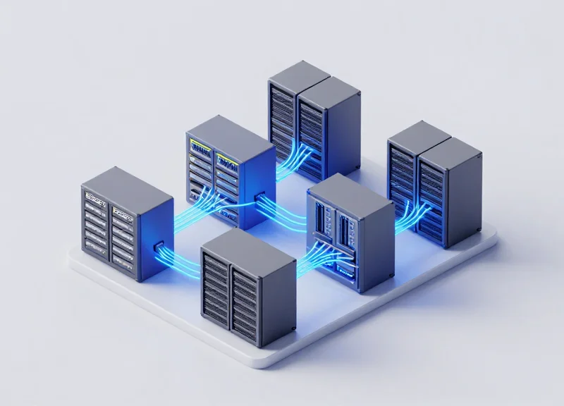
As data demands skyrocket driven by AI and cloud computing, the shift to 400G is no longer a luxury but a necessity. This guide breaks down why Leaf-Spine has become the gold standard for high-bandwidth environments and how it stacks up against legacy alternatives in real-world performance, power consumption, and long-term cost of ownership.
The Evolution of Data Center Fabrics: From 3-Tier to Leaf-Spine
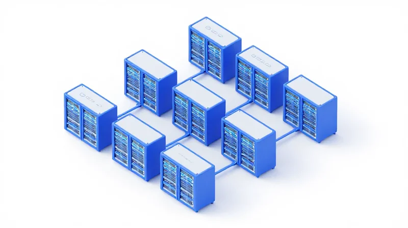
The evolution of data center fabrics is a direct response to the changing nature of data processing; where legacy three-tier architectures were built to manage external user requests, modern 400G Leaf-Spine topologies are engineered to handle the massive internal data exchanges required by distributed applications, AI training, and cloud-scale virtualization.
The Limitations of Legacy Three-Tier Architecture
For decades, the standard data center design followed a hierarchical model consisting of Access, Aggregation, and Core layers. This structure was optimized for North-South traffic—data entering or leaving the data center. However, as applications moved toward microservices and distributed storage, 'East-West' traffic (server-to-server) surged. In a three-tier model, East-West traffic must often travel 'up' to the aggregation or core layer and 'down' again, creating significant latency bottlenecks and oversubscription at the higher tiers.
| Feature | 3-Tier Architecture | Leaf-Spine Architecture |
|---|---|---|
| Primary Traffic Direction | North-South (Client-Server) | East-West (Server-Server) |
| Latency Characteristics | Variable and Higher | Deterministic and Low |
| Path Utilization | Spanning Tree (STP) blocks paths | ECMP (Active-Active) all paths |
| Scalability | Vertical (Expensive Core Upgrades) | Horizontal (Add more Leaf/Spine nodes) |
| 400G Readiness | Poor (Bottlenecks at Core) | Optimal (Fabric-wide 400G) |
The Emergence of 400G Leaf-Spine Fabrics
The Leaf-Spine (or Clos) architecture collapses the network into two tiers. Every 'Leaf' switch connects to every 'Spine' switch, ensuring that any server is only two hops away from any other server in the fabric. This flat topology is essential for 400G performance because it allows for massive parallelization through Equal-Cost Multi-Path (ECMP) routing. By utilizing 400G interconnects in this way, data centers can achieve non-blocking performance, where the network fabric itself is never the limiting factor for throughput.
- Why did the 3-tier model fail to support 400G effectively?
The 3-tier model relies on the Spanning Tree Protocol (STP) to prevent loops, which intentionally disables redundant links. In a 400G environment, wasting half the bandwidth to prevent loops is economically and operationally non-viable. - How does Leaf-Spine reduce latency in modern data centers?
By ensuring a fixed, two-hop distance between any two leaf switches, Leaf-Spine provides deterministic latency, which is critical for real-time data processing and high-frequency financial applications. - What role does 400G play in the Leaf-Spine evolution?
400G provides the necessary pipe diameter to prevent congestion as the number of leaf-to-spine connections increases, allowing the fabric to scale to thousands of ports without performance degradation.
Latency Benchmarks: Eliminating Bottlenecks in 400G Environments
In 400G environments, the primary driver for performance is the elimination of non-deterministic latency. Leaf-Spine topology achieves this by ensuring any two servers within the fabric are separated by a constant number of hops, typically providing a predictable round-trip time (RTT) that is essential for synchronized distributed computing. Unlike legacy architectures where traffic might traverse five or more switch stages, 400G Leaf-Spine reduces the path to a consistent three-stage traversal (Leaf-Spine-Leaf), minimizing signal propagation delay and jitter.
Hop Count Analysis: Leaf-Spine vs. Legacy 3-Tier
Traditional 3-tier models (Access, Aggregation, Core) were designed for North-South traffic, often resulting in 'tromboning'—a phenomenon where East-West traffic must travel up to the core and back down, accumulating significant latency. In a 400G Leaf-Spine fabric, every Leaf switch connects to every Spine switch. This creates a non-blocking architecture where the physical distance and the number of electronic conversions are minimized. At 400G speeds, the serialization delay (the time to put a packet on the wire) is reduced to approximately 30 nanoseconds for a 1500-byte packet, making the switch's internal ASIC latency and the hop count the dominant factors in the total latency budget.
| Metric | Legacy 3-Tier (10/40G) | 400G Leaf-Spine (Fabric) |
|---|---|---|
| Typical Hop Count | 5 to 7 | 2 to 3 |
| Latency Profile | Variable (Stochastic) | Fixed (Deterministic) |
| Serialization Delay | ~1.2 microseconds (10G) | ~30 nanoseconds (400G) |
| Traffic Optimization | North-South | East-West (Any-to-Any) |
Deterministic Latency for AI and HFT Workloads
For Artificial Intelligence (AI) training clusters and High-Frequency Trading (HFT) platforms, the consistency of latency (jitter) is often more critical than the absolute speed. AI workloads utilizing RDMA over Converged Ethernet (RoCE v2) require a lossless, low-latency fabric to prevent 'tail latency' from stalling distributed GPU gradients. 400G Leaf-Spine architectures utilize advanced buffer management and Explicit Congestion Notification (ECN) to maintain microsecond-level determinism even during bursty traffic patterns, ensuring that the 'All-Reduce' operations in machine learning remain efficient.
- How does 400G improve signal propagation over 100G?
While the speed of light in fiber remains constant, 400G uses PAM4 encoding and higher baud rates to transmit more data per clock cycle, significantly reducing the serialization delay compared to 100G NRZ signals. - Why is 'deterministic' latency vital for AI?
AI training involves synchronous parallel processing; if one node experiences a latency spike (jitter) due to an extra hop or congestion, the entire cluster must wait, leading to massive underutilization of expensive GPU resources. - Does physical distance between switches matter at 400G?
Yes. At 400G, even the length of the DAC cables or optical fibers contributes to the latency budget. Leaf-Spine allows for optimized physical placement within rows (ToR) to keep fiber runs short.
Power Consumption Analysis: The 400G Efficiency Paradox
The 400G efficiency paradox refers to the phenomenon where individual 400G components consume more power than their 100G predecessors, yet provide a substantial net reduction in power consumption when measured on a per-gigabit basis. By consolidating bandwidth into fewer, higher-speed lanes using PAM4 modulation and high-radix switching ASICs, data center operators can achieve a 40% to 50% improvement in energy efficiency, effectively decoupling traffic growth from power-related operational expenses.
Comparative Power Metrics: 100G vs. 400G
| Efficiency Metric | 4x 100G (QSFP28) Environment | 1x 400G (QSFP-DD) Environment |
|---|---|---|
| Aggregate Transceiver Power | ~16.0 Watts (4x 4W) | ~12.0 Watts |
| Switch Port Power (ASIC Load) | ~10.0 Watts | ~6.0 Watts |
| Total Power per 400G Bandwidth | ~26.0 Watts | ~18.0 Watts |
| Watts per Gigabit (W/Gbps) | 0.065 W/Gbps | 0.045 W/Gbps |
The Role of SerDes and ASIC Consolidation
A primary driver of this efficiency is the transition from 25G NRZ (Non-Return to Zero) signaling to 56G or 112G PAM4 (Pulse Amplitude Modulation). By doubling or quadrupling the data density per clock cycle, 400G Leaf-Spine topologies require significantly fewer physical SerDes (Serializer/Deserializer) lanes. This reduction in lane count minimizes the resistive heat loss across the PCB and simplifies the thermal management requirements for the switch chassis. Furthermore, a single 25.6Tbps ASIC in a 400G leaf switch replaces multiple 3.2Tbps or 6.4Tbps chips, consolidating the power-hungry I/O circuitry into a more efficient silicon footprint.
Environmental and Operational Impact
Beyond immediate electricity savings, the shift to 400G impacts the broader 'Green Data Center' strategy. Fewer cables and smaller physical footprints improve airflow within the rack, reducing the cooling load on CRAC units. This systemic reduction in power demand assists organizations in lowering their Power Usage Effectiveness (PUE) scores and meeting increasingly stringent ESG (Environmental, Social, and Governance) targets.
- Does 400G require more expensive cooling systems?
While 400G transceivers run hotter individually, the reduction in total hardware components and cabling density actually improves overall rack airflow, often negating the need for specialized cooling upgrades beyond standard hot/cold aisle containment. - How does the Watts-per-Gigabit metric change with 800G?
The trend continues; early 800G deployments suggest another 25-30% reduction in power per bit compared to 400G, as 112G SerDes technology matures and ASIC lithography shrinks to 5nm or 3nm. - What is the impact of DAC cables on power efficiency?
Direct Attach Copper (DAC) cables consume near-zero power compared to optical transceivers. Using 400G DACs for top-of-rack leaf-to-server connections is the most efficient way to maximize the 400G power advantage.
TCO Breakdown: Capital Expenditure vs. Operational Longevity
The Total Cost of Ownership (TCO) for 400G Leaf-Spine topologies is defined by a 'front-loaded' investment model where high initial Capital Expenditure (CapEx) for optics and high-radix switches is offset by significant reductions in Operational Expenditure (OpEx) over a three-to-five-year lifecycle. While the unit price of 400G transceivers remains higher than legacy 100G components, the massive increase in bandwidth density allows organizations to collapse their physical footprint, leading to a lower cost-per-gigabit and a more sustainable growth path for data-intensive workloads like AI and distributed cloud storage.
CapEx Analysis: The Premium of High-Density Silicon
In a 400G environment, CapEx is heavily weighted toward the cost of optics—specifically OSFP and QSFP-DD modules—and the high-radix ASIC silicon required to drive high-density ports. However, the 'hidden' CapEx savings in a Leaf-Spine model come from a reduction in the total number of chassis required. By moving to a 400G radix, a single spine switch can often replace four or more legacy 100G switches, significantly reducing the total hardware count and the associated rack space requirements.
| Metric | 400G Leaf-Spine | Legacy 100G Multi-Tier |
|---|---|---|
| Optics Unit Cost | High (Premium pricing) | Low (Commoditized) |
| Switch Density | High (Fewer units needed) | Low (Hardware sprawl) |
| Cabling Volume | Reduced (MPO-12/24 simplified) | High (Complex mesh cabling) |
| Rack Unit (RU) Usage | Optimized (1RU/2RU density) | Extensive (Multiple chassis) |
Operational Longevity: ROI via Infrastructure Consolidation
Operational longevity is where the 400G Leaf-Spine architecture excels. By reducing the number of hops and managed devices, organizations see a direct reduction in Mean Time To Repair (MTTR) and configuration complexity. Furthermore, the longevity of 400G infrastructure is secured by its compatibility with emerging 800G standards, ensuring that the physical fiber plant—especially MPO-based cabling—does not require a forklift upgrade for the next hardware generation.
Power Efficiency and Thermal Management
Legacy architectures often suffer from 'power sprawl,' where multiple low-density switches consume more aggregate energy than a consolidated 400G platform. Modern 400G switches utilize advanced 7nm or 5nm silicon, which significantly improves the performance-per-watt ratio. This translates to lower cooling requirements and reduced utility bills, which are critical for large-scale colocation or private cloud deployments where power density is at a premium.
TCO and Lifecycle FAQ
- Does 400G really lower the cost per bit over time?
Yes. While the absolute cost of hardware is higher, the four-fold increase in bandwidth means that the price paid per Gbps of capacity is lower than maintaining an equivalent bandwidth across multiple 100G links and switches. - How does Leaf-Spine impact cabling maintenance costs?
The predictable, non-blocking nature of Leaf-Spine requires fewer physical cables to achieve the same throughput as legacy three-tier networks, simplifying cable management and reducing the risk of human error during maintenance cycles. - Is the investment justified for smaller data centers?
For smaller footprints, the justification depends on growth projections. If data traffic is expected to double within 24 months, starting with 400G avoids the massive labor costs of a mid-cycle infrastructure replacement.
Leaf-Spine vs. Fat-Tree and Core-Aggregation Models
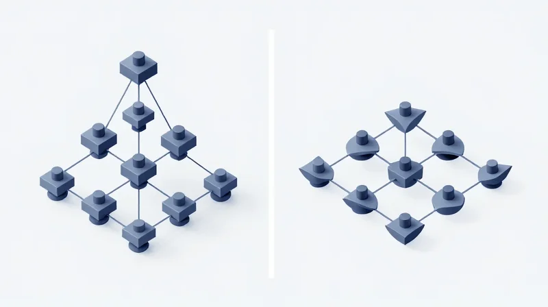
While the core-aggregation-access model served north-south client-server traffic for decades, the transition to 400G requires the low-latency, predictable performance of a leaf-spine (Clos) architecture. Leaf-spine enables linear scalability and high-throughput reliability that hierarchical tiers, hampered by Spanning Tree Protocol (STP) and bandwidth oversubscription, simply cannot provide at 400G speeds.
The Architectural Shift: From 3-Tier to 2-Tier
The legacy core-aggregation model was designed when server-to-server traffic was minimal. In a 400G environment, the 'choke point' at the aggregation layer becomes an insurmountable barrier. Leaf-spine architecture transitions the network into a non-blocking fabric where every leaf switch is connected to every spine switch, ensuring that any server can reach any other server with a maximum of two hops at consistent 400G line rates.
| Feature | Core-Aggregation (3-Tier) | Fat-Tree (Multi-Stage) | Leaf-Spine (2-Tier) |
|---|---|---|---|
| Primary Traffic Direction | North-South | East-West | East-West |
| 400G Efficiency | Low (Congestion Prone) | High (Scalable) | Optimal (Pod-Based) |
| Latency Profile | Variable/Higher | Predictable | Lowest/Deterministic |
| Loop Prevention | Spanning Tree (STP) | ECMP / Layer 3 | ECMP / BGP-EVPN |
| Failure Impact | High (Core Failure) | Low (Distributed) | Minimal (Redundant Spines) |
Leaf-Spine vs. Fat-Tree: Scaling Complexity
In technical literature, Leaf-Spine is often categorized as a 2-stage Clos network or a simplified Fat-Tree. However, true multi-stage Fat-Tree topologies are generally reserved for massive high-performance computing (HPC) clusters. For standard 400G enterprise and cloud deployments, the 2-tier Leaf-Spine model is preferred because it balances maximum throughput with manageable cabling complexity. A multi-stage Fat-Tree increases the number of switches and transceivers significantly, which can lead to diminishing returns in TCO for all but the largest hyperscalers.
When Traditional Models Still Hold Value
Despite the advantages of Leaf-Spine, the core-aggregation model remains a niche choice for small-scale enterprise environments where 400G is only utilized in the backbone. If a facility has fewer than 100 nodes and traffic is primarily destined for the internet or a central database rather than between peer servers, the simpler hierarchical model may reduce initial configuration overhead and hardware costs.
Topology Selection FAQ
- Does 400G require a Leaf-Spine topology?
It is not strictly required, but it is the only way to ensure that 400G ports are not throttled by upstream oversubscription or inefficient Spanning Tree blocking. - What is the primary cost driver when moving to Leaf-Spine?
The high count of 400G transceivers and optical cabling, as every leaf must connect to every spine, increasing the port density requirements compared to a tiered hierarchy. - Can I mix 100G and 400G in these models?
Yes, common 'heterogeneous' leaf-spine builds use 100G for server-facing leaf ports and 400G for the leaf-to-spine uplinks to maximize efficiency.
The Role of Silicon Photonics and Optical Interconnects
The Role of Silicon Photonics and Optical Interconnects
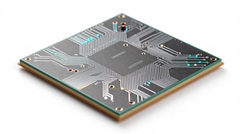
Silicon photonics (SiPh) acts as the primary catalyst for the widespread adoption of 400G Leaf-Spine architectures by integrating laser and optical components directly onto silicon substrates. This integration solves the primary bottleneck of high-speed networking: the 'power and heat' wall. By replacing traditional discrete optical components with integrated circuits, SiPh-based transceivers significantly reduce the energy required to transmit data across the fabric, ensuring that high-density Leaf-Spine configurations remain thermally viable within standard rack cooling limits.
Form Factors: OSFP vs. QSFP-DD in 400G Architectures
The transition to 400G involves a strategic choice between two primary form factors: OSFP (Octal Small Form-factor Pluggable) and QSFP-DD (Quad Small Form-factor Pluggable Double Density). While both support 400Gbps, their design philosophies impact the long-term scalability of Leaf-Spine topologies. QSFP-DD focuses on backward compatibility with legacy QSFP ports, whereas OSFP prioritizes thermal management and a migration path to 800G and 1.6T speeds.
| Feature | OSFP | QSFP-DD |
|---|---|---|
| Thermal Capacity | Higher (Integrated Heatsink) | Lower (Reliant on Port Cooling) |
| Backward Compatibility | Requires Adapter | Native Support for QSFP28 |
| Density | 32 Ports per 1U | 36 Ports per 1U |
| Power Consumption | Slightly Higher but Stable | Lower but Heat Sensitive |
| Future Scalability | Optimized for 800G+ | Limited at Higher Speeds |
Signal Integrity and Latency in Optical Fabrics
In a Leaf-Spine topology, every leaf connects to every spine, creating a massive requirement for consistent signal integrity. Optical interconnects utilizing Silicon Photonics provide superior resistance to electromagnetic interference (EMI) compared to traditional copper DACs (Direct Attach Cables). At 400G speeds, copper's reach is limited to roughly 3 meters, making optical interconnects the only viable solution for spine-to-leaf connections that span larger data center halls, ensuring predictable latency and lower bit-error rates (BER) across the entire fabric.
FAQ: Silicon Photonics and 400G Deployment
- How does Silicon Photonics reduce TCO in a Leaf-Spine network?
SiPh reduces Total Cost of Ownership by lowering power consumption per bit and increasing the reliability of optical modules, which reduces the frequency of manual interventions and cooling requirements. - Is QSFP-DD always better than OSFP due to backward compatibility?
Not necessarily. While QSFP-DD simplifies the transition from 100G, OSFP's superior thermal management makes it more robust for high-performance AI or HPC workloads where switches run at peak capacity. - What is the impact of Silicon Photonics on latency?
By integrating components, SiPh reduces the signal path and complexity within the transceiver, contributing to sub-nanosecond improvements in signal processing latency compared to older discrete optics.
Scalability and Future-Proofing: Transitioning from 400G to 800G

The transition from 400G to 800G represents more than a simple speed increase; it is a fundamental shift in data center density and efficiency that relies on the inherent flexibility of the Leaf-Spine architecture. By decoupling the physical cabling plant from the switch silicon, network architects can upgrade individual spines or leaf nodes to higher-radix 800G ASICs without a wholesale redesign of the infrastructure. This modular approach ensures that investments in 400G today serve as the structural backbone for the 800G and 1.6T ecosystems of tomorrow, minimizing downtime and protecting capital expenditure.
The Modular Advantage: Decoupling Bandwidth from Topology
In a Leaf-Spine architecture, the migration to 800G is primarily driven by the evolution of switch silicon and optical transceivers. Because every leaf is connected to every spine, bandwidth can be increased incrementally. For instance, data centers can begin by deploying 800G-capable spines while maintaining 400G leaf nodes, using breakout cables (e.g., 2x400G) to bridge the generation gap. This pay-as-you-grow model allows for the gradual adoption of higher-speed standards as application demands for AI/ML workloads increase.
Technical Comparison: 400G vs. 800G Infrastructure
| Feature | 400G Standard | 800G Standard | Topology Impact |
|---|---|---|---|
| Transceiver Form Factor | QSFP-DD / OSFP | OSFP800 / QSFP-DD800 | Backward compatibility is often maintained in 800G ports. |
| SerDes Lane Speed | 56Gbps / 112Gbps PAM4 | 112Gbps / 224Gbps PAM4 | Requires higher signal integrity and tighter cable tolerances. |
| Power Consumption | 12W - 14W per port | 16W - 22W per port | Demands enhanced thermal management at the rack level. |
| Max Throughput | 12.8Tbps - 25.6Tbps ASIC | 51.2Tbps+ ASIC | Reduces the total number of switches needed for the same fabric capacity. |
Strategic Migration Path to 1.6T
As the industry looks toward 1.6T, the lessons learned from the 400G to 800G transition become even more critical. The adoption of OSFP as a preferred form factor for high-power optics and the potential integration of Co-Packaged Optics (CPO) will likely occur within the existing Leaf-Spine framework. Keeping fiber counts high and utilizing Single Mode Fiber (SMF) ensures that the physical layer can handle the move from 112G SerDes to 224G SerDes without necessitating a complete 'rip and replace' of the cabling plant.
Scalability and Upgrade FAQ
- Can I use existing 400G fiber for 800G?
Yes, standard Single Mode Fiber (SMF) using LC or MPO connectors is generally compatible with 800G transceivers, though some high-density deployments may prefer newer SN or MDC connectors. - Is 800G backward compatible with 400G switches?
While 800G optics won't run at 800G on a 400G switch, many 800G switch ports can be configured to operate at 400G or use breakout cables to connect to 400G leaf nodes. - When should I prioritize 800G over 400G?
Transition to 800G when your rack density exceeds 400G uplink capacities or when the cost-per-bit for 800G optics reaches parity with 400G, typically driven by AI/HPC requirements.
Deployment Best Practices: Migrating Without Downtime
Deployment Best Practices: Migrating Without Downtime
The transition to a 400G Leaf-Spine architecture is rarely a 'rip-and-replace' event; rather, it is a surgical evolution that requires a parallel fabric approach or a phased pod-by-pod migration to ensure zero-downtime. To achieve a hitless upgrade, engineers must leverage the inherent redundancy of the Leaf-Spine model by deploying new 400G spines alongside existing legacy infrastructure and using BGP (Border Gateway Protocol) weighting or cost-communities to gracefully swing traffic between the old and new control planes.
Strategic Migration Methodologies
When moving from 100G legacy three-tier models or older Clos fabrics to a high-density 400G environment, the choice of migration strategy directly impacts both risk profile and labor costs. Most modern enterprises opt for a 'Parallel Fabric' build, where a secondary 400G spine layer is established, allowing for thorough validation of FEC (Forward Error Correction) settings and optical signal integrity before any production data is migrated.
| Migration Strategy | Downtime Risk | Implementation Complexity | Ideal Use Case |
|---|---|---|---|
| Parallel Fabric Build | Near Zero | High | Mission-critical data centers with available floor space. |
| Phased Pod Replacement | Low | Medium | Scaling existing Leaf-Spine footprints incrementally. |
| Hot-Swapping Spines | Moderate | Low | Small-scale upgrades with robust ECMP load balancing. |
| Big Bang Cutover | Critical | Minimal | Non-production or greenfield environments only. |
Technical Requirements for 400G Interoperability
One of the primary hurdles in 400G migration is the mismatch in Forward Error Correction (FEC) modes between legacy 100G NRZ devices and newer 400G PAM4 optics. Ensuring that leaf switches can support 'breakout' configurations (e.g., 4x100G) requires precise configuration of the transceiver RS-FEC settings. Without aligning these parameters across the fabric, link flaps and high bit-error rates (BER) can cause catastrophic performance degradation during the migration window.
- How do I handle 100G and 400G co-existence?
Utilize 400G switches that support backwards compatibility or use 4x100G breakout cables. This allows you to integrate legacy leaf switches into the new 400G spine layer while gradually upgrading end-nodes. - What is the role of EVPN-VXLAN during migration?
EVPN-VXLAN provides a normalized control plane that abstracts the physical speed of the links. This allows for seamless Layer 2 connectivity across both legacy and 400G pods during the transition period. - How should I manage thermal and power during the upgrade?
400G optics (QSFP-DD/OSFP) consume significantly more power (up to 12W-15W per port) than 100G. Ensure your rack cooling capacity and PDU overhead can handle the increased load before the new spine is energized. - Why is pre-migration optical testing critical?
PAM4 signaling used in 400G is more sensitive to signal loss than NRZ. Using an OTDR or specialized testers to verify fiber cleanliness and bend radius is essential to avoid intermittent CRC errors post-migration.
Finally, any migration to a 400G Leaf-Spine topology must be underpinned by a robust automated testing framework. Before the final cutover, use synthetic traffic generators to saturate links and verify that ECMP (Equal-Cost Multi-Pathing) is distributing flows correctly across the new high-bandwidth spines. This proactive verification mitigates the risk of 'elephant flows' causing congestion in a partially upgraded fabric.
The transition to a 400G leaf-spine topology offers undeniable gains in latency, power efficiency, and scalability, providing the foundation for modern enterprise AI and cloud services. While the initial investment is significant, the long-term TCO and performance advantages make it the clear choice for future-ready data centers. Contact our engineering team today for a custom network audit and start your seamless migration to a high-performance 400G fabric.