As AI and Machine Learning workloads reach unprecedented scales, the demand for high-bandwidth, low-latency interconnects has never been more critical. Moving beyond 400G is no longer just about speed; it is about optimizing the very fabric of the modern data center. This guide evaluates how 800G modules outperform legacy alternatives and why they are becoming the cornerstone of next-generation networking architectures.
The Current State of Optical Interconnects: Why 800G is the New Benchmark

The optical networking landscape has reached a critical inflection point where 400G infrastructure, once the gold standard, is increasingly viewed as a bottleneck for modern hyperscale environments. The rise of 800G as the new performance benchmark is not merely an incremental speed update; it represents a fundamental shift toward higher-density silicon photonics and advanced Digital Signal Processing (DSP) necessary to support the massive East-West traffic flows inherent in AI training and Large Language Model (LLM) deployments.
Catalysts for 800G Adoption: AI and Hyperscale Expansion
The primary catalyst for 800G adoption is the explosive growth of artificial intelligence. AI clusters require low-latency, high-throughput fabrics to facilitate rapid synchronization between thousands of GPUs. As 400G links reach their physical and economic limits in terms of port density and power-per-bit, 800G modules provide the necessary headroom to scale compute fabrics without exponentially increasing the physical footprint of the data center.
| Feature | 400G (Legacy) | 800G (Benchmark) |
|---|---|---|
| Typical Lane Rate | 50G or 100G PAM4 | 100G or 200G PAM4 |
| Port Density | Standard High Density | 2x Density per RU |
| Power Efficiency | ~12-14W per module | ~16-18W per module (Higher bits/watt) |
| Latency Profile | Standard FEC | Low-Latency Optimized FEC |
The Economic Imperative: Power and Density
From a Total Cost of Ownership (TCO) perspective, 800G modules offer a superior value proposition compared to stacking multiple 400G links. By utilizing 112G SerDes technology, 800G interfaces reduce the complexity of the underlying switch fabric. Furthermore, 800G modules in OSFP and QSFP-DD800 form factors allow operators to double their aggregate bandwidth in the same rack unit, effectively deferring expensive facility expansions.
- Why is 800G preferred over two 400G links?
800G reduces the number of required cables and transceivers, lowering the failure rate and simplifying management while providing a significant reduction in power consumption per gigabit of data transmitted. - Is 800G backward compatible with existing infrastructure?
Yes, most 800G ports support breakout configurations (e.g., 2x400G or 8x100G), allowing for a phased migration strategy as legacy equipment is gradually replaced. - How does 800G impact data center cooling?
While 800G modules consume more absolute power than 400G modules, their efficiency is higher. Innovations in thermal management for OSFP modules specifically address the heat dissipation challenges of 800G optics.
Latency Analysis: Measuring the Microsecond Advantage

In high-frequency trading and AI training clusters, the latency budget is measured in nanoseconds, making the shift to 800G modules a critical performance milestone. By doubling the per-lane bandwidth to 112G and utilizing more efficient Digital Signal Processing (DSP) algorithms, 800G architectures significantly reduce the time required for data serialization and error correction compared to parallelizing older 100G or 400G standards, effectively shrinking the processing window for every petabyte of data transferred.
The Three Pillars of Signal Delay
Latency in optical interconnects is not a monolithic figure; it is primarily derived from three technical sources: serialization delay, DSP processing time, and Forward Error Correction (FEC). While the physical speed of light in fiber remains constant, the 'computational bottleneck' occurs within the transceiver modules where signals are converted between electrical and optical domains.
| Technology Standard | Modulation Type | Serialization Delay | Typical DSP/FEC Latency | Relative Total Latency |
|---|---|---|---|---|
| 100G SR4 | NRZ | Highest | < 20ns | Low (Simple) |
| 400G DR4 | PAM4 | Medium | 100-150ns | High (Complex) |
| 800G DR8 | PAM4 | Lowest | 80-120ns | Medium-Low (Optimized) |
Architectural Advantages of 800G Over Alternatives
The move to 800G typically involves the transition to 112G SerDes (Serializer/Deserializer). By doubling the symbol rate, the time required to place a frame on the wire is effectively halved compared to 400G systems using 56G SerDes. This reduction in serialization delay is a primary driver for the microsecond advantage in 800G environments, particularly in large-scale leaf-spine architectures where every hop adds cumulative delay. Furthermore, newer 7nm and 5nm DSPs used in 800G modules are more efficient, processing complex PAM4 signals with fewer clock cycles than the first-generation 400G DSP chips.
The Impact of FEC and DSP-Lite Solutions
While Forward Error Correction (FEC) is essential for maintaining signal integrity in 800G links, it introduces a fixed latency penalty. To counter this, the industry is shifting toward 'DSP-Lite' or Linear Drive Pluggable Optics (LPO). LPO removes the DSP from the module entirely, relying on the host ASIC for signal compensation. This can reduce module-level latency from approximately 100 nanoseconds to sub-10 nanoseconds, providing a massive edge for AI back-end networks that prioritize speed over reach.
Frequently Asked Questions
- Does 800G always have lower latency than 400G?
In most deployment scenarios, yes. The higher baud rate of 800G reduces serialization time, and the more advanced silicon nodes in 800G DSPs process data faster than older 400G counterparts. - How much latency does a typical 800G DSP add?
A standard 800G DSP with active FEC typically adds between 80 to 120 nanoseconds, though this can be significantly reduced if using LPO or specific low-latency FEC modes. - Why is latency critical for AI workloads?
AI training involves constant synchronization between GPUs (All-Reduce operations). Any microsecond delay in the optical link causes GPU 'stall time,' directly increasing the total time and cost of model training.
Power Consumption Profiles: Efficiency at Scale
Power Consumption Profiles: Efficiency at Scale
The transition to 800G architectures is fundamentally driven by the need for energy efficiency, as power consumption now represents the single largest operational cost for hyperscale data centers. While an individual 800G transceiver draws more absolute power (TDP) than a 400G or 100G module, its efficiency—measured in Watts per Gigabit (W/G)—is significantly higher. By consolidating high-speed lanes into a single form factor, 800G modules eliminate the redundant overhead of multiple DSPs, lasers, and cooling management systems required by legacy 'stacked' configurations. This efficiency gain is largely attributed to the adoption of 5nm and 7nm CMOS DSP nodes and the integration of silicon photonics, which allow for higher signal integrity at lower voltage thresholds.
Comparative Power Density Analysis
| Module Configuration | Total Bandwidth | Average TDP (Watts) | Power per Gigabit (mW/G) |
|---|---|---|---|
| Single 800G OSFP/QSFP-DD | 800 Gbps | 16W - 18W | 20.0 - 22.5 mW/G |
| Dual 400G QSFP-DD (2x400G) | 800 Gbps | 24W - 28W | 30.0 - 35.0 mW/G |
| Eight 100G QSFP28 (8x100G) | 800 Gbps | 28W - 36W | 35.0 - 45.0 mW/G |
| Active Optical Cable (800G AOC) | 800 Gbps | 14W - 16W | 17.5 - 20.0 mW/G |
As shown in the table, replacing eight 100G modules with a single 800G module can result in a power saving of nearly 50% for the same throughput. This reduction is not merely academic; it translates directly into lower heat dissipation requirements. In a high-density switch environment where 32 or 64 ports are active, the cumulative power savings of 800G modules significantly lower the 'thermal tax' on the data center's cooling infrastructure, allowing for higher rack density without exceeding the facility's thermal envelope.
Critical Power Efficiency Considerations
- Does 800G generate more heat than 400G?
Individually, yes. An 800G module generates 16-18W compared to 12-14W for 400G. However, since one 800G module replaces two 400G modules, the total heat load per unit of bandwidth is reduced by approximately 25-30%. - How does the move to 112G SerDes affect power?
The shift to 112G SerDes allows for 800G throughput using 8 lanes. While driving signals at 112G requires more precision, the reduction in lane count compared to using 16 lanes of 50G SerDes saves substantial power in the DSP and host interface. - Is LPO (Linear Drive Pluggable Optics) more efficient?
Yes, LPO modules remove the power-hungry DSP from the transceiver, potentially reducing power consumption by up to 50% compared to traditional retimed 800G modules, though they require more complex host-side equalization.
Form Factor Evolution: OSFP vs. QSFP-DD800
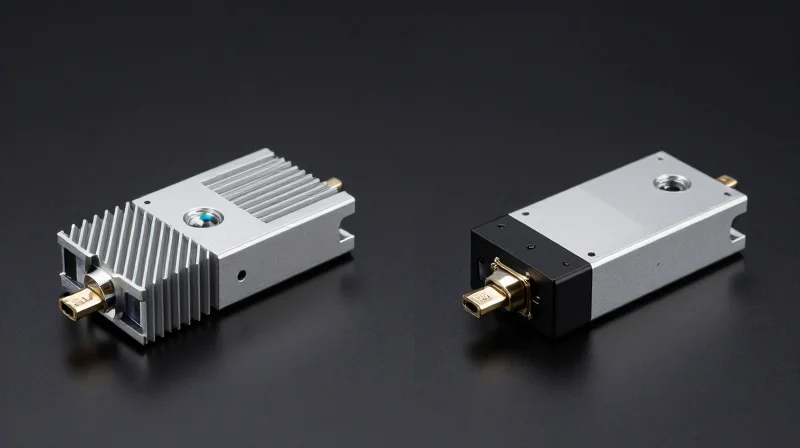
Form Factor Evolution: OSFP vs. QSFP-DD800
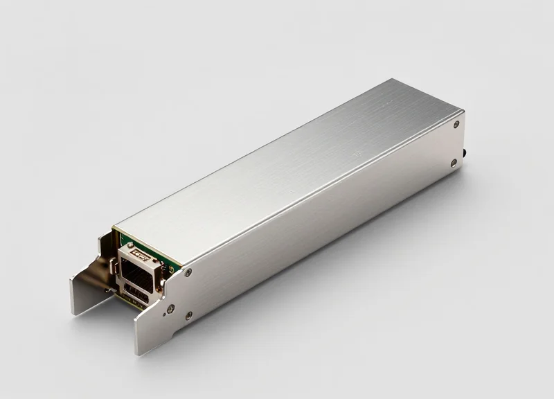
The evolution of 800G hardware is centered on the competition between the Octal Small Form-factor Pluggable (OSFP) and the Quad Small Form-factor Pluggable Double Density 800 (QSFP-DD800). While both support 8x100G electrical lanes, they represent a fundamental trade-off between thermal headroom and backward compatibility. OSFP is designed to handle the extreme power densities of next-generation AI workloads, whereas QSFP-DD800 provides a seamless migration path for operators leveraging existing QSFP infrastructure.
OSFP: The Thermal Architecture of Choice
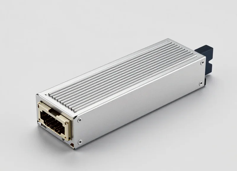
OSFP was engineered with the future in mind, featuring a slightly larger footprint and an integrated heat sink. This design choice is critical for 800G modules, which often operate at higher thermal design power (TDP) than their 400G predecessors. By integrating the cooling fins directly into the module, OSFP can dissipate up to 15-30W per port. This thermal efficiency is vital for maintaining signal integrity and low-latency performance in high-density environments where airflow is often restricted.
QSFP-DD800: Maximizing Density and Legacy Support
QSFP-DD800 maintains the same physical dimensions as previous QSFP generations, ensuring that it remains compatible with a vast ecosystem of legacy ports. While it lacks the integrated cooling fins of the OSFP, it utilizes a stacked connector design to achieve 8-lane density. For data centers where rack space is the primary constraint and the existing cooling infrastructure can support 18-25W modules, QSFP-DD800 offers the most cost-effective path to 800G without requiring a complete hardware overhaul.
| Feature | OSFP | QSFP-DD800 |
|---|---|---|
| Dimensions (W x L) | 22.58mm x 100.4mm | 18.35mm x 89.4mm |
| Max Power Capacity | Up to 30W | Up to 25W |
| Backward Compatibility | Requires Adapter | Direct Support (QSFP28/56) |
| Thermal Management | Integrated Heatsink | System/External Cooling |
| Ideal Use Case | AI/HPC Clusters | Enterprise/Edge Core |
Cooling Impact and Infrastructure Costs
The choice between these form factors directly influences the Total Cost of Ownership (TCO) through cooling requirements. OSFP modules allow for higher air-cooling thresholds, potentially delaying the need for expensive liquid-cooling transitions. Conversely, deploying QSFP-DD800 in high-density configurations may require increased fan speeds and more precise aisle containment, which can elevate operational energy costs. Engineers must weigh the 'plug-and-play' convenience of QSFP-DD800 against the superior thermal stability and lower failure rates associated with the OSFP's cooler operating profile.
- Can OSFP and QSFP-DD800 coexist in the same network?
Yes, they can coexist through the use of breakout cables or switches that support both cage types, though most data centers standardize on one to simplify sparing and maintenance. - Does the form factor affect signal latency?
The physical form factor itself does not change the speed of light, but better thermal management in OSFP can prevent thermal throttling, which ensures consistent latency during peak traffic. - Which standard is winning the 800G market?
Currently, OSFP is seeing higher adoption in greenfield AI and hyperscale deployments due to its 1.6T roadmap, while QSFP-DD800 remains dominant in traditional cloud and enterprise upgrades.
Total Cost of Ownership (TCO): Beyond the Initial Purchase Price

Transitioning to 800G modules represents a strategic shift where the higher upfront purchase price is mitigated by a lower cost-per-bit and significant operational savings. While a single 800G transceiver is more expensive than a 400G equivalent, the consolidation of bandwidth allows for a reduction in total hardware footprint, leading to a leaner, more efficient data center architecture that scales effectively with high-demand AI and cloud workloads.
Capital Expenditure (CAPEX) vs. Operational Efficiency
In a traditional CAPEX model, the acquisition of 800G optics and compatible high-radix switches involves a substantial initial outlay. However, looking at the hardware lifecycle, 800G reduces the quantity of physical units needed to achieve a target aggregate bandwidth. For example, replacing two 400G links with a single 800G link halves the number of ports used on a switch, effectively doubling the capacity of existing rack space and delaying the need for expensive facility expansions.
| Financial/Technical Metric | 800G OSFP/QSFP-DD | 400G (x2) Equivalent | 100G (x8) Legacy |
|---|---|---|---|
| Typical Power per 800G Path | 16W - 24W | 24W - 28W | 32W - 40W |
| Port Density (Per 1U) | High (Up to 25.6T/51.2T) | Medium | Low |
| Cabling Complexity | Low (Optimized Fiber) | Moderate | High (Cable Chaos) |
| Maintenance & Lifecycle | Extended (Future-Proof) | Mid-cycle | Legacy/End-of-Life |
The OPEX Advantage: Power and Cooling Savings
Operating costs in hyperscale environments are dominated by energy consumption. 800G modules, particularly those utilizing latest-generation 5nm DSPs and silicon photonics, offer a superior 'power-per-bit' profile. By moving from 400G to 800G, operators can realize up to a 20% reduction in power consumption for the same data throughput. This energy efficiency trickles down to cooling requirements; fewer watts consumed by the optics means less heat generated, reducing the load on HVAC systems and lowering the PUE (Power Usage Effectiveness) ratio of the facility.
Cabling and Infrastructure ROI
The physical layer of the data center often represents a hidden cost. 800G deployments facilitate the use of higher-density breakout configurations and more efficient fiber management. By utilizing 800G DR8 or 2xFR4 modules, data centers can simplify their structured cabling, reducing the physical volume of fiber in cable trays. This not only lowers the bill of materials for fiber optic assemblies but also improves airflow within the racks, further enhancing thermal management and long-term hardware reliability.
Frequently Asked Questions: 800G TCO
- How does 800G affect the ROI of existing switch hardware?
800G modules allow users to fully utilize the capacity of 51.2T switches. Using lower-speed alternatives often leads to 'stranded' bandwidth or underutilized silicon, which negatively impacts the return on high-cost networking hardware. - Is the cost-per-bit for 800G already lower than 400G?
As production volumes for 800G optics have scaled, the cost-per-bit has reached parity with or dropped below 400G in many high-density scenarios, especially when factoring in the cost of the switch ports. - What is the primary driver for 800G ROI in AI clusters?
In AI clusters, latency and throughput are critical. 800G minimizes the number of 'hops' and physical interconnects required, directly improving job completion times, which is the ultimate metric for ROI in high-performance computing.
The Role of DSP and LPO in 800G Performance

The performance of 800G modules is increasingly defined by the underlying signal processing architecture, where the choice between Digital Signal Processing (DSP) and Linear Drive Optics (LPO) determines whether a network prioritizes signal robustness or ultra-low latency and power efficiency.
DSP-Based Modules: Ensuring Signal Integrity at Scale
Traditional 800G modules rely heavily on DSPs to compensate for signal impairments such as chromatic dispersion and jitter, which are prevalent at high baud rates. By utilizing sophisticated equalization and Forward Error Correction (FEC) algorithms, DSP-based modules ensure a low Bit Error Rate (BER) across longer reaches, typically up to 2km or 10km. However, this robustness comes at the cost of power consumption—often exceeding 16W per module—and added latency due to the processing time required for signal conversion and error correction cycles.
Linear Drive Optics (LPO): The Low-Latency Alternative
LPO technology removes the DSP from the optical module entirely, relying instead on high-performance linear drivers and Transimpedance Amplifiers (TIAs) within the module, paired with the host ASIC's SerDes for equalization. This direct-drive approach eliminates the digital-to-analog conversion steps, slashing latency to sub-nanosecond levels and reducing power consumption by approximately 50%. For AI clusters where every microsecond of tail latency impacts synchronization, LPO presents a compelling architectural advantage for short-reach applications.
| Metric | DSP-Based 800G | LPO (Linear Drive) |
|---|---|---|
| Latency | ~100ns to 250ns | < 1ns (Module level) |
| Power Consumption | 16W - 20W | 8W - 10W |
| Signal Regeneration | Full Digital Recovery | None (Linear Analog) |
| Max Transmission Reach | Up to 10km | Typically < 500m |
| Bit Error Rate (BER) | Superior (Self-correcting) | Dependent on Host SerDes |
Critical Performance Trade-offs in 800G Deployments
While LPO offers significant gains in energy efficiency, it shifts the burden of signal integrity to the network switch. This creates a more complex interoperability environment compared to DSP-based modules, which are effectively 'plug-and-play' due to their internal signal cleaning capabilities. Engineers must weigh the ultra-low latency benefits of LPO against the potential for higher packet loss or reduced reach in larger, more complex fiber fabrics.
- Is LPO compatible with all 800G switches?
No, LPO requires a high-quality host SerDes and specific firmware support on the switch to manage the linear interface, making it less universal than DSP modules. - How does DSP impact tail latency in AI workloads?
The DSP adds serialization and processing delays. In large-scale All-Reduce operations, these nanoseconds accumulate, potentially slowing down the overall training time of large language models. - Can LPO be used for long-distance data center interconnects?
Generally no; LPO is optimized for intra-rack or intra-row connections because it lacks the digital compensation required to overcome fiber degradation over long distances.
Interoperability and Backward Compatibility Challenges
Achieving seamless interoperability for low-latency 800G modules is not a simple 'plug-and-play' endeavor; it requires rigorous synchronization between high-speed SerDes rates, Forward Error Correction (FEC) protocols, and the physical constraints of legacy ports. While 800G offers a massive leap in bandwidth, its reliance on 112G-per-lane electrical signaling often creates friction when interfacing with older 400G or 200G infrastructure that utilizes 56G SerDes, necessitating sophisticated gearboxes or translation layers that can inadvertently introduce latency.
The SerDes Speed Gap: 112G vs. 56G
The primary challenge in backward compatibility lies in the SerDes (Serializer/Deserializer) architecture. 800G modules typically utilize eight lanes of 112G PAM4. When connecting these to legacy 400G switches, which may use eight lanes of 56G, the hardware must perform rate conversion. This mismatch often requires an intermediary 'gearbox' chip within the module or on the line card. While effective for connectivity, these gearboxes add nanoseconds of processing time, which can be detrimental in high-frequency trading or real-time AI training environments where low latency is the primary KPI.
Physical and Electrical Comparison
| Compatibility Feature | OSFP 800G | QSFP-DD800 |
|---|---|---|
| Backward Compatibility | Requires physical adapter for QSFP | Native support for QSFP56/QSFP28 |
| Electrical Interface | 8 x 112G PAM4 | 8 x 112G PAM4 |
| Thermal Management | Superior (Integrated Heatsink) | Standard (Relies on Cage/Heatsink) |
| Legacy Speed Support | 400G (2x200G) / 800G | 200G / 400G / 800G |
The FEC Harmonization Hurdle
Forward Error Correction (FEC) is essential for maintaining bit-error-rate (BER) integrity at 800G speeds, but it is also a significant source of 'architectural latency.' Interoperability issues arise because the IEEE 802.3ck standard for 800G employs more complex FEC schemes than the KP4 FEC used in many 400G deployments. If the host switch and the optical module cannot agree on a common FEC termination point, the link may fail to initialize, or worse, default to a non-optimized state that increases retransmissions and latency.
AECs and Breakout Solutions
To bridge the gap between 800G ports and legacy 100G/400G endpoints, many operators turn to Active Electrical Cables (AECs). These cables contain internal retimers that manage the speed transition and signal conditioning. While AECs solve the physical interoperability problem, they represent a cost-performance trade-off compared to the ultra-low latency of pure Passive Direct Attach Copper (DAC) cables, which are increasingly difficult to implement at 800G over distances exceeding 2 meters.
- Can an 800G QSFP-DD module work in a 400G slot?
Generally no; while the form factor is physically compatible, the power envelope and electrical signaling of an 800G module typically exceed the capabilities of a dedicated 400G port unless specifically designed for multi-rate support. - Does 800G interoperability affect latency?
Yes. Using gearboxes for speed conversion or complex FEC translation to maintain compatibility with older hardware adds incremental latency that may negate some benefits of the 800G upgrade. - What is the 'breakout' challenge?
Breaking out one 800G port into two 400G or eight 100G links requires precise matching of lane speeds and FEC types across the entire cable assembly and both end-points.
AI/ML Workloads: The Primary Driver for 800G Low Latency

AI/ML Workloads: The Primary Driver for 800G Low Latency
800G low-latency modules have transitioned from a luxury to a technical necessity because modern AI/ML workloads are fundamentally bound by the speed of data synchronization across distributed compute clusters. In architectures like Large Language Model (LLM) training, the interconnect is no longer just a transport layer; it is the backbone of the compute fabric itself. High-performance modules reduce the 'tail latency' that often occurs during collective communication operations, ensuring that thousands of GPUs spend more time processing tensors and less time waiting for gradient updates from across the network.
Impact on Distributed Training and GPU Utilization
In distributed training, the All-Reduce and All-to-All communication patterns require massive bandwidth and minimal delay. When using legacy 400G or high-latency alternatives, the network often becomes the primary bottleneck, leading to poor GPU utilization. By doubling the bandwidth to 800G and employing low-latency techniques such as LPO (Linear Drive Optics) or optimized DSPs, data centers can maintain high 'Effective FLOPs' per watt, maximizing the return on investment for multi-billion dollar AI infrastructure.
| Metric | 400G (Legacy Fabric) | 800G (Optimized Fabric) |
|---|---|---|
| Max Throughput | 400 Gbps | 800 Gbps |
| Cluster Sync Speed | Baseline | ~2x Faster Data Exchange |
| Typical GPU Idling | Significant (Congestion-prone) | Minimal (Low-latency pathing) |
| Power Efficiency | Higher Watts/Gbps | Lower Watts/Gbps (LPO/DSP+) |
Real-Time Inference and User Experience
While training demands raw throughput, inference workloads demand responsiveness. For generative AI applications, the 'Time to First Token' and 'Inter-token Latency' are the key performance indicators (KPIs). 800G modules facilitate faster KV (Key-Value) cache loading and more efficient model parallelism. This allows for larger, more complex models to be served with the sub-millisecond responsiveness required for interactive applications like real-time coding assistants and autonomous agents.
- How does 800G reduce training time?
By increasing bandwidth and reducing latency, 800G modules shorten the synchronization window during backpropagation, allowing GPUs to proceed to the next training step faster. - Why is 'tail latency' so critical in AI clusters?
In a synchronized cluster, the entire process moves as slow as the slowest packet. Low-latency 800G modules minimize these outliers, preventing a single slow link from stalling the whole cluster. - Can LPO technology benefit AI workloads specifically?
Yes, Linear Drive Optics (LPO) remove the DSP from the module, significantly reducing both power consumption and latency, which is ideal for the short-reach links typical in AI back-end fabrics.
Navigating the transition to 800G requires a balanced approach to performance benchmarks and financial feasibility. While the jump in speed is significant, the true value lies in the architectural efficiency and latency reductions that define 800G technology. Ready to optimize your network? Contact our technical specialists for a detailed 800G transition roadmap today.