In the rapidly evolving landscape of high-density data centers, the 100G QSFP28 SR4 has long been the workhorse for short-reach connectivity. However, as AI-driven workloads and cloud scaling increase the pressure on network infrastructure, engineers must decide between the cost-effective multimode SR4 and its single-mode rivals like LR4, PSM4, and CWDM4. This guide provides a veteran's perspective on balancing technical performance with long-term financial viability.
The Anatomy of 100G QSFP28 SR4: How Multimode Works
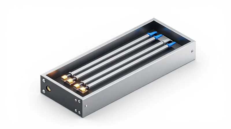
Understanding the 4-Lane Parallel Architecture
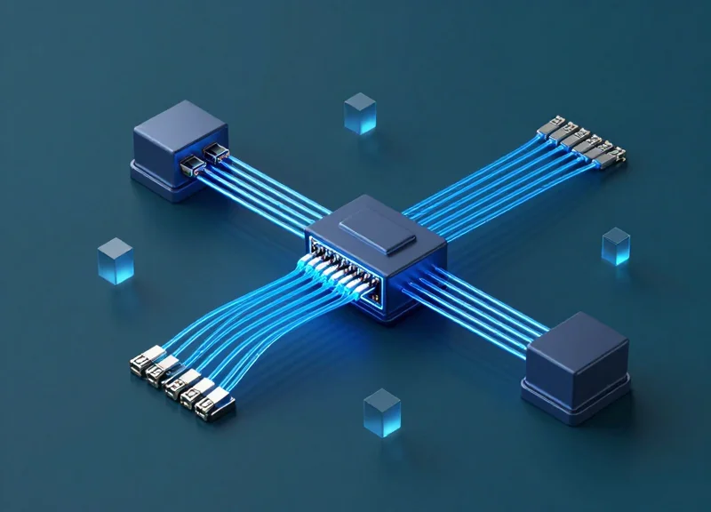
The 100G QSFP28 SR4 (Short Range 4-channel) transceiver achieves its 100 Gbps throughput by utilizing a parallel optical design that aggregates four independent transmit and receive lanes. Each lane operates at a data rate of 25.78 Gbps using Non-Return-to-Zero (NRZ) modulation. Unlike long-reach optics that often employ Wavelength Division Multiplexing (WDM) to send multiple signals over a single fiber pair, the SR4 architecture distributes the load across multiple physical fiber strands. This approach significantly reduces the complexity and cost of the internal optical components, making it the most economical choice for high-bandwidth, short-distance links within data centers.
The Role of MPO/MTP Connectivity
To support its four-lane parallel structure, the QSFP28 SR4 features a Multi-fiber Push-On (MPO) or MTP connector interface. The standard configuration uses an 8-fiber or 12-fiber multimode ribbon. In an 8-fiber setup, four fibers are dedicated to transmitting (TX) and four are dedicated to receiving (RX), while the center fibers in a 12-fiber connector remain unused. This spatial multiplexing over Multimode Fiber (MMF) allows the transceiver to maintain high signal integrity without the need for expensive cooling lasers or complex mux/demux prisms found in single-mode alternatives.
| Parameter | Specification Details |
|---|---|
| Optical Wavelength | 850 nm |
| Modulation Format | NRZ |
| Interface Type | MPO-12 or MPO-8 (Male) |
| Lane Count | 4-Lane Parallel (4x25G) |
| Fiber Type | OM3 / OM4 / OM5 Multimode |
VCSEL Technology and Distance Constraints
The light source for the QSFP28 SR4 is a Vertical-Cavity Surface-Emitting Laser (VCSEL) array. VCSELs are highly efficient and cost-effective for short-range transmission but are limited by modal dispersion inherent in multimode fibers. As the light signal travels through the wider core of an OM3 or OM4 cable, different modes of light travel at slightly different speeds, causing the pulse to spread over time. Consequently, the SR4 is optimized for reach distances of up to 70 meters on OM3 and 100 meters on OM4 or OM5, which is sufficient for most intra-rack and inter-rack connections in modern leaf-spine network topologies.
- Why does SR4 require MPO cabling instead of LC?
Because the SR4 uses a parallel optics architecture, it requires multiple physical fiber strands (4 TX and 4 RX) to transmit the aggregate 100G signal, which the MPO connector provides in a single high-density interface. - Can 100G SR4 be used with Single-Mode Fiber (SMF)?
No, the 850nm VCSEL lasers and the receiver components are specifically designed for the large core diameter of multimode fiber and will not function over single-mode cabling. - What is the benefit of using 4x25G lanes?
It allows for backward compatibility and 'breakout' capabilities, where a single 100G port can be split into four individual 25G connections to serve multiple servers or switches.
SR4 vs. LR4: Bridging the Distance Gap
SR4 vs. LR4: Bridging the Distance Gap
The primary differentiator between 100G QSFP28 SR4 and LR4 lies in the physical transmission medium and the laser technology employed to drive data across it. While SR4 is the standard for short-reach, high-density interconnections within a rack or between adjacent rows, LR4 is engineered to bridge the gap between buildings or across campus environments where distances extend well beyond the 100-meter limit of multimode fiber. Choosing between them is not merely a matter of distance, but a strategic decision involving cable plant costs and power consumption profiles.
The Physics of Light: VCSEL vs. DFB Lasers
At the heart of SR4 modules are four 850nm Vertical-Cavity Surface-Emitting Lasers (VCSELs). These are cost-effective to manufacture and ideal for the parallel fiber architecture of OM3/OM4 cabling; however, VCSELs suffer from high chromatic dispersion, which naturally limits their effective reach. In contrast, the QSFP28 LR4 utilizes four Distributed Feedback (DFB) lasers operating on the LAN-WDM wavelength grid near 1310nm. DFB lasers provide a significantly narrower spectral width and higher output power, allowing signals to travel up to 10km over Single-Mode Fiber (SMF) with minimal signal degradation compared to their multimode counterparts.
| Feature | QSFP28 SR4 | QSFP28 LR4 |
|---|---|---|
| Maximum Reach | 100m (OM4) / 70m (OM3) | 10km |
| Laser Source | 850nm VCSEL | 1310nm DFB (LAN-WDM) |
| Fiber Type | Multimode (MMF) | Single-mode (SMF) |
| Connector Type | MPO-12 (8 fibers used) | LC Duplex (2 fibers used) |
| Typical Power Consumption | < 2.5W | < 3.5W |
Wavelength Management and Connectivity
A critical architectural difference exists in how these modules handle data lanes. The SR4 uses a parallel ribbon of fiber, requiring an MPO-12 connector to manage four independent transmit and receive paths. Conversely, the LR4 employs an internal Optical Multiplexer and Demultiplexer. It combines four 25G channels onto a single fiber pair using Wave Division Multiplexing (WDM). This allows users to leverage existing LC-duplex single-mode infrastructure, which is often more cost-effective for long cable runs despite the higher initial cost of the LR4 transceiver itself.
- Can I connect an SR4 port directly to an LR4 port?
No. They operate on different wavelengths (850nm vs 1310nm) and use different fiber types (Multimode vs Single-mode). They are physically and optically incompatible. - When should I switch from SR4 to LR4?
While SR4 is cheaper for links under 100 meters, you should switch to LR4 once the distance exceeds 100m or if you are connecting between different data center halls where single-mode fiber is the only available medium. - Does LR4 require more power than SR4?
Generally, yes. Due to the complexity of the DFB lasers and the internal WDM mux/demux components, LR4 modules typically consume about 1W more power per module than SR4.
Single-Mode Alternatives: PSM4 and CWDM4 Explained
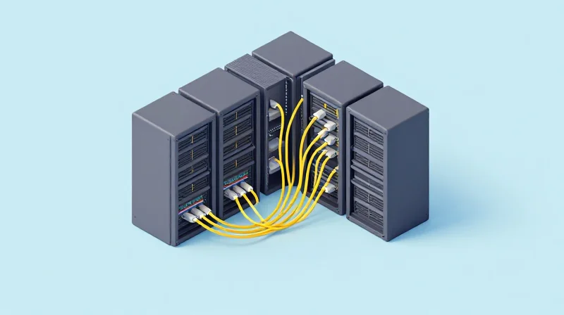
PSM4 and CWDM4 protocols were developed to solve the 'distance-to-cost' dilemma in hyperscale data centers, providing high-speed single-mode connectivity for spans that exceed the 100-meter limit of SR4 but do not require the expensive 10-kilometer reach of LR4. While both utilize single-mode fiber (SMF), they differ fundamentally in how they manage light: PSM4 uses parallel fibers for each lane, whereas CWDM4 multiplexes four wavelengths onto a single fiber pair, allowing for reach capabilities of 500 meters and 2 kilometers, respectively.
PSM4: Cost-Efficient Parallel Single-Mode
The 100G QSFP28 PSM4 (Parallel Single Mode 4-channel) transceiver operates similarly to SR4 but on single-mode fiber. It uses a 1310nm laser and a parallel architecture that requires an 8-fiber or 12-fiber MPO/MTP connector. By using four independent 25Gbps lanes across four separate fibers, PSM4 avoids the need for complex and expensive optical multiplexers/demultiplexers. This makes the transceiver itself more affordable than CWDM4 or LR4, though the total cost of ownership is heavily influenced by the high cost of multi-fiber single-mode cabling over long distances.
CWDM4: Wavelength Multiplexing for Fiber Efficiency
Unlike PSM4, the 100G QSFP28 CWDM4 utilizes Coarse Wavelength Division Multiplexing to combine four different wavelengths (1271, 1291, 1311, and 1331nm) into a single fiber. This allows the module to transmit and receive 100G traffic over a standard LC duplex fiber pair. Because it uses only two fibers regardless of the distance, CWDM4 is significantly more fiber-efficient than PSM4. This efficiency makes it the preferred choice for data centers where fiber infrastructure is limited or where the cost of laying new cables exceeds the premium price of the CWDM4 optics themselves.
Technical Comparison: PSM4 vs. CWDM4
| Feature | 100G PSM4 | 100G CWDM4 |
|---|---|---|
| Max Reach | 500 Meters | 2 Kilometers |
| Fiber Type | Single-Mode (SMF) | Single-Mode (SMF) |
| Cabling Structure | Parallel (8/12-Fiber) | Duplex (2-Fiber) |
| Connector Type | MPO/MTP-12 | LC Duplex |
| Optics Cost | Lower | Higher |
| Cabling Cost | Higher (per meter) | Lower (per meter) |
Frequently Asked Questions
- Can I connect a PSM4 transceiver to a CWDM4 transceiver?
No. PSM4 uses four parallel fibers at the same wavelength, while CWDM4 uses four different wavelengths on a single fiber. They are fundamentally incompatible at the optical layer. - When is PSM4 preferred over CWDM4?
PSM4 is typically preferred in short-reach leaf-spine architectures (under 500m) where the transceiver cost is a major factor and the MPO cabling infrastructure is already in place. - Does CWDM4 require FEC?
Yes, both 100G PSM4 and CWDM4 standards generally require Forward Error Correction (FEC) to be enabled on the host switch ports to ensure link stability and low bit-error rates.
Latency Benchmarking: Why SR4 Leads the Pack

The 100G QSFP28 SR4 leads the pack in latency benchmarking because it employs a 'straight-through' parallel architecture that bypasses the complexities of optical multiplexing. By transmitting data across four discrete spatial lanes (4x25Gbps) using MPO/MTP connectors, SR4 avoids the time-consuming process of combining and splitting wavelengths. In environments like High-Frequency Trading (HFT) and High-Performance Computing (HPC), where nanosecond-level advantages determine success, the SR4’s simplified signal path offers the lowest possible optical processing delay.
Parallel Architecture vs. Wavelength Multiplexing
To understand the latency gap, one must look at how single-mode alternatives like CWDM4 and LR4 operate. These modules use Wavelength Division Multiplexing (WDM) to consolidate four 25G channels onto a single fiber pair. This requires optical prisms, thin-film filters, and more complex TOSA/ROSA (Transmitter/Receiver Optical Sub-Assembly) components. Each stage of filtering and alignment adds infinitesimal but measurable delays. Conversely, SR4 uses a Vertical-Cavity Surface-Emitting Laser (VCSEL) array to fire signals directly into parallel fibers. This absence of 'serial-to-parallel' optical conversion ensures that the signal remains in its native state from the electrical interface to the fiber medium.
| Module Type | Multiplexing Method | Signal Processing | Latency Profile |
|---|---|---|---|
| QSFP28 SR4 | Parallel (4x25G) | Direct VCSEL Drive | Ultra-Low (Baseline) |
| QSFP28 PSM4 | Parallel (4x25G) | Silicon Photonics/DFB | Low |
| QSFP28 CWDM4 | WDM (Optical) | Mux/Demux Filters | Moderate |
| QSFP28 LR4 | WDM (Optical) | Complex Mux/Demux | Higher |
Impact on High-Frequency Trading (HFT)
In the HFT sector, the 'tick-to-trade' latency is the primary metric of performance. While the speed of light in glass is a constant (~5ns per meter), the electronic and optical overhead of the transceiver is a variable that can be optimized. SR4 modules are frequently selected for 'intra-rack' and 'top-of-rack' connections because they minimize jitter. Furthermore, because SR4 operates over shorter distances with high signal integrity, it often encounters fewer Forward Error Correction (FEC) retries, which can otherwise add significant 'tail latency' to a network's performance profile.
Latency and Signal Integrity FAQ
- Does the use of MPO cabling increase latency compared to LC?
No. The connector type (MPO vs. LC) has no impact on signal propagation speed. The latency benefit of SR4 comes from the internal transceiver architecture, not the physical connector housing. - How does Forward Error Correction (FEC) affect SR4 benchmarking?
Standard 100G IEEE 802.3bm requires RS-FEC, which adds roughly 100ns of latency. However, because SR4 has such a simple signal path, it provides a very clean Eye Diagram, allowing some specialized HFT switches to operate in low-latency modes that minimize FEC overhead. - Is the latency difference between SR4 and CWDM4 noticeable?
For standard enterprise data centers, the difference is negligible. However, for clusters running MPI (Message Passing Interface) or high-speed financial transactions, the cumulative nanosecond savings across multiple hops become statistically significant.
Power Consumption Analysis: The Green Data Center Factor

Efficiency by Design: The VCSEL Advantage
The 100G QSFP28 SR4 remains the gold standard for power efficiency in the data center, primarily due to its reliance on Vertical-Cavity Surface-Emitting Laser (VCSEL) technology. While single-mode alternatives like the LR4 or CWDM4 must power more complex Distributed Feedback (DFB) lasers and, in some cases, silicon photonics or temperature-stabilizing components, the SR4 typically draws a maximum of 2.5W. This lower power profile is critical for maintaining a 'Green' data center footprint, directly reducing the total cost of ownership (TCO) beyond the initial hardware purchase.
Comparative Power Consumption Profiles
| Module Type | Typical Power Draw (W) | Max Power Draw (W) | Relative Heat Output |
|---|---|---|---|
| QSFP28 SR4 | 2.0W | 2.5W | Lowest |
| QSFP28 PSM4 | 2.8W | 3.5W | Moderate |
| QSFP28 CWDM4 | 3.0W | 3.5W | Moderate |
| QSFP28 LR4 | 3.5W | 4.5W | Highest |
The Hidden Costs of Thermal Load
Power consumption is not just a utility bill concern; it is a thermal management challenge. Every watt of power consumed by an optical module is converted into heat that must be dissipated by the rack's cooling fans and the facility's CRAC units. In a high-density 32-port 100G switch, choosing SR4 over LR4 can save up to 64 watts of heat load per rack unit. In a hyperscale environment with thousands of links, this difference represents a massive reduction in the energy required for airflow and refrigeration, effectively lowering the facility's Power Usage Effectiveness (PUE) ratio.
Sustainability and Life-Cycle Management
Modern data center operators are increasingly bound by Environmental, Social, and Governance (ESG) mandates. The use of SR4 optics contributes to these sustainability goals by minimizing the carbon footprint associated with both power generation and electronic waste. Because SR4 modules run cooler, they often experience lower component stress, potentially leading to longer mean time between failures (MTBF) compared to single-mode optics that operate at higher internal temperatures.
- Why does a 1-watt difference per module matter?
In a large-scale data center with 10,000 links, a 1-watt saving per port equals 10 kilowatts of constant load. When factoring in cooling overhead, the total power saving can exceed 15-20 kilowatts, leading to tens of thousands of dollars in annual OpEx savings. - Does higher power consumption affect module longevity?
Yes. Electronics operating at higher temperatures generally face accelerated degradation of internal components. SR4 modules, by running cooler, typically enjoy high reliability and consistent performance over their lifecycle. - Are 'Green' optics only for short reach?
While SR4 is the most efficient, newer single-mode standards like 100G DR are closing the gap by using single-lambda technology, though they still struggle to match the sub-2.5W profile of the standard SR4.
Total Cost of Ownership (TCO): Transceivers vs. Fiber Plant
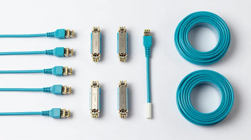
Total Cost of Ownership (TCO): Transceivers vs. Fiber Plant
While the 100G QSFP28 SR4 module often represents the lowest initial capital expenditure for transceivers, its true cost is inextricably linked to the complexity and price of its required cabling. Selecting between SR4 and its single-mode alternatives like CWDM4 or PSM4 is not merely a hardware choice but a strategic infrastructure decision. Because SR4 utilizes parallel optics over multimode fiber (MMF), it requires 8 or 12 strands of fiber per link via MPO/MTP connectors. In contrast, single-mode fiber (SMF) alternatives often utilize duplex LC connectors, leading to a stark difference in cable plant investment as the scale of the data center increases.
The Hidden Costs of Parallel Multimode Fiber
The 'price trap' in 100G deployments often occurs when users overlook the cost per meter of OM3 or OM4 MPO trunk cables. MPO-12 connectors are precision-engineered components that are more expensive to manufacture and more sensitive to contamination than standard LC-Duplex connectors. Furthermore, because SR4 consumes more fiber strands per port, the cost of patch panels, cable management, and 'real estate' within conduits rises proportionally. For a small server room, these costs are negligible; for a hyperscale environment, they can exceed the savings gained from the cheaper SR4 transceivers.
| Cost Factor | QSFP28 SR4 (MMF) | QSFP28 CWDM4 (SMF) | QSFP28 PSM4 (SMF) |
|---|---|---|---|
| Transceiver Cost | Lowest | Moderate | Moderate |
| Fiber Type | OM3/OM4 Multimode | OS2 Single-mode | OS2 Single-mode |
| Connector Type | MPO-12 | LC-Duplex | MPO-12 |
| Cable Cost per Meter | High | Low | Low |
| Reach Capability | Up to 100m (OM4) | Up to 2km | Up to 500m |
Distance as the TCO Decider
The break-even point between SR4 and SMF solutions typically occurs at the 150-meter mark. In short-reach scenarios, such as Top-of-Rack (ToR) switching, the transceiver cost dominates the budget, favoring SR4. However, as distances extend to Middle-of-Row (MoR) or End-of-Row (EoR) configurations, the lower cost of OS2 single-mode fiber begins to offset the transceiver premium. Additionally, OS2 fiber provides a superior upgrade path; while OM4 may struggle with 400G/800G transitions over longer distances, single-mode fiber is virtually future-proof.
- Is SR4 always the cheapest option for 100G?
No. While the SR4 module is cheaper, the required MPO cabling is significantly more expensive than the duplex LC cabling used by CWDM4, often making SMF cheaper for long-distance runs. - How does cable density affect TCO?
SR4 requires 8 to 12 fibers per connection. This consumes physical space in cable trays and patch panels faster than duplex SMF, which only uses two fibers per link. - Which solution offers better long-term ROI?
Single-mode fiber (OS2) generally offers better ROI because the fiber plant does not need to be replaced when upgrading to higher speeds like 400G or 800G, whereas multimode reaches are strictly limited at higher frequencies.
Reliability and MTBF in High-Density Deployments
Reliability and MTBF in High-Density Deployments
In high-density 100G deployments, reliability is primarily governed by the simplicity of the optical engine and the efficiency of heat dissipation. The 100G QSFP28 SR4 standard generally maintains a higher Mean Time Between Failures (MTBF) compared to its single-mode counterparts, such as CWDM4 or LR4, because it utilizes four independent Vertical-Cavity Surface-Emitting Lasers (VCSELs) without the need for complex optical multiplexing or refrigeration components. This architectural simplicity reduces the 'points of failure' within the module, ensuring stable performance in environments where hundreds of transceivers are packed into a single rack.
Component Complexity vs. Failure Rates
The reliability of a transceiver is inversely proportional to the complexity of its internal components. SR4 modules benefit from mature VCSEL technology, which operates at lower currents and generates less waste heat. Conversely, single-mode alternatives like CWDM4 use Distributed Feedback (DFB) lasers and optical mux/demux components that are more sensitive to alignment shifts caused by thermal expansion. When these modules are deployed in high-density leaf-spine architectures, the cumulative heat can accelerate the degradation of the laser diode, leading to premature link failures.
| Transceiver Type | Laser Source | Optical Complexity | Relative MTBF Rating | Typical Power Draw |
|---|---|---|---|---|
| QSFP28 SR4 | 4x VCSEL | Low (Parallel) | Highest | 2.0W - 2.5W |
| QSFP28 PSM4 | 4x DFB | Medium (Parallel) | High | 2.5W - 3.5W |
| QSFP28 CWDM4 | 4x DFB | High (Mux/Demux) | Medium | 3.5W |
| QSFP28 LR4 | 4x EML/DFB | Very High (TOSA/ROSA) | Lower | 3.5W - 4.5W |
Thermal Dissipation and Life Expectancy
Heat is the primary enemy of optical longevity. For every 10°C increase in operating temperature above the recommended threshold, the lifespan of a laser diode can be reduced by nearly half. Because SR4 modules typically draw less than 2.5W, they exert less strain on the data center's cooling infrastructure and maintain lower internal case temperatures. In contrast, 100G LR4 modules, which often require more power for their sophisticated Transmit Optical Sub-Assemblies (TOSA), operate closer to their thermal limits, making them more susceptible to failures in poorly ventilated or high-ambient-temperature environments.
- How does laser count affect MTBF?
Statistically, more components increase the likelihood of a single point of failure. However, the simplicity of the VCSELs in SR4 often outweighs the risks associated with the number of lasers compared to the complex cooling and alignment needs of single-mode lasers. - Why does heat dissipation matter for reliability?
Excessive heat causes wavelength drifting and accelerated semiconductor aging. Lower power modules like SR4 stay within optimal operating parameters longer than high-power alternatives. - Are integrated Silicon Photonics more reliable?
Silicon Photonics (often found in PSM4 or newer CWDM4) can improve MTBF by reducing the number of discrete components, though they still face thermal challenges compared to basic SR4 designs.
Interoperability and Backward Compatibility Standards
Interoperability and Backward Compatibility Standards
Interoperability at 100G is dictated by a balance between optical modulation, fiber media, and physical connector types, where the QSFP28 SR4 standard offers the most seamless transition for existing 40G multimode environments while single-mode alternatives provide the necessary bridge for long-range legacy systems. While SR4 utilizes the same MPO-12 cabling as 40G SR4, ensuring a plug-and-play upgrade for short-reach links, alternatives like CWDM4 and LR4 are designed to maximize the utility of existing duplex LC single-mode fiber plants typically associated with 10G LR and 400G migration paths.
Legacy Infrastructure Alignment and Cable Reuse
The primary challenge in upgrading to 100G is the 'rip and replace' cost of fiber cabling. Choosing a 100G standard that aligns with your current 10G or 40G footprint is critical for minimizing capital expenditure. The following table illustrates how different 100G standards align with legacy media and connectors.
| 100G Standard | Fiber Type | Connector | Legacy Compatibility |
|---|---|---|---|
| QSFP28 SR4 | OM3/OM4 Multimode | MPO-12 | Direct upgrade for 40G SR4 MPO trunks |
| QSFP28 CWDM4 | OS2 Single-mode | Duplex LC | Reuses 10G/40G LR Duplex LC fiber |
| QSFP28 PSM4 | OS2 Single-mode | MPO-12 | Compatible with 40G PLR4/MPO systems |
| QSFP28 LR4 | OS2 Single-mode | Duplex LC | Standard for legacy long-haul 10km links |
Breakout Mode and 4x25G Connectivity
A key feature of QSFP28 interoperability is the support for 'breakout mode.' Since 100G QSFP28 SR4 and PSM4 use four parallel lanes of 25G, they can be split into four individual 25G connections. This allows a single 100G port on a spine switch to connect to four 25G SFP28 ports on leaf switches or servers using a breakout cable (MPO to 4xLC). This backward compatibility is essential for data centers that are incrementally upgrading from 10G/25G to 100G, as it provides high-density port utilization without requiring all endpoints to be 100G-capable simultaneously.
Future-Proofing: The Path to 400G
Selecting a 100G standard also dictates the roadmap to 400G (QSFP-DD). Organizations that deploy 100G PSM4 today find a smoother transition to 400G DR4, as both rely on parallel single-mode fiber architectures. Conversely, those heavily invested in SR4 will likely transition to 400G SR8 or SR4.2. Understanding these trajectories is vital because the transceiver choice made at 100G establishes the physical layer constraints for the next decade of network scaling.
Interoperability FAQ
- Can 100G SR4 communicate with 100G LR4?
No. They operate on different fiber types (Multimode vs. Single-mode) and use different wavelengths (850nm vs. CWDM grid). They are physically and optically incompatible. - Is a QSFP28 port backward compatible with 40G QSFP+?
Generally, yes. Most modern switches allow a QSFP28 port to accept a 40G QSFP+ module, running the port at 40G speeds, though this is hardware-dependent. - Can I use 100G CWDM4 with MPO cabling?
No directly. CWDM4 requires a duplex LC interface. To use MPO trunks, you would need a conversion cassette or a specific patch panel to break the MPO into LC duplex pairs. - Does 100G SR4 support 10G breakout?
While SR4 is designed for 4x25G, many switches allow the lanes to be clocked down to 10G, enabling a 100G port to break out into four 10G links if supported by the NOS.
Strategic Selection: Which 100G Standard Suits Your Architecture?
Strategic Selection: Which 100G Standard Suits Your Architecture?
Choosing the right 100G QSFP28 standard is not merely a question of hardware price but a strategic decision based on your facility's physical fiber topology and future scalability needs. For intra-rack connections under 100 meters where MPO-12 multimode fiber is already prevalent, the SR4 remains the industry standard due to its low power consumption and maturity. However, for spans exceeding 100 meters or environments transitioning to single-mode fiber (SMF) to support 400G and 800G roadmaps, alternatives like PSM4 and CWDM4 become the primary contenders, each offering distinct trade-offs in terms of cabling complexity versus transceiver cost.
100G QSFP28 Decision Matrix
| Standard | Fiber Type | Connector | Max Reach | Primary Application |
|---|---|---|---|---|
| SR4 | Multimode (OM4) | MPO-12 | 100m | ToR to Leaf / Intra-rack |
| SR-BiDi | Multimode (OM4) | LC Duplex | 100m | Retrofitting 10G/40G Duplex MM |
| PSM4 | Single-mode | MPO-12 | 500m | High-density Spine-Leaf / Breakout |
| CWDM4 | Single-mode | LC Duplex | 2km | Enterprise DCI / Campus Links |
| LR4 | Single-mode | LC Duplex | 10km | Long-haul / Metro Core |
Selecting by Deployment Scenario
Architects should follow a tiered approach to selection. In Greenfield Data Centers, deploying single-mode fiber with CWDM4 is increasingly favored; while the transceivers are slightly more expensive than SR4, the duplex LC cabling is significantly cheaper and easier to manage than MPO trunks. In Brownfield Upgrades, if you are replacing 40G SR4 links, the 100G SR4 is a drop-in replacement. If you are upgrading 10G duplex OM3/OM4 and wish to avoid the high cost of new MPO cabling, the SR-BiDi or SWDM4 standards allow for 100G speeds over your existing duplex multimode infrastructure.
- When should I choose PSM4 over CWDM4?
Choose PSM4 when you require 4x25G breakout capabilities to connect a 100G port to four 25G ports, and when the link is under 500 meters. CWDM4 is preferred for point-to-point links between 500m and 2km to minimize fiber counts. - Is the LR4 overkill for a 1km link?
Yes. For a 1km link, CWDM4 is the more cost-effective choice. LR4 is designed for 10km reaches and typically consumes more power and generates more heat, which can impact cooling costs in high-density racks. - How does power consumption vary between these standards?
SR4 typically has the lowest power draw (approx. 2.5W), while LR4 can exceed 3.5W to 4W. In large-scale deployments, choosing SR4 or CWDM4 can result in significant annual electricity savings compared to higher-power long-haul modules.
Choosing the right 100G transceiver is a strategic decision that impacts power, cooling, and future scalability. While the QSFP28 SR4 remains the king of the top-of-rack switch, specific enterprise needs may dictate a move to CWDM4 or LR4. Ready to optimize your network's physical layer? Contact our technical experts today for a comprehensive site audit and component recommendation.