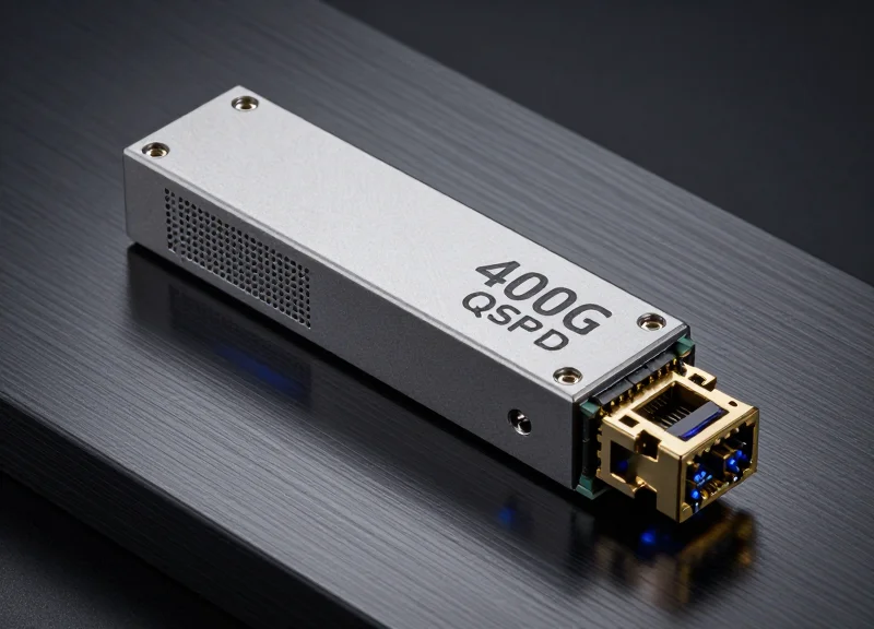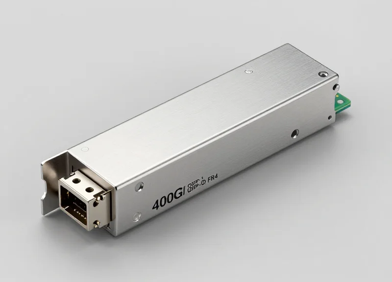
The surge in AI and cloud computing is pushing data centers toward 400G infrastructure. Among the various standards, the 400G FR4 module stands out as a versatile solution for 2km links. This deep dive breaks down the engineering behind the module and why it is the preferred choice for high-density interconnects.
Understanding the 400G Optical Landscape

Understanding the 400G Optical Landscape
The shift to 400G Ethernet marks a pivotal moment in optical networking, necessitated by the relentless demand for bandwidth in hyperscale data centers, cloud computing, and AI-driven workloads. Unlike previous generations that relied on incremental speed increases, 400G represents a fundamental architectural change, moving from Non-Return to Zero (NRZ) signaling to 4-level Pulse Amplitude Modulation (PAM4). This transition allows for doubling the data throughput within the same spectral bandwidth, effectively enabling the density required for modern networking hardware while optimizing the power-per-bit ratio.
The Technological Leap: From NRZ to PAM4
In the 100G era, NRZ was the standard modulation, transmitting one bit per clock cycle using two signal levels. However, as speeds pushed toward 400G, the physical limitations of electrical traces and fiber made NRZ inefficient due to excessive signal loss. 400G ecosystems utilize PAM4, which employs four signal levels to transmit two bits per symbol. This innovation is the foundation of the 400G landscape, allowing manufacturers to achieve 50G or 100G per lane rates, which are then aggregated to reach the 400G threshold.
| Attribute | 100G Ethernet (Legacy) | 400G Ethernet (Modern) |
|---|---|---|
| Modulation Scheme | NRZ (Non-Return to Zero) | PAM4 (Pulse Amplitude Modulation) |
| Signal Levels | 2 Levels (0, 1) | 4 Levels (00, 01, 10, 11) |
| Lane Speeds | 25Gbps per lane | 50Gbps or 100Gbps per lane |
| Standard Form Factor | QSFP28 | QSFP-DD / OSFP |
Standardization and Interoperability
Interoperability is the bedrock of the 400G market, driven by two main entities: the IEEE and Multi-Source Agreements (MSAs). The IEEE 802.3bs and 802.3cu working groups define the primary physical layer specifications, focusing on reach and power consumption. However, because the IEEE process can be slow to adapt to niche market needs, MSAs like the 100G Lambda MSA have stepped in to define industry-standard specifications for optical interfaces like FR4. These agreements ensure that modules from different vendors can work seamlessly together in the same switch environment, preventing vendor lock-in.
- What is the role of the 100G Lambda MSA?
The 100G Lambda MSA is a multi-vendor industry consortium that developed the technical specifications for 100G and 400G optical interfaces using 100G-per-wavelength technology, which is the basis for the FR4 standard. - Why is the industry moving away from QSFP28?
While QSFP28 was ideal for 100G, it lacks the thermal management and electrical pin density required to support 400G throughput, leading to the adoption of QSFP-DD (Double Density). - How does 400G improve data center efficiency?
By increasing port density and reducing the number of physical cables and transceivers needed to move the same amount of data, 400G significantly lowers total cost of ownership (TCO) and power consumption.
Technical Architecture of 400G FR4
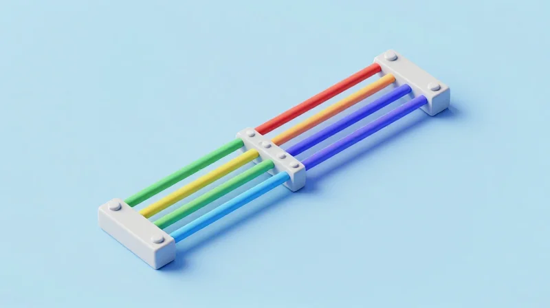
The 4-Wavelength CWDM Architecture
The technical core of the 400G FR4 module lies in its Coarse Wavelength Division Multiplexing (CWDM) design, which allows for the simultaneous transmission of four distinct optical signals over a single pair of single-mode fibers (SMF). Unlike the parallel fiber approach used in SR8 or DR4 modules, FR4 optimizes fiber utilization by multiplexing four 100Gbps channels onto a standard LC duplex connector. This architecture is specifically engineered to bridge the gap between short-reach (DR4) and long-haul (LR4) solutions, providing a cost-effective 2km reach suitable for hyperscale data center leaf-spine fabrics.
The CWDM4 Wavelength Grid
The FR4 specification utilizes the established CWDM4 grid, maintaining 20nm spacing between channels. This wide spacing is intentional, as it allows for the use of uncooled lasers, significantly reducing power consumption and manufacturing complexity compared to LAN-WDM based modules. The following table outlines the specific optical parameters for the 400G FR4 interface:
| Channel | Center Wavelength | Wavelength Range | Optical Lane Rate |
|---|---|---|---|
| L0 | 1271 nm | 1264.5 to 1277.5 nm | 106.25 Gbps (PAM4) |
| L1 | 1291 nm | 1284.5 to 1297.5 nm | 106.25 Gbps (PAM4) |
| L2 | 1311 nm | 1304.5 to 1317.5 nm | 106.25 Gbps (PAM4) |
| L3 | 1331 nm | 1324.5 to 1337.5 nm | 106.25 Gbps (PAM4) |
Signal Processing and PAM4 Modulation
To achieve 400G throughput using only four optical wavelengths, the architecture employs 4-level Pulse Amplitude Modulation (PAM4). On the electrical side, the module typically interfaces with the host via an 8x50G (400GAUI-8) SerDes. A critical component within the module, the Digital Signal Processor (DSP), performs an '8-to-4' gearbox function. This converts the eight electrical lanes into four 100G PAM4 signals that drive the optical transmitters. This transition to 100G-per-lambda is the defining characteristic of second-generation 400G optics, offering higher density and lower cost-per-bit than first-generation solutions.
Key Architectural Components
- Optical Mux/Demux
Passive thin-film filter (TFF) or Arrayed Waveguide Grating (AWG) components used to combine and split the four CWDM wavelengths. - TOSA (Transmitter Optical Sub-Assembly)
Contains four EML (Electro-absorption Modulated Lasers) that provide the high bandwidth and extinction ratio required for 100G PAM4 signals. - ROSA (Receiver Optical Sub-Assembly)
Features high-speed PIN photodiodes and a Transimpedance Amplifier (TIA) to convert the incoming optical pulses back into electrical signals. - DSP with KP4 FEC
The module relies on the host's Forward Error Correction (specifically KP4 FEC) to maintain a pre-FEC Bit Error Rate (BER) that ensures reliable 2km transmission.
The Role of PAM4 Modulation

The Critical Role of PAM4 Modulation
To achieve 400G throughput within the constraints of existing optical components, 400G FR4 modules utilize Pulse Amplitude Modulation 4-level (PAM4) rather than the traditional Non-Return-to-Zero (NRZ) signaling. By employing four distinct signal levels instead of two, PAM4 transmits two bits of data per symbol period. This effectively doubles the data rate at the same baud rate, allowing each of the four CWDM wavelengths in an FR4 module to carry 100Gbps of data (at a 53.125 GBaud rate), which is essential for reaching the aggregate 400G capacity.
Technical Comparison: PAM4 vs. NRZ
The transition from NRZ to PAM4 represents a fundamental shift in how electrical and optical signals are processed. While NRZ is simpler to implement due to its high signal-to-noise ratio (SNR), it becomes bandwidth-prohibitive at speeds above 25Gbps or 50Gbps per lane. PAM4 addresses this by packing more data into the same spectral space, though it introduces increased complexity in signal recovery.
| Feature | NRZ (PAM2) | PAM4 |
|---|---|---|
| Bits per Symbol | 1 bit | 2 bits |
| Signal Levels | 2 (0, 1) | 4 (00, 01, 10, 11) |
| Bandwidth Efficiency | 1x | 2x |
| Signal-to-Noise Ratio (SNR) | High | Low (-9.5dB penalty) |
| Typical Application | 100G (4x25G) | 400G (4x100G) |
Overcoming Signal Degradation with DSP and FEC
Because PAM4 uses four voltage levels, the 'eye' openings in the signal diagram are significantly smaller than those in NRZ. This makes the signal much more sensitive to noise, jitter, and multi-path interference. To maintain a reliable link over the 2km reach specified for FR4, the module integrates a sophisticated Digital Signal Processor (DSP) and relies on Forward Error Correction (FEC), specifically KP4 FEC, to identify and correct bit errors that occur during transmission.
- Why is PAM4 necessary for 400G FR4?
It allows the module to achieve 100Gbps per lane using commercially viable 50Gbaud optical components, staying within the power and thermal envelopes of QSFP-DD or OSFP form factors. - What are the three eyes in PAM4?
In a PAM4 eye diagram, there are three vertical openings between the four signal levels (0/1, 1/2, 2/3), whereas NRZ has only one opening between its two levels. - How does PAM4 impact latency?
PAM4 introduces slightly higher latency compared to NRZ because it requires complex DSP processing and FEC decoding to ensure error-free data delivery.
Key Hardware Specs: Form Factors and Power
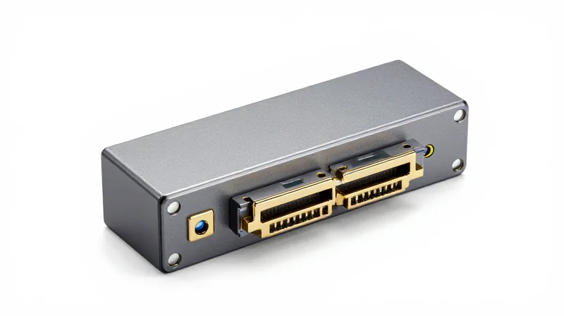
The physical implementation of 400G FR4 technology is defined by two primary form factors—QSFP-DD and OSFP—which facilitate the transition to high-density networking while addressing the significant thermal challenges of 400G optics. As data centers scale, the choice between these form factors depends on existing infrastructure, cooling capacity, and future-proofing needs.
QSFP-DD vs. OSFP: Form Factor Comparison
The Quad Small Form-factor Pluggable Double Density (QSFP-DD) has emerged as a market leader due to its backward compatibility with QSFP28 and QSFP+ modules. By adding a second row of electrical pins, it doubles the bandwidth while maintaining a familiar footprint. In contrast, the Octal Small Form-factor Pluggable (OSFP) is physically larger and was designed from the ground up to support higher power envelopes and better airflow, often featuring an integrated heat sink directly on the module.
| Feature | QSFP-DD (400G FR4) | OSFP (400G FR4) |
|---|---|---|
| Electrical Interface | 8-lane PAM4 | 8-lane PAM4 |
| Backward Compatibility | Yes (with QSFP28/QSFP+) | No (requires adapter) |
| Thermal Capacity | Typically up to 12-14W | Up to 15W+ |
| Module Width | 18.35 mm | 22.58 mm |
| Heat Sink | Flat top (external sink) | Integrated on module |
Power Consumption and Thermal Efficiency
Managing the power envelope is the most critical challenge for 400G FR4 hardware. Most FR4 modules operate within a 10W to 12W power budget. While this is significantly higher than the 3.5W standard of 100G CWDM4, it is highly efficient on a 'per-gigabit' basis. Thermal management is handled through advanced cage designs and, in the case of OSFP, internal cooling fins that allow for higher-wattage components without risking laser degradation or signal instability.
Hardware Specifications FAQ
- Which form factor is better for high-density switches?
QSFP-DD is generally preferred for high-density switches because it allows for 32 to 36 ports in a 1U chassis while maintaining backward compatibility with 100G legacy ports. - Does 400G FR4 require special cooling?
Yes, due to the 10W-12W heat load per module, systems must utilize high-CFM (Cubic Feet per Minute) fans and optimized airflow paths to maintain an operating temperature usually between 0°C and 70°C. - Are QSFP-DD and OSFP modules interchangeable?
No, they are physically and electrically different. You cannot plug a QSFP-DD module into an OSFP slot or vice-versa without specific hardware adapters.
400G FR4 vs. 400G DR4: The Distance Factor
The fundamental distinction between 400G FR4 and 400G DR4 lies in their operational reach and the underlying fiber infrastructure they require; while DR4 is engineered for ultra-short distances up to 500 meters using parallel fiber, FR4 provides a robust solution for links up to 2 kilometers by leveraging duplex single-mode fiber through wavelength multiplexing.
Comparing Transmission Distance and Fiber Efficiency
| Feature | 400G DR4 | 400G FR4 |
|---|---|---|
| Max Reach | 500 Meters | 2 Kilometers |
| Fiber Type | Parallel Single-Mode (PSM4) | Duplex Single-Mode (SMF) |
| Fiber Count | 8 Fibers (4 Tx, 4 Rx) | 2 Fibers (1 Tx, 1 Rx) |
| Connector Type | MPO-12 or MPO-8 | LC Duplex |
| Wavelengths | 4x 1310nm (Parallel) | 1271, 1291, 1311, 1331nm (CWDM) |
The Infrastructure Advantage: Duplex vs. Parallel Fiber
The 400G FR4 module is specifically designed to maximize the utility of existing fiber plants. By using Coarse Wavelength Division Multiplexing (CWDM4), it aggregates four 100G signals onto a single fiber pair. This is a massive cost-saver for enterprises that have already invested heavily in LC-connectorized duplex fiber. In contrast, 400G DR4 requires parallel fiber (MPO), which uses one physical fiber per lane. While DR4 is excellent for top-of-rack (ToR) to leaf switches or for breaking out into 4x100G DR1 connections, the 400G FR4 is the superior choice for spine-to-leaf and inter-building connections where distance exceeds 500 meters.
Operational FAQs: Choosing Between FR4 and DR4
- Can 400G FR4 interoperate with 400G DR4?
No. They use different optical technologies. DR4 uses four parallel fibers at the same wavelength, while FR4 uses four different wavelengths on a single fiber. - When is DR4 preferred over FR4?
DR4 is preferred when the reach is under 500m and there is a requirement to break out the 400G port into four separate 100G DR1 interfaces. - Is 400G FR4 more expensive than DR4?
Generally, FR4 modules are slightly more expensive due to the internal optical multiplexer/demultiplexer components, but they offer lower Total Cost of Ownership (TCO) by reducing fiber cabling requirements.
Link Budget and Optical Performance
Link Budget and Optical Performance
The optical performance of 400G FR4 modules is defined by a stringent link budget designed to support 2km of Single-Mode Fiber (SMF) while overcoming the inherent signal degradation of high-baud-rate PAM4 modulation. To maintain a Bit Error Rate (BER) within the limits of KP4 Forward Error Correction (FEC), these modules must manage a total channel insertion loss of approximately 4.0 dB, accounting for fiber attenuation, connectors, and the internal multiplexing/demultiplexing of the four CWDM wavelengths.
Typical Optical Specifications for 400G FR4
| Parameter | Value (IEEE 802.3cu) | Unit |
|---|---|---|
| Wavelength Grid (CWDM4) | 1271, 1291, 1311, 1331 | nm |
| Maximum Channel Insertion Loss | 4.0 | dB |
| Min. Launch Power (OMAouter) per Lane | -1.5 | dBm |
| Receiver Sensitivity (OMAouter) max | -8.2 | dBm |
| TDECQ (Transmitter and Dispersion Eye Closure) | 3.4 | dB |
| Maximum Dispersion Penalty | 1.6 | dB |
Managing Dispersion and TDECQ
At 53.125 GBaud, 400G FR4 signals are significantly more susceptible to Chromatic Dispersion (CD) and Inter-Symbol Interference (ISI) than previous 100G generations. The primary metric for evaluating this is TDECQ (Transmitter and Dispersion Eye Closure Quaternary), which quantifies the optical power penalty resulting from a non-ideal transmitter and the dispersion effects of the 2km fiber link. Because PAM4 has four distinct signal levels, the 'eye' is much smaller, requiring the receiver to have sophisticated Digital Signal Processing (DSP) to equalize the signal and distinguish between levels amidst the noise floor.
- Why is the 400G FR4 link budget limited to 4.0 dB?
This limit ensures that despite the loss from fiber (0.5 dB/km) and standard connectors, there is enough remaining margin to handle the higher SNR requirements of PAM4 signaling and the signal processing overhead of the DSP. - Is Forward Error Correction (FEC) mandatory for FR4?
Yes, 400G FR4 relies on IEEE 802.3bs/cu KP4 FEC to achieve an error-free post-FEC environment, as the raw pre-FEC BER is typically around 2.4E-4. - How does wavelength affect the link budget?
The CWDM4 grid used in FR4 operates near the zero-dispersion point of G.652 fiber, minimizing chromatic dispersion penalties compared to longer-wavelength solutions like LR4.
Deployment Scenarios in the Data Center

The Strategic Role of 400G FR4 in Data Center Fabrics
400G FR4 modules serve as the critical link for high-density traffic distribution within hyperscale environments, providing an ideal balance between cost-efficiency, reach, and fiber utilization. By leveraging CWDM4 technology to multiplex four wavelengths over a single pair of single-mode fibers (SMF), these modules allow operators to transition from 100G to 400G without the prohibitive expense of deploying new parallel fiber ribbons, which are typically required by DR4 solutions for similar bandwidth requirements.
Optimizing Leaf-Spine Architectures
In a modern leaf-spine topology, 400G FR4 modules are predominantly used for the 'Spine-to-Super-Spine' and 'Leaf-to-Spine' layers. As data center footprints expand, distances between switch tiers often exceed the 500-meter threshold of DR4 optics. The 2km reach of the FR4 specification allows for flexible equipment placement across different rooms, floors, or even separate pods within the same facility. This capability is essential for supporting the massive east-west traffic patterns generated by AI, machine learning, and large-scale cloud computing clusters.
Intra-Campus Data Center Interconnect (DCI)
For campus-scale environments where multiple data center halls are located within close proximity, 400G FR4 serves as a cost-effective alternative to long-haul LR4 or complex coherent optics. It facilitates high-speed synchronization of distributed databases and real-time data replication between adjacent buildings. Because FR4 operates over standard duplex LC fiber, it maximizes the return on investment for existing underground or overhead fiber conduits already in place.
| Deployment Scenario | Primary Module | Max Distance | Fiber Requirement |
|---|---|---|---|
| Top-of-Rack (ToR) to Leaf | 400G DR4 / DAC | 100m - 500m | MPO-12 Parallel SMF / Copper |
| Leaf to Spine (Large DC) | 400G FR4 | 2km | LC Duplex SMF |
| Spine to Super-Spine | 400G FR4 | 2km | LC Duplex SMF |
| Inter-Building Campus DCI | 400G FR4 / LR4 | 2km - 10km | LC Duplex SMF |
Common Deployment Questions
- Can 400G FR4 modules be used to break out into 100G links?
While 400G FR4 uses WDM to multiplex signals onto a single fiber pair, breaking it out into 4x100G is more complex than with DR4. It typically requires a rate-matching switch or a specialized gearbox, as the physical layers (CWDM4 vs. NRZ/PAM4) must be compatible at the endpoint. - Why choose FR4 over LR4 for 2km links?
400G FR4 is generally preferred for 2km reaches because it offers lower power consumption and a lower price point compared to LR4, which is over-engineered for 10km distances and requires more complex laser components. - Is 400G FR4 compatible with legacy 100G CWDM4 fiber plants?
Yes, 400G FR4 is designed to run over the same duplex single-mode fiber infrastructure used by 100G CWDM4, making it a seamless 'drop-in' upgrade for the physical cable plant.
Infrastructure Planning and Thermal Management
When deploying 400G FR4, data center architects must account for the power density of the modules. In high-radix 64-port or 128-port switches, the cumulative thermal output of FR4 optics (often 10W-12W per module) requires robust airflow management. Additionally, because FR4 uses LC duplex connectors, cable management is significantly simplified compared to the bulky MPO cables used for parallel optics, allowing for better airflow and easier maintenance within high-density racks.
Interoperability and Backward Compatibility
Interoperability and backward compatibility are the cornerstones of 400G FR4 module deployment, allowing network architects to integrate these high-speed optics into existing heterogeneous environments without being tethered to a single hardware vendor. By strictly adhering to the IEEE 802.3cu 400GBASE-FR4 standard and the Common Management Interface Specification (CMIS), 400G FR4 modules ensure that the electrical interface on the host switch and the optical signal on the fiber are globally consistent, enabling reliable performance across different equipment manufacturers.
Multi-Source Agreement (MSA) and Standard Compliance
The interoperability of 400G FR4 modules is fundamentally rooted in Multi-Source Agreements (MSAs). These agreements define the mechanical, electrical, and thermal characteristics of the modules. For instance, the QSFP-DD (Quad Small Form-factor Pluggable Double Density) MSA ensures that any compliant module will fit into any compliant switch port, regardless of the brand. This standardization extends to the optical lane specifications, where the 4x100G CWDM grid is precisely defined to prevent signal degradation when mixing transceivers from different vendors at opposite ends of a 2km fiber link.
| Standard / Specification | Focus Area | Interoperability Benefit |
|---|---|---|
| IEEE 802.3cu | Optical Interface | Ensures consistent 400GBASE-FR4 signaling across 2km. |
| QSFP-DD MSA | Mechanical/Electrical | Guarantees physical fit and electrical pin mapping in switch ports. |
| CMIS 4.0/5.0 | Management Interface | Standardizes software communication for diagnostics and monitoring. |
| CWDM4 Grid | Wavelength Logic | Ensures the four 100G lanes match frequency and spacing standards. |
Backward Compatibility and Port Flexibility
Backward compatibility in 400G FR4 is primarily addressed through the design of the host ports and the form factor legacy. The QSFP-DD ports used for 400G FR4 are designed to be physically backward compatible with legacy QSFP28 (100G) and QSFP+ (40G) modules. This allows data center operators to populate a 400G-capable switch with 100G modules during transitional phases, protecting their investment in older fiber infrastructure while preparing for the 400G upgrade.
While 400G FR4 is optimized for point-to-point 400G links using LC duplex fiber, logical interoperability with 100G interfaces is achieved through the switch's silicon. Many modern ASICs allow a 400G port to be 'channelized' into 4x100G. However, unlike the parallel-fiber 400G DR4 which uses MPO breakout cables, FR4 breakout requires an external wavelength demux or a switch-level conversion because its four 100G signals are multiplexed onto a single fiber pair.
Common Interoperability Questions
- Can I use different brands of 400G FR4 modules on the same link?
Yes, provided both modules are compliant with the IEEE 802.3cu 400GBASE-FR4 standard, they are designed to interoperate seamlessly across a duplex single-mode fiber link up to 2km. - Is the 400G FR4 module backward compatible with 100G CWDM4?
Physically, the LC connector is the same, but they are not directly compatible at the optical level because 400G FR4 uses PAM4 modulation while 100G CWDM4 typically uses NRZ modulation. A gearbox or DSP within the switch is required for protocol conversion. - Does 400G FR4 support breakout to 4x100G-FR1?
Direct optical breakout is difficult for FR4 due to its multiplexed nature. Typically, 400G DR4 is preferred for breakout applications, though 400G FR4 can be used in 4x100G mode if the receiving equipment can handle specific CWDM wavelength assignments.
400G FR4 is the backbone of efficient 2km data center links. By leveraging CWDM4 and PAM4, it delivers high performance with reduced fiber complexity. Start upgrading your network today—reach out to our engineers for a custom solution.