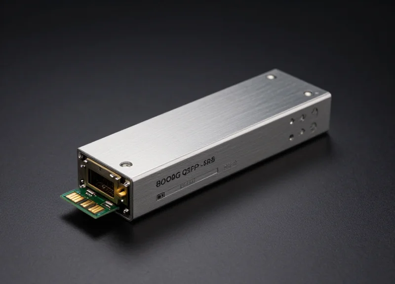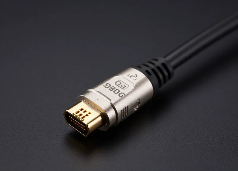
The exponential growth of cloud computing, AI workloads, and streaming media has pushed legacy 100G infrastructures to their breaking point. Moving to 400G is no longer just an upgrade—it is a strategic necessity for modern data centers. In this technical deep dive, we explore the innovations driving this migration and how to overcome the associated deployment challenges.
The Catalysts of the 400G Revolution

The Catalysts of the 400G Revolution
The migration from 100G to 400G represents a fundamental shift in networking infrastructure, driven by a convergence of hyper-scale data center demands and the proliferation of bandwidth-intensive applications. Unlike previous generational leaps, the 400G transition is fueled by the need for higher density, improved power efficiency, and the massive throughput required to support real-time data processing at the edge and in the cloud.
Artificial Intelligence and Machine Learning (AI/ML)
AI and ML workloads are perhaps the most significant drivers for 400G adoption. These applications rely on massive distributed computing clusters where low latency and high-speed interconnects are non-negotiable. As model parameters grow into the trillions, the internal fabric of data centers must scale beyond 100G to prevent networking bottlenecks from stalling GPU utilization and overall training efficiency.
5G Expansion and IoT Ecosystems
The global rollout of 5G networks has introduced a dramatic increase in endpoint density and data volume. With 5G enabling ultra-reliable low-latency communication (URLLC) and massive machine-type communications (mMTC), the underlying backhaul and core networks must transition to 400G to aggregate the influx of traffic from millions of new IoT devices and high-speed mobile connections.
| Driver | 100G Impact | 400G Necessity |
|---|---|---|
| Cloud Video Streaming | Frequent congestion at peak hours | Seamless 4K/8K delivery and concurrency |
| AI Model Training | Network-bound latency issues | High-throughput RDMA and GPU fabric |
| Hyperscale Density | High power/space per Gbit | Optimized power-per-bit and port density |
Efficiency and Economic Scaling
Beyond raw speed, the 400G revolution is motivated by the 'power per bit' metric. 400G transceivers and switches offer significantly lower power consumption and smaller physical footprints compared to the equivalent bandwidth delivered via four separate 100G links. This efficiency is critical for data center operators looking to reduce OpEx while maximizing the utility of existing rack space.
- Why is 100G no longer sufficient for hyperscale centers?
The exponential growth of East-West traffic within data centers has exhausted the capacity of 100G links, leading to complex, power-hungry link aggregation strategies that are less efficient than a single 400G path. - How does 400G benefit edge computing?
400G provides the necessary headroom for edge nodes to process and backhaul massive datasets from local IoT sensors and 5G cells to the central cloud without inducing significant lag.
Architectural Shifts: 100G vs. 400G Overview
The migration from 100G to 400G is not a simple linear upgrade in clock speed; it is a fundamental architectural redesign of the physical and link layers. While 100G infrastructure primarily utilizes Non-Return-to-Zero (NRZ) signaling across four 25Gbps lanes, 400G adopts Pulse Amplitude Modulation 4-level (PAM4) to achieve higher bit density. This shift is necessitated by the physical limitations of high-frequency copper and fiber, where doubling the baud rate of NRZ would result in unsustainable signal degradation and power consumption. Consequently, 400G introduces a complex ecosystem of sophisticated digital signal processors (DSPs) and mandatory Forward Error Correction (FEC) to manage the inherent signal-to-noise ratio challenges of multi-level signaling.
Signaling Evolution: NRZ vs. PAM4
In a 100G NRZ system, data is transmitted using two voltage levels representing '0' and '1'. To scale this to 400G, one would theoretically need 16 lanes of 25G or 8 lanes of 50G, both of which face severe electrical interference and reach limitations. PAM4 addresses this by using four distinct signal levels to represent two bits of information (00, 01, 10, 11) within a single symbol period. This doubles the data throughput without increasing the required bandwidth, though it makes the signal significantly more sensitive to noise.
| Feature | 100G Architecture | 400G Architecture |
|---|---|---|
| Modulation Technique | NRZ (2-level) | PAM4 (4-level) |
| Bits Per Symbol | 1 Bit | 2 Bits |
| Typical Lane Config | 4 x 25Gbps | 8 x 50Gbps or 4 x 100Gbps |
| Error Correction | Optional/Base-R FEC | Mandatory KP4 FEC |
| Typical Form Factor | QSFP28 | QSFP-DD / OSFP |
Form Factors and Physical Density
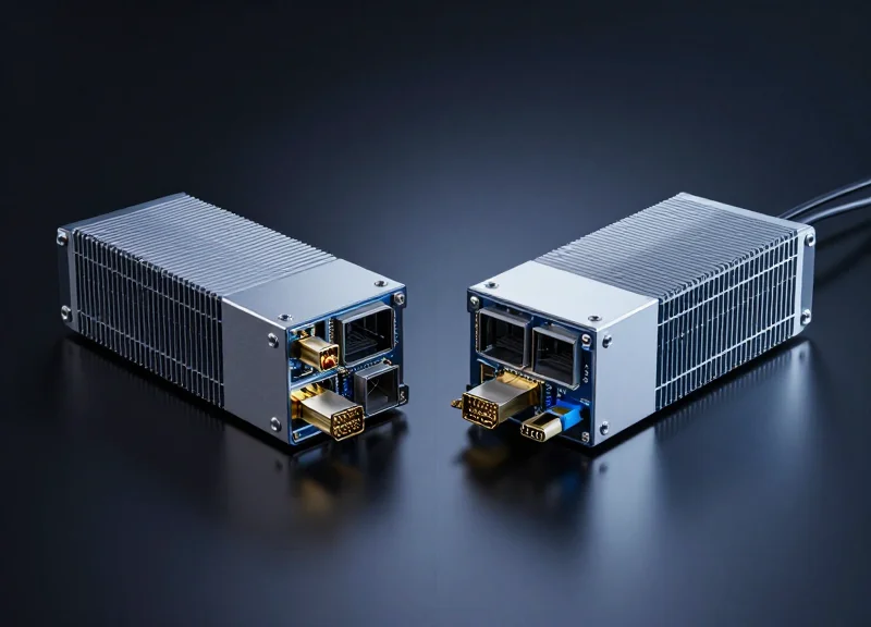
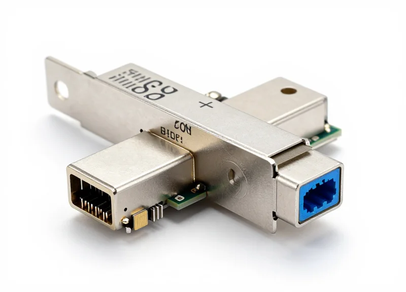
The architectural shift also manifests in physical transceiver design. 100G largely standardized on the QSFP28 form factor. For 400G, the industry has converged on QSFP-DD (Double Density) and OSFP (Octal Small Form-factor Pluggable). QSFP-DD maintains backward compatibility with QSFP28 ports while adding a second row of electrical contacts to support an 8-lane interface. OSFP, while larger, offers superior thermal performance, which is critical for the higher heat dissipation required by 400G DSPs.
Common Architectural Questions
- Why can't we just use faster NRZ for 400G?
As speeds increase, NRZ suffers from extreme insertion loss and inter-symbol interference. Doubling the baud rate to 50GBaud NRZ would reduce the bit period to a point where signal integrity cannot be maintained over standard PCB traces. - Is 400G backward compatible with 100G?
Yes, through the QSFP-DD form factor. A 400G QSFP-DD port can typically accept 100G QSFP28 modules, although it requires the switch silicon to support the varying gearboxing between NRZ and PAM4 signaling. - What is the role of the DSP in 400G?
Unlike many 100G optics that are 'analog,' 400G optics require a Digital Signal Processor (DSP) to manage PAM4 modulation, compensate for fiber dispersion, and perform FEC calculations to ensure a reliable bit error rate (BER).
Understanding PAM4: The Pulse of 400G

PAM4 (Four-Level Pulse Amplitude Modulation) serves as the critical enabler for 400G Ethernet by doubling the data transmission rate per clock cycle without increasing the required frequency bandwidth. Unlike traditional Non-Return-to-Zero (NRZ) modulation, which only uses two signal levels (0 and 1) to convey one bit per symbol, PAM4 utilizes four distinct voltage levels to represent two-bit combinations: 00, 01, 10, and 11. This advancement allows for 50G or 100G per-lane throughput, providing the density required for high-performance data centers while maintaining physical layer compatibility with existing electrical channels.
Technological Efficiency: Baud Rate vs. Bit Rate
The primary motivation for adopting PAM4 is the physical limitation of high-frequency signal propagation. At 400G speeds, an NRZ-based system would require a baud rate so high that signal loss through PCB traces and optical components would become insurmountable. By transmitting two bits per symbol, PAM4 allows the baud rate to remain at 25 or 50 GBaud to achieve 50G or 100G per lane, respectively. This effectively halves the Nyquist frequency relative to the bit rate, reducing insertion loss and extending the reach of both electrical and optical links.
| Feature | NRZ (100G Standard) | PAM4 (400G Standard) |
|---|---|---|
| Voltage Levels | 2 (Low, High) | 4 (0, 1/3, 2/3, 1) |
| Bits per Symbol | 1 Bit | 2 Bits |
| Signal-to-Noise Ratio | High (Large Eye Opening) | Low (Small Eye Opening) |
| Main Implementation | 10G/25G/100G (SR4/LR4) | 400G/800G (DR4/FR4) |
| Error Correction | Optional/Minimal | Mandatory (KP4 FEC) |
Signal Integrity and the Role of FEC
The shift to four-level signaling introduces significant complexity in signal recovery. The signal-to-noise ratio (SNR) is inherently lower in PAM4 because the voltage gaps between levels are much smaller—specifically, the eye height is only one-third that of an NRZ signal. This results in a 9.5 dB SNR penalty. To maintain a reliable Bit Error Rate (BER), 400G systems rely on Forward Error Correction (FEC) and advanced Digital Signal Processing (DSP). These technologies work in tandem to reconstruct degraded signals and correct errors caused by noise, jitter, and inter-symbol interference, which are more prevalent in multi-level modulation schemes.
- Why can't we simply increase the speed of NRZ?
Increasing NRZ speeds beyond 28 Gbps causes exponential signal loss (attenuation) and electromagnetic interference (EMI) that current PCB materials and optical components cannot handle economically. - Does PAM4 increase power consumption?
While PAM4 requires more complex Digital Signal Processors (DSPs), it is more power-efficient on a per-gigabit basis because it moves twice the data over the same physical infrastructure. - What is the difference between Baud Rate and Bit Rate in PAM4?
In PAM4, the bit rate is double the baud rate. For instance, a 50G PAM4 signal has a baud rate of 25 GBaud, because every symbol represents two bits.
Battle of the Form Factors: QSFP-DD vs. OSFP
Battle of the Form Factors: QSFP-DD vs. OSFP
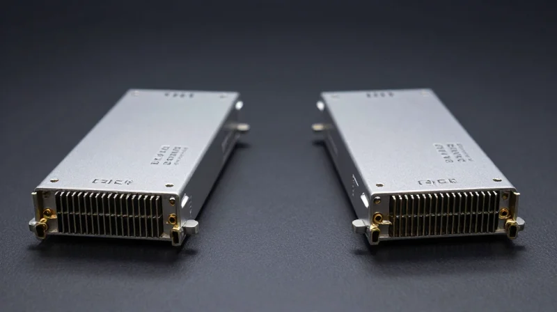
The primary challenge in 400G migration is not just the speed increase, but managing the physical and thermal constraints of the transceiver modules. QSFP-DD and OSFP have emerged as the two dominant standards, with QSFP-DD prioritizing seamless integration with legacy 100G networks through backward compatibility, while OSFP focuses on superior thermal management and a clearer path toward 800G and 1.6T speeds.
QSFP-DD: Prioritizing Density and Legacy Support
QSFP-DD (Quad Small Form-factor Pluggable Double Density) expands on the existing QSFP architecture by adding a second row of electrical contacts. This approach allows a 400G port to be 'backward compatible,' meaning a standard 100G QSFP28 module can be plugged directly into a 400G QSFP-DD port without an adapter. This significantly simplifies the migration path for data centers with massive existing 100G footprints, as it allows for a gradual hardware refresh without replacing every transceiver simultaneously.
OSFP: Engineered for Heat and Future Scaling
The OSFP (Octal Small Form-factor Pluggable) is physically larger than the QSFP-DD and includes an integrated heat sink directly on the module. This design allows it to dissipate significantly more power—up to 15W or more—compared to the initial constraints of the QSFP-DD. While it requires a mechanical adapter to support 100G QSFP28 modules, its superior cooling makes it the preferred choice for high-performance computing (HPC) and AI environments where high-power coherent optics are the norm.
| Feature | QSFP-DD | OSFP |
|---|---|---|
| Max Data Rate | 400G (Scalable to 800G) | 400G (Scalable to 800G/1.6T) |
| Backward Compatibility | Native (QSFP+/QSFP28) | Requires Adapter |
| Power Dissipation | Up to 12-14W | Up to 15-18W+ |
| Size/Dimensions | Smaller (QSFP footprint) | Larger (Integrated heat sink) |
| Port Density (1U) | 36 Ports | 32-36 Ports |
Migration Strategy FAQ
- Which form factor is better for investment protection?
QSFP-DD offers better immediate investment protection for organizations with existing QSFP28 infrastructure due to native backward compatibility. However, OSFP may offer better long-term protection for future 800G/1.6T upgrades due to its thermal headroom. - Does the physical size impact switch density?
Both standards allow for high-density 1U switches (up to 14.4Tbps capacity), but QSFP-DD's smaller size makes it easier to maintain the exact same faceplate density as previous generations. - Is thermal management a deal-breaker?
For standard reach (DR4/FR4), QSFP-DD is sufficient. For long-reach coherent optics (ZR/ZR+), the thermal advantages of OSFP are often necessary to prevent overheating and signal degradation.
Fiber Cabling Infrastructure for 400G Migration
Fiber Cabling Infrastructure for 400G Migration
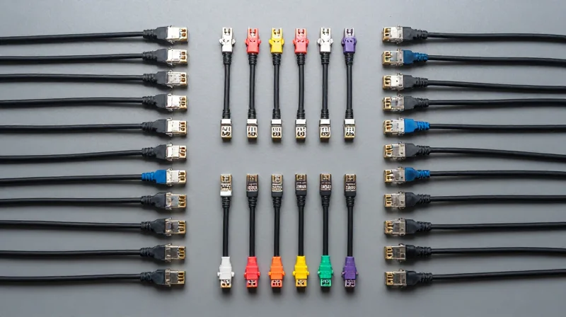
A 400G migration is as much a physical layer challenge as it is a signaling one. Unlike the transition from 10G to 40G, which largely relied on legacy fiber plants, 400G demands a cabling infrastructure capable of supporting higher lane counts and much tighter optical loss budgets. As data centers move from NRZ to PAM4 modulation, the signal-to-noise ratio requirements become more stringent, making connector cleanliness and fiber type selection critical for maintaining signal integrity over distance.
The Shift to MPO-16 and Parallel Optics
Standard 100G deployments often utilize MPO-12 connectors (utilizing 8 or 12 fibers). However, 400G standards like 400G-SR8 utilize 16 fibers—8 for transmit and 8 for receive. This has catalyzed the adoption of the MPO-16 connector, which ensures a 1:1 mapping for 8-lane 400G interfaces. While MPO-12 can still be used via breakout cables or duplex LC in specific configurations like 400G-FR4, the MPO-16 interface is becoming the baseline for high-density, short-reach parallel transmission.
Comparing Fiber Media for 400G
| Fiber Type | 400G Standard | Max Distance | Connector Type |
|---|---|---|---|
| Multi-Mode (OM4/OM5) | 400G-SR8 / SR4.2 | 100m | MPO-16 / MPO-12 |
| Single-Mode (OS2) | 400G-DR4 | 500m | MPO-12 (APC) |
| Single-Mode (OS2) | 400G-FR4 / LR4 | 2km - 10km | Duplex LC |
While Multi-Mode Fiber (MMF) remains a cost-effective choice for short-reach, top-of-rack connections, Single-Mode Fiber (SMF) is seeing unprecedented adoption in 400G architectures. This shift is driven by the fact that PAM4 signals are highly susceptible to chromatic dispersion; SMF provides the necessary bandwidth-distance product to scale beyond 100 meters without the signal degradation often seen in MMF at high speeds.
Infrastructure Migration FAQ
- Can I use existing OM4 fiber for 400G?
Yes, but it is limited to short reaches (typically 100m) using 400G-SR8 or SR4.2 transceivers. Reach is significantly reduced compared to 100G-SR4. - Why is APC polishing critical for 400G Single-Mode?
PAM4 signaling is extremely sensitive to optical return loss. Angled Physical Contact (APC) connectors minimize back-reflection, which is essential for maintaining 400G signal integrity. - Does 400G require more rack space for cabling?
While 400G increases bandwidth, the use of high-density connectors like MPO-16 and CS/SN connectors actually allows for higher port density in the same physical footprint compared to traditional LC-based 100G.
Power Efficiency and Thermal Challenges
The Energy Density Challenge of 400G
While 400G technology offers four times the bandwidth of 100G, it does not do so within the same power footprint. A standard 100G QSFP28 module typically operates within a 3.5W to 5W envelope, whereas 400G modules, such as the QSFP-DD or OSFP, can consume between 12W and 15W, with some high-reach coherent optics exceeding 20W. This tripling of power per slot creates localized hot spots on switch faceplates, requiring a complete rethink of airflow dynamics and heatsink efficiency to maintain operational stability and prevent thermal throttling.
Comparative Power Consumption: 100G vs. 400G
| Module Type | Typical Power Consumption | Total Bandwidth | Efficiency (Watts/Gbps) |
|---|---|---|---|
| QSFP28 (100G SR4) | 3.5W | 100 Gbps | 0.035W |
| QSFP-DD (400G DR4) | 12.0W | 400 Gbps | 0.030W |
| OSFP (400G DR4) | 12.5W | 400 Gbps | 0.031W |
| QSFP-DD (400G ZR) | 18.5W+ | 400 Gbps | 0.046W |
Innovations in Cooling and Thermal Dissipation
To address these increased thermal loads, the industry has pivoted toward several key hardware innovations. The OSFP (Octal Small Form-factor Pluggable) design, for instance, integrates an internal heatsink directly into the module casing to improve heat transfer to the ambient air. For the more compact QSFP-DD, switch manufacturers have developed advanced 'riding' heatsinks and optimized airflow paths that pull heat away from the faceplate more effectively. Furthermore, the transition to 7nm and 5nm semiconductor processes for PAM4 Digital Signal Processors (DSPs) has been crucial in keeping the power-per-bit metric lower than previous generations, even as total power consumption rises.
Operational Challenges FAQ
- How does 400G affect data center PUE?
While 400G transceivers are more efficient per gigabit, the increased cooling demand for high-density 400G switches may slightly increase the Power Usage Effectiveness (PUE) unless the facility adopts containment or liquid cooling strategies. - Why do 400G modules run significantly hotter than 100G?
The primary heat source is the complex PAM4 DSP required for signal processing and Forward Error Correction (FEC). This chip performs billions of calculations per second to maintain signal integrity, generating substantial thermal energy. - Is liquid cooling necessary for 400G migration?
For standard leaf-spine deployments, air cooling remains viable with optimized chassis design. However, for ultra-high-density AI clusters or 800G-ready environments, liquid-to-chip or immersion cooling is increasingly being considered.
Deployment Scenarios: Core, Aggregation, and Edge
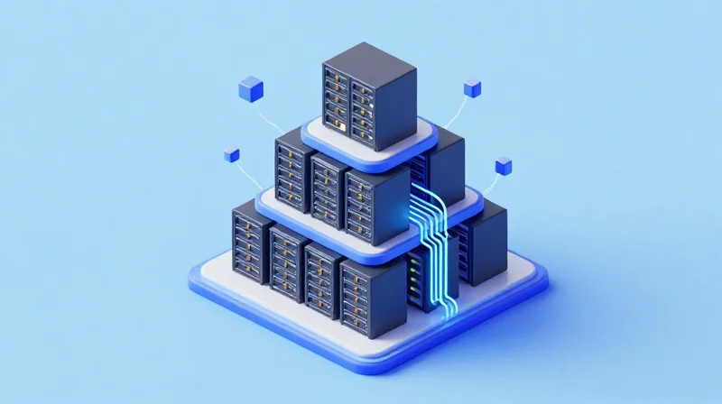
The transition from 100G to 400G is not a uniform hardware replacement but a tiered architectural evolution where performance gains are strategically applied to eliminate specific bottlenecks. By positioning 400G at critical junction points—Core, Aggregation, and Edge—network architects can maximize throughput where traffic density is highest while maintaining cost-effective connectivity for lower-tier segments.
Data Center Core and Data Center Interconnect (DCI)
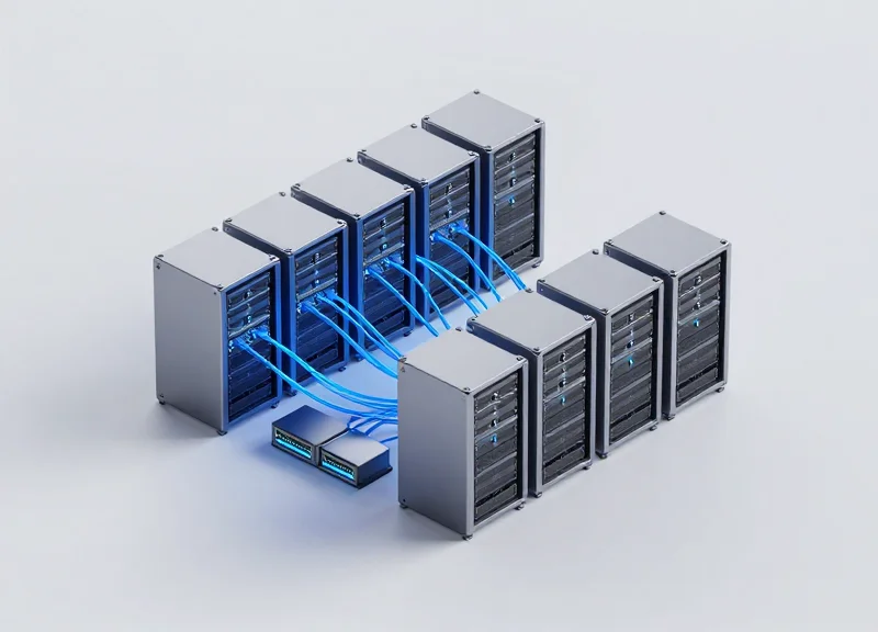
The Core layer is the primary driver for 400G adoption, as it must aggregate massive amounts of East-West traffic from leaf-and-spine architectures. In the Core, 400G allows for a reduction in the total number of physical ports required to achieve Terabit-scale throughput, significantly simplifying cable management. Furthermore, for Data Center Interconnect (DCI), 400G Coherent optics (400G ZR/ZR+) are utilized to bridge the gap between geographically dispersed facilities, offering high-speed transport over hundreds of kilometers without the need for complex external transponders.
The Aggregation Layer: Balancing Density and Cost
At the Aggregation layer, 400G serves as the high-speed 'trunk' that connects multiple 100G Leaf switches to the Spine. The migration strategy here often involves the use of breakout cables (e.g., 400G to 4x100G). This allows operators to upgrade their backbone to 400G while preserving existing investments in 100G Top-of-Rack (ToR) switches. This 'pay-as-you-grow' approach ensures that the migration does not require a total forklift upgrade of the entire network fabric simultaneously.
The Network Edge and AI/ML Clusters
While 400G was once reserved for the Core, the rise of AI/ML workloads and 5G edge computing is pushing these speeds toward the Edge. High-performance computing (HPC) clusters and AI training pods require 400G directly at the server interface to minimize latency and prevent GPU starvation. At the Edge, the focus is on short-reach, high-density modules like 400G SR8 or DR4, providing the rapid data transfer necessary for real-time processing and large-scale model synchronization.
| Network Tier | Primary Function | Typical Distance | Common Transceiver Types |
|---|---|---|---|
| Core / Spine | Backbone Aggregation | 500m - 2km | DR4, FR4, LR4 |
| DCI | Inter-site Connectivity | 80km - 400km+ | ZR, ZR+, CFP2 |
| Aggregation | Leaf-to-Spine Link | 100m - 500m | DR4 (Breakout), SR8 |
| Edge / AI Pods | Server Connectivity | < 100m | SR8, AOC, DAC |
Deployment FAQ
- Can I use 400G in a 100G-only environment?
Yes, through breakout mode. A 400G port can be split into 4x100G channels using specialized breakout cables, allowing for gradual hardware integration. - Is 400G mandatory for the Network Edge?
Not for standard web traffic, but it is becoming essential for AI-driven data centers and low-latency edge nodes where 100G creates significant bottlenecks. - Which tier benefits most from 400G Coherent optics?
The DCI tier benefits most, as Coherent 400G (ZR/ZR+) allows for long-distance transmission over existing fiber without specialized amplification.
The Economics of 400G: Cost per Bit and ROI
The Economics of 400G: Cost per Bit and ROI
The shift from 100G to 400G is fundamentally driven by the economic imperative to handle exponential traffic growth while controlling operational expenditures. While the initial capital expenditure (CapEx) for 400G hardware might appear higher than 100G on a per-unit basis, the total cost of ownership (TCO) tells a different story. 400G technology allows network operators to achieve a much lower cost per bit by consolidating four 100G links into a single 400G interface, which optimizes hardware utilization, reduces the number of required optical fibers, and minimizes the physical footprint within the data center.
Efficiency Metrics: 100G vs. 400G Comparison
| Metric | 4x 100G (QSFP28) | 1x 400G (QSFP-DD) |
|---|---|---|
| Port Density | 4 Ports required | 1 Port required |
| Power Consumption | ~12W - 18W Aggregate | ~12W - 15W Total |
| Cabling Complexity | High (4x discrete links) | Low (1x consolidated link) |
| Relative Cost per Bit | 100% | ~60% to 75% |
Strategic ROI Drivers
Beyond hardware costs, the ROI of 400G migration is accelerated by several key factors. First, the reduction in power consumption per gigabit—often reaching 40% or more—directly lowers utility bills and cooling requirements. Second, the increased density means that existing rack space can support four times the throughput, deferring the need for expensive facility expansions. Finally, 400G optics like 400G-DR4 and 400G-FR4 provide a scalable path toward 800G and beyond, ensuring that current investments remain relevant as bandwidth demands continue to climb.
- Does 400G migration require an entire forklift upgrade?
No. Most modern spine-leaf architectures allow for incremental upgrades where 400G switches are introduced at the core or aggregation layers while maintaining 100G connectivity at the edge using breakout cables. - When is the 'break-even' point for 400G investment?
Most enterprises see a break-even point within 18 to 24 months, driven primarily by OpEx savings in power, cooling, and the reduction in physical port management overhead. - How does 400G affect the cost of optical cabling?
While 400G optics are more advanced, the use of MPO-12 or MPO-16 cabling allows for higher density, which reduces the total volume of fiber required to achieve the same aggregate bandwidth as multiple 100G channels.
Best Practices for a Seamless Migration
Transitioning from 100G to 400G is more than a simple capacity upgrade; it represents a fundamental shift in signaling technology and physical layer requirements. To ensure a seamless migration, network engineers must focus on the nuances of PAM4 (Pulse Amplitude Modulation 4-level) signaling, which is more sensitive to signal-to-noise ratios than the NRZ (Non-Return-to-Zero) used in 100G. A structured approach involving multi-stage testing and strict adherence to interoperability standards is essential for maintaining network uptime and achieving the desired return on investment.
Standardizing Interoperability in Multi-Vendor Environments
In a 400G ecosystem, interoperability is no longer guaranteed by the form factor alone. Engineers must verify the compatibility between QSFP-DD and OSFP modules across different switch vendors. This involves validating not just the physical connection but also the EEPROM/memory map consistency and the firmware support for specific Forward Error Correction (FEC) types. Without standardized FEC—such as KP-FEC or RS-FEC—links may fail to establish or experience high error rates despite having adequate optical power.
Physical Infrastructure and Validation Checklist
| Validation Category | Priority | Key Metric/Action |
|---|---|---|
| Fiber Link Quality | Critical | Verify MPO-12/MPO-16 polarity and end-face cleanliness. |
| Power Budgeting | High | Ensure PDU capacity for modules drawing up to 14W-20W per port. |
| Optical Power Levels | High | Measure Rx power to prevent saturation of sensitive 400G receivers. |
| Transceiver Heat Dissipation | Medium | Confirm airflow patterns match the module's thermal design (C-to-P or P-to-C). |
Mitigating PAM4 Signal Degradation
PAM4 signaling reduces the eye height of the signal compared to NRZ, making it significantly more susceptible to noise and jitter. Best practices include performing 'soak tests' for at least 24 to 48 hours using Bit Error Rate Testers (BERT) to ensure the Pre-FEC BER stays within the 10^-4 to 10^-5 range. This allows the internal silicon to correct errors effectively without causing packet loss or excessive latency. Furthermore, checking the 'Eye Diagram' during initial deployment can identify potential reflection issues in the cabling plant before they impact production traffic.
Migration FAQ: Troubleshooting the 400G Upgrade
- Can I reuse my existing 100G MPO cables?
While the physical fiber may support the distance, 400G often requires MPO-16 or different polarity schemes for breakout configurations; always verify the cable pinout against the specific transceiver data sheet. - Why is my 400G link up but experiencing high latency?
This is often due to 'flapping' or excessive error correction caused by marginal signal integrity. Ensure both ends of the link are using the same FEC standard and check for microscopic debris on connectors. - How do I handle cooling for dense 400G line cards?
Implement a port-staggering strategy if initial thermal loads exceed cooling capacity, and ensure that blanking panels are installed in all empty slots to maintain optimal internal static pressure.
Looking Toward the Horizon: The Road to 800G
The journey toward 800G is a natural extension of the technical innovations established during the 100G to 400G migration. By mastering PAM4 modulation and high-density form factors today, network engineers are laying the groundwork for a future where 800G and 1.6T become the standards for backbone and fabric connectivity. This transition is fundamentally defined by the doubling of the lane rate from 56G to 112G SerDes, allowing for significantly higher throughput without a proportional increase in physical footprint or power complexity.
The SerDes Foundation: From 56G to 112G and 224G
The primary driver for the move to 800G is the shift to 112G SerDes (Serializer/Deserializer) technology. While early 400G deployments were built on 56G PAM4 lanes, the industry's move to 112G allows for 800G interfaces to be realized using just eight lanes. This reduction in lane count per unit of bandwidth is essential for maintaining signal integrity and power efficiency. Looking further ahead, the development of 224G SerDes is already underway to support the 1.6T standard, which will require even more advanced Forward Error Correction (FEC) and potentially new modulation techniques to overcome electrical limitations.
Technological Roadmap: 400G, 800G, and 1.6T
| Feature | 400G Ethernet | 800G Ethernet | 1.6T Ethernet (Future) |
|---|---|---|---|
| Throughput | 400 Gbps | 800 Gbps | 1.6 Tbps |
| SerDes Lane Rate | 56G / 112G | 112G | 224G |
| Standard | IEEE 802.3bs/ck | IEEE 802.3df | IEEE 802.3dj |
| Typical Optics | QSFP-DD / OSFP | QSFP-DD800 / OSFP | OSFP-XD / CPO |
Form Factors and the Rise of Co-Packaged Optics
To support 800G and eventually 1.6T, the industry is optimizing existing form factors like OSFP and QSFP-DD to handle significantly increased thermal loads. However, as speeds reach 1.6T, the power consumed by traditional pluggable optics becomes a major bottleneck due to the electrical loss between the switch ASIC and the optical module. This has accelerated the development of Co-Packaged Optics (CPO). By integrating the optical engines directly onto the same package as the switch silicon, CPO reduces the electrical path length, thereby lowering power consumption and increasing port density beyond what is possible with traditional pluggable modules.
Preparing for 800G: Frequently Asked Questions
- Will current 400G fiber infrastructure support 800G?
In most cases, yes. Single-mode fiber (SMF) plants deployed for 400G (such as DR4 or FR4) are generally compatible with 800G transceivers. However, the transceivers themselves and the switch hardware must be upgraded to support the higher lane rates and throughput. - What role does AI play in the 800G roadmap?
Artificial Intelligence and Machine Learning (AI/ML) workloads are the primary catalysts for 800G adoption. The massive data synchronization required for distributed training clusters necessitates the ultra-low latency and massive bandwidth that only 800G and 1.6T fabrics can provide. - When should organizations begin planning for the 800G transition?
While hyperscale cloud providers are already deploying 800G, large enterprises should begin evaluation now. If your 400G utilization is consistently peaking or if you are planning a greenfield AI data center, the leap to 800G within the next 24 months is a strategic necessity.
Migrating from 100G to 400G is a complex but rewarding journey that requires careful planning and the right hardware choices. By understanding the nuances of PAM4 and form factor evolution, you can future-proof your data center for the next decade of traffic demand. Ready to upgrade your infrastructure? Contact our engineering team today for a comprehensive network assessment.