As data centers transition to 800G to meet the demands of AI and LLM workloads, choosing the right optical architecture is critical. The 800G OSFP 2xFR4 stands at the intersection of high-density performance and cost-efficiency. This guide breaks down how it compares to industry alternatives to help you optimize your infrastructure for the next decade of compute.
The Evolution to 800G: Understanding the OSFP 2xFR4 Standard
The Evolution to 800G: Understanding the OSFP 2xFR4 Standard
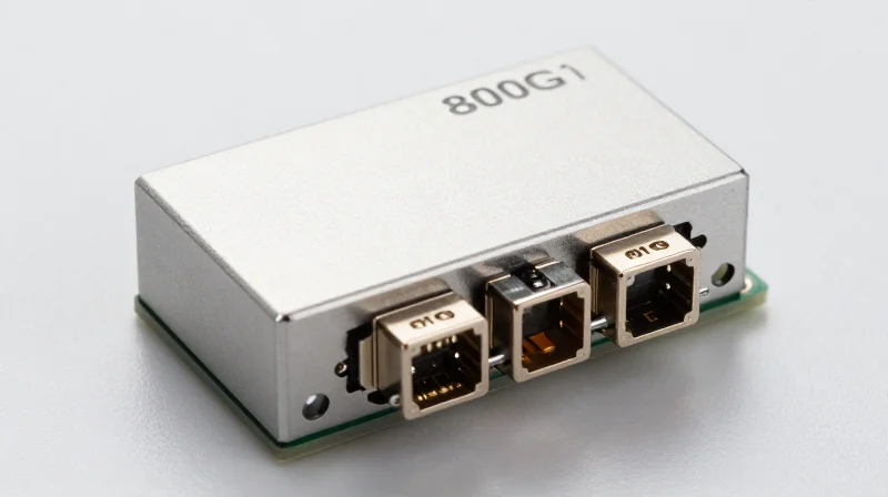
The 800G OSFP 2xFR4 specification is a high-density optical transceiver standard designed to meet the massive bandwidth demands of AI-driven data centers by aggregating two independent 400G FR4 optical engines within a single module. By leveraging Coarse Wavelength Division Multiplexing (CWDM) over two sets of duplex single-mode fibers, it provides a seamless migration path from 400G architectures to 800G. This approach effectively doubles the port density of high-radix switches while maximizing the utility of existing single-mode fiber infrastructure, making it a cornerstone technology for the next generation of hyperscale fabrics.
Core Architecture: Dual 400G Engines
The technical core of the 800G 2xFR4 module lies in its dual-engine design. On the electrical side, the module interfaces with the host via an 8-lane 100G PAM4 (800GAUI-8) signal. Inside the transceiver, this data is split and processed by two independent 400G optical engines. Each engine multiplexes four 100G wavelengths onto a single fiber pair using the CWDM4 grid (1271, 1291, 1311, and 1331 nm). This configuration allows a single 800G port to function either as a monolithic high-speed link or as two breakout 400G FR4 connections, providing unparalleled flexibility in heterogeneous network environments.
| Technical Feature | 800G OSFP 2xFR4 | 800G OSFP DR8 |
|---|---|---|
| Modulation Format | PAM4 | PAM4 |
| Wavelengths | 1271, 1291, 1311, 1331 nm (CWDM) | 1310 nm (Parallel) |
| Fiber Count | 4 fibers (2x Duplex SMF) | 16 fibers (MPO-16) |
| Max Reach | 2km | 500m (Standard) / 2km (Enhanced) |
| Connector Type | Dual CS / Dual LC / MDC | MPO-12 / MPO-16 |
Common Implementation Questions
- Does 800G 2xFR4 support backward compatibility?
Yes, the dual-engine architecture is specifically designed to interoperate with legacy 400G FR4 transceivers through simple breakout cabling, protecting existing hardware investments. - How does CWDM impact total cost of ownership (TCO)?
By multiplexing four wavelengths per fiber, 2xFR4 reduces fiber consumption by 75 percent compared to parallel solutions like DR8, significantly lowering cabling complexity and cost in large-scale deployments. - What are the power requirements?
Standard 800G OSFP 2xFR4 modules typically operate between 14W and 16W, benefiting from the OSFP form factor's superior integrated heat sink for thermal management.
Architecture Deep Dive: 2xFR4 vs. DR8 and 2xLR4
Architecture Deep Dive: 2xFR4 vs. DR8 and 2xLR4
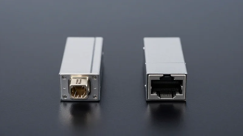
The transition to 800G connectivity is characterized by a fundamental choice between Coarse Wavelength Division Multiplexing (CWDM) and parallel fiber architectures. While the 2xFR4 standard leverages optical multiplexing to minimize fiber count, alternatives like DR8 rely on spatial division, and 2xLR4 utilizes more precise wavelength grids for extended reach. Understanding these internal optical engines is critical for evaluating long-term infrastructure costs and power efficiency.
Internal Optical Engines and Laser Counts
The 800G OSFP 2xFR4 module functions effectively as two independent 400G FR4 engines within a single OSFP form factor. It utilizes 8 lasers in total, grouped into two sets of four. These lasers operate on the CWDM4 grid (1271, 1291, 1311, and 1331 nm). In contrast, the DR8 architecture employs 8 lasers all operating at the same 1310nm wavelength, but instead of multiplexing them onto a single fiber, it outputs them across 8 separate transmit fibers. The 2xLR4 variant mirrors the 2xFR4's dual-engine approach but uses the tighter LAN-WDM grid to maintain signal integrity over the 10km reach.
| Feature | 800G 2xFR4 | 800G DR8 | 800G 2xLR4 |
|---|---|---|---|
| Optical Technique | CWDM4 (Multiplexed) | Parallel Single Mode | LAN-WDM (Multiplexed) |
| Laser Count | 8 (2x4 CWDM) | 8 (Discrete 1310nm) | 8 (2x4 LAN-WDM) |
| Fiber Type | SMF (Duplex) | SMF (Parallel) | SMF (Duplex) |
| Interface Connector | Dual CS / Dual LC | MPO-16 / MPO-12 | Dual CS / Dual LC |
| Max Distance | 2 km | 500 m | 10 km |
Modulation and Path Loss Considerations
All three architectures utilize 100G PAM4 modulation per lane to achieve the aggregate 800G throughput. However, the 2xFR4 and 2xLR4 designs must account for the insertion loss of the internal MUX/DeMUX components, which typically requires higher-performance TOSA (Transmitter Optical Sub-Assembly) units compared to the simpler, direct-path DR8 design. This architectural complexity in 2xFR4 is the trade-off for significantly reduced cabling complexity, as it requires only 4 fibers for a full 800G link compared to the 16 fibers required by DR8.
- Why use 2xFR4 over DR8 for data center interconnects?
2xFR4 is preferred when fiber scarcity is an issue or when upgrading existing 400G duplex fiber plants to 800G, as it avoids the high cost of deploying new MPO-16 cabling required by DR8. - How does 2xLR4 achieve greater distances than 2xFR4?
2xLR4 uses the LAN-WDM wavelength grid, which has narrower spacing and sits closer to the zero-dispersion point of G.652 fiber, allowing for a 10km reach versus the 2km limit of CWDM4-based 2xFR4. - Are the power profiles different between these architectures?
Generally, DR8 modules have a slightly lower power consumption profile because they lack the optical multiplexing components and the thermal stabilization often required for WDM-based modules like 2xFR4 and 2xLR4.
Latency Performance in High-Frequency AI Clusters

Latency Performance in High-Frequency AI Clusters
The adoption of 800G OSFP 2xFR4 in AI back-end networks introduces a deterministic latency penalty primarily driven by the Digital Signal Processor (DSP) required for PAM4 clock and data recovery, which is essential for maintaining signal integrity over CWDM4 wavelengths but can impede the scaling efficiency of latency-sensitive collective communication primitives.
Quantifying the DSP Penalty in 800G Architectures
Unlike legacy NRZ optics, 800G modules operating with 112G-per-lane SerDes rely heavily on DSPs to mitigate inter-symbol interference (ISI) and optical impairments. In an 800G OSFP 2xFR4 module, the DSP must handle two separate 400G engines, performing continuous equalization and retiming. While this ensures a robust link over 2km, the processing time contributes significantly to the total round-trip time (RTT) within the AI cluster. For All-Reduce or All-to-All operations used in training Large Language Models (LLMs), these nanoseconds aggregate across multiple switch hops, potentially leading to GPU under-utilization during synchronization phases.
| Module Category | Processing Engine | Typical Latency | Primary AI Application |
|---|---|---|---|
| 800G 2xFR4 | Full DSP | 100-150ns | Spine-Leaf Interconnect |
| 800G DR8 | Full DSP | 100-150ns | GPU-to-Top-of-Rack |
| 800G LPO | Linear (No DSP) | <5ns | Low-Latency Backend Fabrics |
| 800G AOC | DSP-Lite / Full DSP | 100-120ns | Short-reach clustering |
The Interplay of FEC and Optical Modulation
Beyond the hardware latency of the 2xFR4 module itself, the 800G ecosystem requires mandatory KP4 Forward Error Correction (FEC) to achieve reliable bit-error rates. When comparing 2xFR4 to alternatives like DR8, the FEC overhead remains consistent—adding approximately 100ns to 120ns—but the 2xFR4's use of four distinct wavelengths can introduce minor differential group delay. For the highest frequency AI workloads, minimizing the total 'Time-to-Glass' involves selecting modules where the DSP algorithms are optimized for speed without sacrificing the Bit Error Ratio (BER) required by the network interface cards.
- How does 800G OSFP 2xFR4 affect InfiniBand vs. Ethernet AI clusters?
In InfiniBand environments, where sub-microsecond latency is a primary advantage, the fixed DSP latency of 2xFR4 is more perceptible. In RoCEv2 Ethernet clusters, the network stack latency often dwarfs the DSP delay, making 2xFR4 a balanced choice for reach and cost. - Can LPO replace 2xFR4 for latency-sensitive tasks?
Linear Drive Pluggable Optics (LPO) drastically reduce latency by removing the DSP entirely. However, they lack the signal-shaping power of 2xFR4, meaning they are restricted to shorter distances and require highly precise, high-cost switch ASICs to maintain link stability. - Does 2xFR4 power consumption impact latency?
Indirectly, yes. The high power draw of 800G 2xFR4 DSPs (approx. 14-16W) generates heat that can trigger thermal throttling in dense AI racks, which may introduce jitter and inconsistent latency profiles if not managed by industrial-grade cooling.
Power Consumption: Impact on Data Center Opex
Power Consumption: Impact on Data Center Opex
The 800G OSFP 2xFR4 transceiver architecture is a critical driver for reducing data center OPEX, as it typically operates within a power envelope of 14W to 16W, delivering a highly efficient wattage-per-gigabit ratio that outperforms legacy 400G configurations and competes favorably with parallel-fiber DR8 solutions. By leveraging a dual-engine CWDM design, the 2xFR4 minimizes the electrical-to-optical conversion overhead, directly lowering the energy required for both active signal processing and the massive cooling infrastructure needed to maintain stable operating temperatures in high-density AI clusters.
Comparative Efficiency Metrics
| Module Type | Typical Power Consumption | Fiber Utilization | Max Reach |
|---|---|---|---|
| 800G OSFP 2xFR4 | 14.5W - 16W | Duplex SMF (4 Fibers) | 2km |
| 800G OSFP DR8 | 13W - 15W | MPO-16 (16 Fibers) | 500m |
| 800G OSFP 2xLR4 | 16W - 18.5W | Duplex SMF (4 Fibers) | 10km |
| 2x 400G FR4 (Legacy) | 20W - 24W (Combined) | Dual Duplex SMF | 2km |
While the 800G DR8 module theoretically offers the lowest power consumption due to its simpler parallel optical path, the 2xFR4 provides a superior balance for medium-reach applications. The 'power penalty' for 2xFR4 over DR8 is often less than 1W, a marginal increase that is easily offset by the massive savings in fiber cabling infrastructure and the reduction in optical patch panel complexity. In contrast, 2xLR4 modules require higher bias currents for long-reach lasers, leading to increased thermal dissipation requirements that can strain the cooling capacity of standard air-cooled racks.
The Cooling Multiplier and Infrastructure Costs
In modern hyperscale environments, every watt of power consumed by a transceiver necessitates approximately 0.7 to 1.0 additional watts for cooling and power distribution (PUE factor). For a leaf-spine architecture utilizing thousands of ports, transitioning from 2x 400G legacy modules to a single 800G 2xFR4 module can result in a 30% reduction in total power draw per unit of bandwidth. This reduction simplifies thermal management, allows for higher rack density, and extends the lifespan of the network hardware by reducing the thermal stress on the internal components.
- Does 800G 2xFR4 require special cooling compared to DR8?
No, both utilize the OSFP or QSFP-DD form factors which are designed to handle up to 18-20W. However, the 2xFR4 is slightly more efficient than LR4 variants, making it easier to manage in standard air-cooled environments. - How does the power efficiency of 2xFR4 impact long-term OPEX?
By reducing the total power draw by approximately 3W to 5W compared to two discrete 400G FR4 modules, 800G 2xFR4 significantly lowers electricity bills and carbon footprints over a 3-5 year hardware lifecycle. - Does the use of DSP-based retimers increase power consumption?
Yes, the DSP is the largest power consumer in the module. However, the integration of 112G SerDes in 800G 2xFR4 allows for more efficient processing than older generations, maintaining a low power-per-bit profile.
Cabling Infrastructure: Fiber Count and Complexity
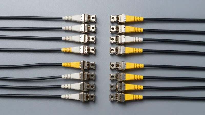
The primary advantage of 800G OSFP 2xFR4 lies in its ability to deliver high-density bandwidth while maintaining the simplicity of traditional duplex fiber infrastructure. By employing Wavelength Division Multiplexing (WDM) to multiplex four 100G lanes onto a single fiber pair (repeated twice for 800G), the 2xFR4 module requires only four fibers total. In contrast, parallel solutions like 800G DR8 or SR8 require 16 fibers per link. This four-fold reduction in fiber count directly translates to lower physical congestion in cable trays and significantly reduces the total cost of ownership regarding passive optical components.
The LC Duplex Advantage vs. MPO Complexity
Managing high-radix switches in hyperscale environments becomes a logistical challenge when using MPO-16 or MPO-12 connectors. Parallel optics require precisely aligned multi-fiber connectors that are more susceptible to dust and signal loss across the array. The 800G OSFP 2xFR4 uses standard LC connectors, which are more robust, easier to clean, and compatible with existing structured cabling plants. This makes the 2xFR4 an ideal 'drop-in' upgrade for data centers already optimized for duplex SMF (Single Mode Fiber).
| Feature | 800G OSFP 2xFR4 | 800G OSFP DR8 | 800G OSFP 2xLR4 |
|---|---|---|---|
| Connector Type | Dual LC (Duplex) | MPO-16 / MPO-12 | Dual LC (Duplex) |
| Fiber Count | 4 Fibers (2 TX / 2 RX) | 16 Fibers (8 TX / 8 RX) | 4 Fibers (2 TX / 2 RX) |
| Cabling Density | Low (Standard LC) | High (Parallel MPO) | Low (Standard LC) |
| Multiplexing | CWDM4 (WDM) | None (Parallel) | LWDM (WDM) |
Impact on Patch Panels and Structured Cabling
When deploying 800G DR8, the sheer volume of fibers necessitates high-density MPO patch panels, which are often more expensive and require specialized polarity management (Method A, B, or C). The 2xFR4 avoids this by leveraging the same duplex LC-to-LC patching used in 100G and 400G FR4 deployments. This allows network engineers to maximize existing rack space without upgrading the physical cable management infrastructure, which can account for up to 20% of the total physical layer cost in new builds.
- Can 800G 2xFR4 be broken out into 400G links?
Yes, because the 2xFR4 uses two sets of 400G FR4 signals, it can easily break out into two 400G FR4 modules using standard LC duplex patch cords without needing complex MPO-to-LC breakout cassettes. - Does the reduced fiber count affect signal integrity?
No, while WDM adds some internal complexity to the transceiver (optical mux/demux), it simplifies the external cabling, leading to fewer points of failure in the patch field. - How does 2xFR4 impact cooling and airflow?
By using four fibers instead of sixteen, cable bulk is reduced by 75% per port. This significantly improves airflow at the front of the switch and within cable managers, aiding in thermal efficiency.
Total Cost of Ownership (TCO) Breakdown
The Total Cost of Ownership (TCO) for 800G OSFP 2xFR4 modules is generally superior for enterprise and cloud data centers that prioritize long-term scalability and fiber conservation. While the unit price of 2xFR4 modules can be higher than parallel-optic alternatives like the DR8 due to the complexity of optical multiplexing, the drastic reduction in fiber count—using only four strands of single-mode fiber via LC duplex connectors versus sixteen strands via MPO—results in a significantly lower overall system cost when accounting for high-density cabling and patch panel infrastructure.
CapEx: Module Costs vs. Infrastructure Savings
In a Capital Expenditure (CapEx) model, the transceiver module is only one part of the equation. For 800G deployments, the cost of the physical layer (cabling, trunking, and distribution) can represent up to 30% of the total network spend. The 2xFR4 standard utilizes Wavelength Division Multiplexing (WDM) to transmit signals over two pairs of fiber. In contrast, the 800G DR8 requires expensive MPO-16 or dual MPO-12 connectors and much thicker cable trunks. By utilizing existing LC infrastructure, operators can often bypass the need for a complete fiber plant overhaul, saving thousands of dollars per rack.
| Feature | 800G OSFP 2xFR4 | 800G OSFP DR8 | 800G OSFP SR8 |
|---|---|---|---|
| Typical Module Price | Higher (WDM complexity) | Medium | Lower |
| Fiber Type | Single Mode (SMF) | Single Mode (SMF) | Multi-Mode (MMF) |
| Cabling Connector | Dual LC Duplex | MPO-16 / MPO-12 | MPO-12 |
| Fiber Density | Low (4 strands) | High (16 strands) | Medium (8-16 strands) |
| CapEx Efficiency | High (Legacy cabling) | Medium (New trunks required) | Low (Limited distance) |
OpEx: Power Consumption and Thermal Efficiency
Operating Expenses (OpEx) are driven primarily by power consumption and the associated cooling costs. The 800G 2xFR4 module typically operates between 14W and 16W. While this is slightly higher than some simple short-reach modules, the efficiency gain is found in the reduced heat generated per gigabit of throughput compared to running legacy 400G units. Furthermore, LC connectors are more robust and less susceptible to contamination than MPO connectors, leading to lower maintenance costs and reduced downtime during routine fiber cleaning or troubleshooting.
Long-Term Value and Lifecycle FAQ
- Why is 2xFR4 considered more future-proof than DR8?
Because 2xFR4 uses standard duplex LC cabling, it allows for a seamless transition from 400G to 800G without replacing the underlying fiber plant. Parallel optics like DR8 often require proprietary or high-density MPO systems that may need replacement as speeds move toward 1.6T. - How does 2xFR4 impact cooling costs?
While the modules generate heat, the reduced physical volume of LC cabling improves airflow within the rack and cable managers, allowing fans to run at lower RPMs and reducing the overall energy footprint of the cooling system. - Is the price premium of the module worth the cabling savings?
Generally, yes. In large-scale deployments, the savings realized by using 75% fewer fiber strands and cheaper LC patch cords more than offsets the higher unit price of the WDM-based 2xFR4 modules.
Final TCO Verdict
When evaluated over a 3-to-5-year lifecycle, the 800G OSFP 2xFR4 provides the most balanced TCO for data centers reaching distances up to 2km. The initial premium paid for the module is a strategic investment that yields dividends through lower infrastructure complexity, reduced maintenance labor, and high compatibility with legacy fiber environments.
Thermal Management: Why OSFP is the Preferred Form Factor
The Thermal Imperative for 800G Networking
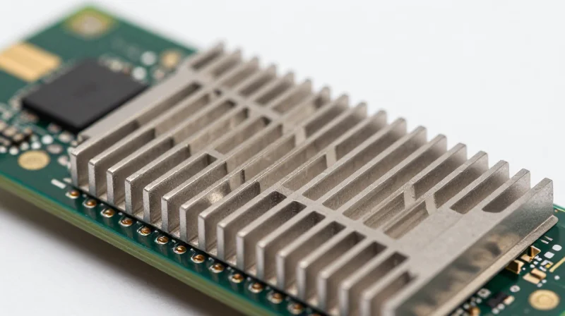
The transition to 800G marks a significant shift in power density, with modules frequently consuming between 16W and 22W depending on the DSP and optical components used. OSFP (Octal Small Form-factor Pluggable) has emerged as the preferred form factor for these high-performance applications because its mechanical design is built specifically to dissipate high heat loads, ensuring that the optics remain within optimal operating temperature ranges even under full line-rate traffic.
Integrated Fins: The OSFP Advantage
Unlike the QSFP-DD, which features a flat-top surface relying on an external heat sink provided by the switch chassis, the OSFP module incorporates integrated thermal fins directly onto the pluggable body. This design maximizes the surface area exposed to the airflow within the switch, facilitating more efficient heat transfer. Because the cooling mechanism is part of the module itself, thermal resistance is minimized, allowing for better airflow consistency across the high-density front panel of a 12.8T or 25.6T switch.
| Feature | OSFP 800G 2xFR4 | QSFP-DD 800G |
|---|---|---|
| Thermal Design | Integrated Heat Sink (Fins) | Flat-Top (Requires External Sink) |
| Power Capacity | Up to 30W+ | Typically limited to 18W-20W |
| Airflow Efficiency | High (Optimized Air Pathways) | Moderate (Dependent on Cage Design) |
| Module Size | Slightly wider/longer | Smaller footprint |
Lowering OpEx through Thermal Efficiency
The thermal efficiency of OSFP translates directly into operational cost savings. In a data center environment, cooling represents a massive portion of the utility bill. Because OSFP modules can operate cooler with less aggressive fan speeds, the overall system power consumption is reduced. Furthermore, maintaining lower junction temperatures for the internal lasers and DSPs extends the Mean Time Between Failures (MTBF), reducing the long-term maintenance costs and hardware replacement cycles associated with 800G deployments.
- Does OSFP require specialized switch cages?
Yes, OSFP requires OSFP-specific cages designed to accommodate its slightly larger size and integrated fins, which provides the necessary thermal path for 800G performance. - Can OSFP modules handle future 1.6T upgrades?
OSFP is specifically designed with a roadmap toward 1.6T, as its thermal envelope can support the 25W-30W+ power draws expected in next-generation optics. - How does the 2xFR4 configuration affect heat?
By using two 400G engines (2xFR4), the thermal load is spread across more components, but the OSFP's superior dissipation ensures these dual engines do not cause localized hotspots.
Deployment Use Cases: From Spine-Leaf to DCI

The Strategic Versatility of 800G OSFP 2xFR4 in Modern Fabrics
The 800G OSFP 2xFR4 serves as a critical bridge in hyperscale architecture, offering a unique middle ground between the high-density parallel fiber requirements of DR8 and the long-haul reach of LR modules. By integrating two 400G FR4 engines into a single OSFP form factor, it provides a seamless migration path for operators who have already invested in LC duplex single-mode fiber (SMF) infrastructure. This allows for a 100% increase in bandwidth capacity without requiring the massive cable plant overhauls associated with MPO-16 or MPO-12 transitions, making it the most cost-effective solution for upgrading existing 400G ecosystems.
Intra-Data Center: High-Radix Spine-Leaf Scaling
In spine-leaf architectures, the 800G OSFP 2xFR4 is primarily utilized for breakout applications and high-density trunking. By utilizing a 2x400G configuration, a single 800G spine port can connect to two independent leaf switches using standard LC-LC patch cords. This 'dual-homing' capability reduces the physical footprint of the spine layer while maintaining the same logical radix as a 400G network. Compared to 800G DR8, the 2xFR4 significantly simplifies cable management by reducing the number of fibers required by a factor of four, which is a major advantage in congested cable trays.
Data Center Interconnect (DCI) and Campus Linkage
Beyond the white space, the 2km reach of the FR4 standard makes the 800G 2xFR4 ideal for Campus DCI. It facilitates high-speed transport between adjacent buildings or halls within a data center campus. While 800G DR8 is limited to 500m, the 2xFR4 provides the necessary optical power budget to traverse longer internal links without the high cost of LR8 (10km) transceivers. This creates a sweet spot for operators who need robust, error-free transmission over intermediate distances at a lower price per gigabit.
| Deployment Scenario | Preferred Module | Key Advantage | Cabling Type |
|---|---|---|---|
| Spine-to-Leaf (Short Range) | 800G DR8 / 2xDR4 | Lowest Latency / Direct Breakout | MPO-12/16 Parallel SMF |
| Spine-to-Leaf (High Density) | 800G 2xFR4 | Fiber Conservation / LC Simplicity | LC Duplex SMF |
| Campus Interconnect (Up to 2km) | 800G 2xFR4 | Extended Reach vs. Cost | LC Duplex SMF |
| Regional DCI (Up to 10km) | 800G LR8 / PLR8 | Long Distance Transmission | LC or MPO-12 SMF |
Deployment FAQ: Choosing the Right 800G Path
- When should I choose 2xFR4 over DR8?
Choose 2xFR4 when your existing cable plant is based on LC duplex SMF or when cable tray congestion prevents the deployment of bulky MPO cables. It is also preferred for any link exceeding 500 meters. - Can 800G 2xFR4 interoperate with 400G transceivers?
Yes, the '2x' architecture is specifically designed for interoperability. One 800G 2xFR4 port can be broken out to connect with two legacy 400G FR4 transceivers, protecting current hardware investments. - Is 2xFR4 suitable for AI/ML clusters?
While DR8 is often favored for the lowest possible latency in AI back-end fabrics, 2xFR4 is increasingly used in the front-end management and storage networks of AI clusters where fiber efficiency and distance are more critical.
Interoperability and Future-Proofing
The 800G OSFP 2xFR4 serves as a critical bridge in data center evolution, offering a unique 'dual-engine' architecture that enables direct interoperability with existing 400G FR4 interfaces. Unlike parallel alternatives that require complex breakout cables or entirely new fiber plants, the 2xFR4 leverages established duplex LC infrastructure, ensuring that current hardware investments remain relevant while providing a clear migration path to 1.6T Ethernet standards. This interoperability is not merely a convenience; it is a strategic necessity for operators managing heterogeneous environments where 400G and 800G hardware must coexist.
Backward Compatibility with 400G FR4 Ecosystems
The primary strength of the 2xFR4 configuration lies in its ability to split its 800G aggregate bandwidth into two independent 400G circuits. By utilizing the CWDM4 wavelength grid, it maintains optical consistency with legacy 400G FR4 transceivers. This allows network operators to upgrade switch ports to 800G density without forcing a synchronous upgrade of the entire link partner ecosystem, effectively doubling port density while maintaining support for existing 400G infrastructure.
| Feature | 800G OSFP 2xFR4 | 800G DR8 / SR8 | Legacy 400G FR4 Support |
|---|---|---|---|
| Fiber Type | Single-mode (Duplex LC) | SMF/MMF (MPO-16/12) | Single-mode (Duplex LC) |
| Breakout Capability | 2x 400G FR4 | 8x 100G DR/SR | N/A (Native) |
| Cabling Complexity | Low (Existing Duplex) | High (Parallel Fiber) | Low |
| Optical Grid | CWDM4 | Parallel 1310nm | CWDM4 |
The Roadmap to 1.6T and OSFP1600
The industry's move toward 1.6T (2x800G) relies heavily on the thermal and electrical performance characteristics pioneered by the OSFP form factor. Because the 800G OSFP 2xFR4 already manages the thermal challenges of 112G SerDes within the OSFP shell, the transition to 1.6T—utilizing 224G SerDes—is a natural evolution. Adopting OSFP today for 800G 2xFR4 deployments ensures that the physical layer infrastructure, including racks and cooling systems, is already optimized for the upcoming OSFP1600 standard.
Future-Proofing FAQ
- Can 800G 2xFR4 connect directly to 400G FR4 ports?
Yes. Through a simple LC-to-LC duplex patch or breakout, the 800G 2xFR4 can interface with two separate 400G FR4 modules, provided the host switch supports port breakout mode. - Why is OSFP considered more future-proof than QSFP-DD for 1.6T?
OSFP offers superior thermal dissipation (up to 30W+ per module) and integrated heat sinks, which are essential for the high-power consumption expected in 1.6T DSPs and 224G SerDes architectures. - Does 2xFR4 support the upcoming 800G-LR4 standards?
While 2xFR4 is optimized for 2km reaches, its architecture shares the CWDM heritage of the LR4 standards, though 800G-LR4 typically moves to a single 800G lambda or 4x200G configuration, making 2xFR4 the preferred choice for legacy 400G breakout specifically.
Strategic Decision Matrix for 800G Upgrades
Strategic Decision Matrix for 800G Upgrades
The optimal 800G upgrade strategy hinges on aligning specific data center topology requirements with the physical and thermal limitations of OSFP form factors, ensuring that immediate bandwidth needs do not compromise the long-term scalability of the optical fabric.
Comparative Performance and Resource Allocation
| Module Type | Max Reach | Fiber Media | Primary Application | Power Profile |
|---|---|---|---|---|
| 800G OSFP 2xFR4 | 2km | Duplex SMF | Spine-Leaf / Campus | Moderate (14-16W) |
| 800G OSFP DR8 | 500m | Parallel SMF (MPO-16) | Top-of-Rack Breakout | Low (12-14W) |
| 800G OSFP SR8 | 100m | Parallel MMF (MPO-16) | Intra-rack Computing | Efficient (10-12W) |
| 800G OSFP 2xLR4 | 10km | Duplex SMF | Metro / DCI | High (16-18W) |
When evaluating Total Cost of Ownership (TCO), architects must look beyond the initial transceiver price. The 2xFR4 module offers a unique value proposition by utilizing existing duplex single-mode fiber (SMF) infrastructure, which significantly reduces the CapEx associated with complex MPO-16 cabling required by DR8 and SR8 alternatives.
Selection Guide: Use Case Alignment
- When should I prioritize 800G 2xFR4?
Choose 2xFR4 for high-density interconnects reaching up to 2km where fiber conservation is critical. It is the preferred choice for scaling spine-leaf architectures without upgrading existing LC-patching infrastructure. - Is DR8 better for breakout scenarios?
Yes. 800G DR8 is purpose-built for breaking out a single 800G port into eight 100G or two 400G links, making it ideal for connecting high-radix switches to legacy servers. - How does thermal management impact the decision?
In high-density deployments, the OSFP form factor's superior integrated heat sink allows 2xFR4 modules to run more reliably at lower temperatures compared to QSFP-DD equivalents, reducing cooling-related OpEx. - What is the impact on future-proofing?
Selecting the OSFP 2xFR4 path aligns with the industry roadmap for 1.6T and 3.2T systems. The infrastructure established for 800G dual-carrier optics provides a seamless transition to next-generation Ethernet speeds.
Ultimately, the decision to deploy 800G OSFP 2xFR4 vs. alternatives rests on a balance of reach and radix. For massive-scale AI and cloud data centers, the density and reach of 2xFR4 provide the most versatile foundation for evolving network demands.
Choosing between 800G standards requires balancing immediate capital expenditure with long-term operational efficiency. The 800G OSFP 2xFR4 offers a compelling path for high-density environments seeking to minimize fiber costs while maintaining peak performance. Contact our engineering team today for a custom network assessment or to request sample units for testing.