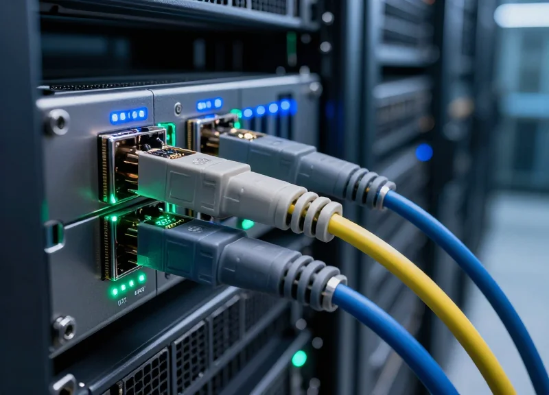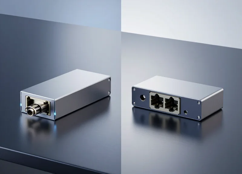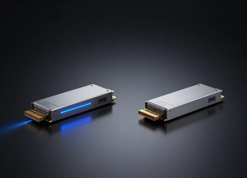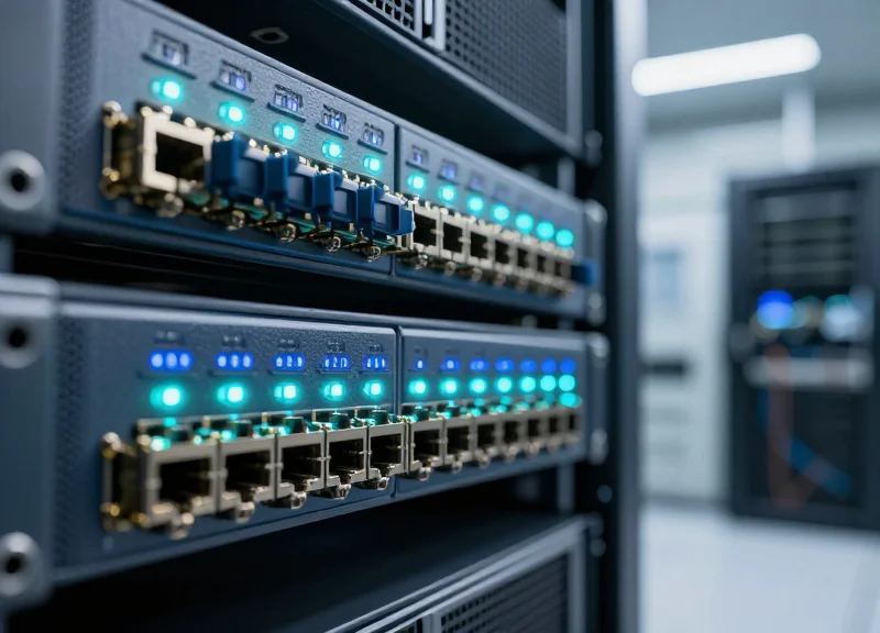
In an era where data consumption is growing exponentially, the backbone of the internet relies on robust Data Center Interconnect (DCI) technology. Ubytelink's 400G modules are engineered to solve the most pressing challenges of modern networking—latency, power consumption, and signal integrity—ensuring that global enterprises can scale without compromise.
The Strategic Shift to 400G DCI

The Strategic Shift to 400G DCI
The industry-wide migration from 100G to 400G DCI is driven by the urgent need to support hyper-scale architectures and data-intensive applications such as generative AI and machine learning. By quadrupling the capacity of a standard 100G link, 400G solutions allow data centers to process larger datasets with significantly improved power efficiency and a reduced physical footprint, effectively eliminating the bandwidth bottlenecks that hinder modern global networks.
Primary Drivers of 400G Adoption
The rapid evolution of cloud computing and the integration of AI into every layer of enterprise operations have fundamentally changed traffic patterns. Data centers are no longer isolated silos; they are interconnected nodes in a massive, high-speed ecosystem. The shift to 400G is catalyzed by the demand for lower latency in real-time analytics and the necessity for service providers to scale their backbone networks without incurring the prohibitive costs of laying additional dark fiber.
| Metric | 100G DCI Architecture | 400G DCI Architecture |
|---|---|---|
| Throughput Capacity | 100 Gbps per wavelength | 400 Gbps per wavelength |
| Power Consumption | Higher watts per Gigabit | ~40% reduction in watts per Gigabit |
| Port Density | Lower (Standard QSFP28) | Higher (QSFP-DD / OSFP) |
| Fiber Utilization | Baseline efficiency | 4x efficiency improvement |
| Cost Efficiency | Higher TCO at scale | Lower cost per bit transmitted |
Critical Considerations for the Transition
- Why is native 400G preferred over link aggregation of 100G?
While aggregating four 100G links can achieve 400G throughput, it increases cabling complexity, consumes more switch ports, and results in higher power consumption. A single 400G interface simplifies management and optimizes hardware utilization. - What role does AI play in this transition?
AI workloads require massive East-West traffic movement within and between data centers. 400G provides the necessary headroom to handle these bursts of data without creating latency spikes that could degrade model training performance. - How does 400G impact sustainability goals?
400G modules are designed with advanced silicon photonics that deliver better energy efficiency. By moving more data with less power, organizations can meet their ESG targets while expanding network capacity.
Ubytelink Engineering: Built for Mission-Critical Performance
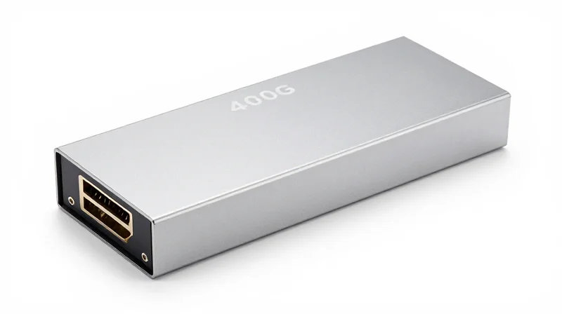
The Engineering Philosophy Behind Ubytelink's 400G Solutions
Ubytelink engineering is defined by a commitment to zero-compromise reliability, where every transceiver and interconnect is designed to exceed standard industry specifications through the use of high-grade photonics and advanced Digital Signal Processing (DSP). By prioritizing thermal management and signal integrity at the architectural level, Ubytelink ensures that 400G throughput remains consistent even under the most demanding thermal loads found in modern hyperscale data centers, effectively eliminating the performance bottlenecks common in lower-tier hardware.
Superior Component Architecture
At the heart of our 400G solutions lies a selection of premium silicon photonics and EML (Electro-absorption Modulated Laser) technology. Unlike generic alternatives that may cut costs on laser drivers or housing materials, Ubytelink utilizes components sourced from the world's most reputable semiconductor foundries, ensuring lower Bit Error Rates (BER) and extended Mean Time Between Failures (MTBF) for mission-critical deployments.
| Engineering Feature | Ubytelink Premium Standards | Generic 400G Solutions |
|---|---|---|
| Laser Source | High-stability EML / Silicon Photonics | Variable or Unbranded Optics |
| Heat Dissipation | Optimized Heat Sinks & Low-Power DSP | Standard Casing (Higher Thermal Stress) |
| Error Correction | Advanced FEC Optimization | Standard FEC Implementation |
| Lifecycle Testing | 100% Full-load Burn-in Testing | Sample-based Testing |
Validation Through Rigorous Stress Testing
Every Ubytelink 400G module undergoes a multi-stage validation process that includes high-temperature aging, mechanical vibration tests, and extensive interoperability checks across diverse switch and router platforms. This ensures that the transition from 100G to 400G is not just a jump in speed, but a significant improvement in network resilience and predictable performance for global service providers.
- How does Ubytelink ensure compatibility across different vendor environments?
We perform extensive EEPROM coding and physical layer testing on major vendor hardware to ensure seamless plug-and-play integration with Cisco, Arista, Juniper, and other leading platforms. - What measures are taken to prevent data degradation over long distances?
Our 400G DCI solutions utilize high-gain FEC and optimized optical power budgets to maintain signal clarity over fiber spans reaching up to 80km-120km for ZR and ZR+ applications. - How is thermal efficiency managed in high-density 400G ports?
Our modules are engineered with low-power-consumption DSPs and high-thermal-conductivity materials to keep operating temperatures well within safe limits even in fully populated 1U switches.
Optimizing Form Factors: QSFP-DD vs. OSFP
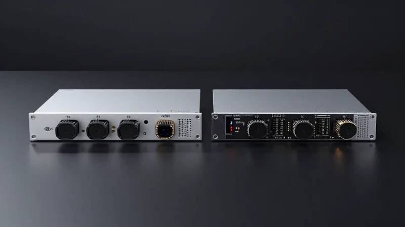
Choosing the Right Form Factor: QSFP-DD vs. OSFP
The choice between QSFP-DD and OSFP is a pivotal decision for data center architects, as it dictates thermal management efficiency, power headroom, and the long-term scalability of the 400G infrastructure.
Ubytelink addresses the diverse requirements of modern hyperscale environments by offering high-performance optics in both major form factors. While QSFP-DD (Quad Small Form-factor Pluggable Double Density) has become the industry favorite for its backward compatibility with legacy QSFP ports, OSFP (Octal Small Form-factor Pluggable) is engineered for higher power envelopes and provides a clearer path toward 800G and 1.6T transitions. Understanding these nuances ensures that network engineers can select Ubytelink solutions that maximize uptime and hardware longevity.
QSFP-DD: The Standard for High-Density Integration
The primary advantage of Ubytelink's QSFP-DD modules lies in their mechanical compatibility. By adding a second row of electrical pins, the QSFP-DD interface doubles the lane count from four to eight while maintaining the physical footprint of traditional QSFP28 modules. This allows network operators to use 400G ports for 100G or 200G legacy connections using simple breakout cables or adapters. For enterprises focused on maximizing port density in standard 1U or 2U rack configurations, QSFP-DD remains the most versatile and cost-effective choice.
OSFP: Superior Thermal Design for AI and Coherent Links
OSFP modules are slightly wider and deeper than the QSFP-DD standard, a design choice that facilitates an integrated heat sink directly on the module shell. This architectural difference significantly improves airflow and thermal dissipation, allowing OSFP modules to handle power loads of 15W to 30W. Ubytelink’s OSFP solutions are particularly effective for 400G ZR and ZR+ applications, where coherent digital signal processors (DSPs) generate substantial heat. By utilizing OSFP, data centers can maintain stable performance even under the heavy computational loads typical of AI training and massive cloud analytics.
| Feature | QSFP-DD (Ubytelink) | OSFP (Ubytelink) |
|---|---|---|
| Backward Compatibility | Excellent (Supports QSFP28/56) | Requires Adapter for QSFP |
| Thermal Management | Standard (Relies on system fan/cages) | Superior (Integrated Heat Sink) |
| Max Power Envelope | Up to 12W - 14W | Up to 15W - 30W |
| Main Use Case | Switching & General Networking | High-Power Coherent & AI Clusters |
| Roadmap Potential | Extends to 800G | Native design for 800G/1.6T |
Common Implementation Questions
- Can I use Ubytelink QSFP-DD modules in an OSFP port?
No, they are physically incompatible. However, OSFP-to-QSFP-DD adapters are available for specific hardware configurations, though native support is always recommended for mission-critical DCI links. - Which form factor is more reliable for 400G ZR/ZR+?
OSFP is often preferred for 400G ZR+ because its larger surface area and integrated heat sink better manage the high thermal output of coherent optics, reducing the risk of thermal throttling. - How does Ubytelink ensure signal integrity across different form factors?
Ubytelink utilizes high-grade PCB materials and precision-engineered gold-finger connectors for both QSFP-DD and OSFP to minimize Insertion Loss and Crosstalk, ensuring BER (Bit Error Rate) stays well below industry standards.
Energy Efficiency and Thermal Management

Energy Efficiency and Thermal Management
As data centers transition from 100G to 400G, the power density per rack increases exponentially, making energy efficiency and thermal management the primary determinants of network stability and longevity. Ubytelink addresses these challenges by utilizing low-power Digital Signal Processors (DSPs) and optimized optical engines that minimize heat generation at the source. By maintaining lower operating temperatures, Ubytelink modules not only safeguard signal integrity but also significantly extend the mean time between failures (MTBF) for both the optics and the interconnected switch hardware.
Precision Engineering for Heat Dissipation
Ubytelink’s 400G modules, particularly in the QSFP-DD and OSFP form factors, feature enhanced housing designs that maximize surface area for cooling. The integration of high-conductivity thermal interface materials (TIMs) ensures that heat is rapidly moved away from sensitive laser components, preventing wavelength drift and bit errors during peak traffic loads.
| Feature | Standard 400G Optics | Ubytelink 400G Solutions |
|---|---|---|
| Typical Power Consumption | 12W - 14W | 10W - 12W |
| Operating Temperature Range | 0°C to 70°C | -5°C to 75°C (Extended) |
| Thermal Design | Standard Zinc Alloy | High-Conductivity Integrated Fin Design |
| Cooling Efficiency | Standard Airflow | Optimized Low-Airflow Resistance |
Impact on Total Cost of Ownership (TCO)
Reducing power consumption by even 1.5 watts per module results in significant cumulative savings when scaled across thousands of ports in a global DCI environment. Lower heat output reduces the load on data center HVAC systems, directly lowering electricity bills and supporting corporate sustainability goals. Ubytelink's focus on efficiency ensures that network operators can maximize port density without exceeding their facility's thermal envelope.
- Why is heat dissipation more critical at 400G than 100G?
400G optics pack four times the bandwidth into similar footprints, leading to a massive increase in thermal density that can cause laser degradation if not managed through advanced materials. - How does Ubytelink's design improve hardware longevity?
By maintaining a stable and lower thermal profile, Ubytelink prevents 'thermal throttling' and reduces the mechanical stress on the host switch's power supply units and cooling fans. - Do lower power optics sacrifice signal performance?
No. Ubytelink utilizes state-of-the-art 7nm or 5nm DSP technology to achieve high-performance Forward Error Correction (FEC) with significantly lower power draw than legacy 16nm designs.
Signal Integrity and Low Latency Architecture
Signal Integrity and Low Latency Architecture
In the transition to 400G, the shift from NRZ to PAM4 modulation has made signal integrity and latency management the primary challenges of data center interconnects. Ubytelink addresses these hurdles by integrating high-performance Digital Signal Processing (DSP) and optimized Forward Error Correction (FEC) engines. Our architecture is designed to minimize the processing overhead associated with error correction, ensuring that data packets move at the speed of light with minimal digital friction, even across extended-reach fiber spans.
Advanced DSP: Precision for PAM4 Transmission
Ubytelink’s 400G transceivers leverage 7nm and 5nm DSP technologies to handle the complexities of Pulse Amplitude Modulation. Because PAM4 uses four amplitude levels, it is significantly more sensitive to noise and dispersion than previous generations. Our DSPs utilize adaptive equalization and sophisticated chromatic dispersion compensation to reconstruct signals in real-time. This allows for higher Bit Error Rate (BER) tolerance, which translates to a more stable and reliable link over long-haul DCI links without requiring frequent signal regeneration.
Reducing the 'Latency Tax' with Optimized FEC
While FEC is critical for maintaining data purity, it typically introduces a delay known as 'latency tax' due to the time required for parity checking and error correction. Ubytelink employs a specialized implementation of KP4 FEC and OpenFEC that prioritizes processing efficiency. By streamlining the algorithmic path within the silicon, we reduce the nanosecond latency of the transceiver, which is crucial for high-frequency trading, real-time AI processing, and distributed database synchronization.
| Feature | Industry Standard 400G | Ubytelink DCI Optimized |
|---|---|---|
| DSP Power Efficiency | Standard consumption | 15% Lower via 5nm nodes |
| FEC Latency (Approx.) | 120ns - 160ns | <100ns in Low-Latency modes |
| OSNR Tolerance | Moderate | Enhanced for Long-Reach Fiber |
| Signal Recovery | Basic Linear Equalization | Advanced Decision Feedback Equalization |
Frequently Asked Questions
- How does Ubytelink ensure signal purity over long distances?
We use high-gain FEC combined with advanced DSP equalization to compensate for Optical Signal-to-Noise Ratio (OSNR) penalties and fiber impairments. - Is the latency low enough for AI and Machine Learning workloads?
Yes, our optimized FEC engines are specifically designed to reduce processing time, making them ideal for the low-latency requirements of synchronized AI clusters. - Does Ubytelink support interoperability between different DSP vendors?
Our 400G modules follow CMIS and MSA standards, ensuring that our DSP-based signal processing is compatible with a wide range of third-party networking hardware.
Rigorous Testing Protocols for Global Reliability
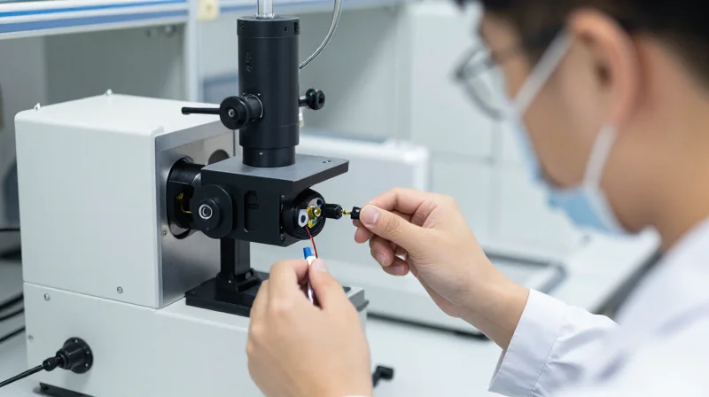
To meet the uncompromising demands of global hyperscale networks, Ubytelink 400G modules undergo a rigorous quality assurance cycle that simulates real-world stressors and extreme conditions. This protocol ensures that every transceiver maintains peak performance, low latency, and zero-loss signal integrity, regardless of the geographical or hardware environment in which it is deployed.
Comprehensive Performance Validation Framework
Every Ubytelink 400G DCI module passes through a tiered testing pipeline. This begins with component-level screening and culminates in end-to-end system validation. By utilizing state-of-the-art testing equipment from industry leaders like Anritsu and Keysight, Ubytelink can guarantee that its solutions exceed IEEE 802.3bs and MSA standards.
| Test Category | Key Parameters Measured | Objective |
|---|---|---|
| Environmental Stress | Temperature cycling (-40°C to +85°C), Humidity, Vibration | Ensuring structural integrity and performance in diverse climates. |
| Optical Integrity | Eye Diagram analysis, Bit Error Rate (BER), Wavelength accuracy | Validating signal clarity and reducing re-transmission needs. |
| Electrical & Power | Power consumption under load, EMI compliance, Voltage tolerance | Optimizing energy efficiency and preventing hardware interference. |
| Compatibility | Multi-vendor switch integration (Cisco, Arista, Juniper, etc.) | Guaranteeing seamless plug-and-play across diverse ecosystems. |
Interoperability and Long-Term Stability
A critical aspect of Ubytelink's testing protocol is 'Burn-in' testing. Modules are operated at maximum capacity under high-temperature conditions for extended periods to identify any potential early-life failures. This process dramatically increases the Mean Time Between Failures (MTBF), providing data center operators with the confidence that their interconnect fabric will remain stable for years to come.
Testing FAQ: Quality and Reliability
- How does Ubytelink ensure 400G modules work with existing hardware?
We maintain a comprehensive compatibility lab where modules are tested against a wide array of legacy and next-generation switches from major OEMs to ensure 100% EEPROM coding accuracy and link stability. - What is the standard for acceptable Bit Error Rate (BER) in your tests?
Ubytelink targets a pre-FEC (Forward Error Correction) BER that is significantly better than the industry standard, ensuring that the Post-FEC result is virtually error-free. - Are individual modules tested or just batches?
Unlike many manufacturers who perform random batch testing, Ubytelink performs 100% individual module testing for critical optical and electrical parameters before shipment.
Seamless Multi-Vendor Interoperability
Achieving True Hardware Agnosticism in 400G Networks
Ubytelink Data Center Interconnect (DCI) 400G Solutions are engineered to bypass the constraints of proprietary hardware ecosystems, offering plug-and-play compatibility across a vast spectrum of networking equipment. By adhering strictly to MSA (Multi-Source Agreement) standards and employing sophisticated firmware customization, Ubytelink ensures that its high-speed optical modules are recognized and optimized by controllers from major vendors like Cisco, Arista, Juniper, and NVIDIA (Mellanox). This interoperability is crucial for modern hyperscale and enterprise data centers that frequently employ a best-of-breed strategy, combining hardware from different manufacturers to optimize cost and performance without the risk of communication failures.
Precision EEPROM and Firmware Matching
The core of Ubytelink’s interoperability lies in its precision EEPROM (Electrically Erasable Programmable Read-Only Memory) coding process. Each module is programmed with vendor-specific identification codes and diagnostic parameters that allow it to pass stringent 'white-listing' checks during initialization. This eliminates the common 'Unsupported Transceiver' errors and ensures that advanced features like Digital Optical Monitoring (DOM) function correctly, providing real-time data on power levels, temperature, and voltage regardless of the host chassis. This level of detail allows network administrators to manage heterogeneous environments through a single pane of glass with consistent telemetry data.
| Manufacturer | Supported Device Series | Interoperability Status |
|---|---|---|
| Cisco | Nexus 9000/3000, Catalyst 9500 | Verified & Validated |
| Arista | 7060X, 7280R, 7800R3 Series | Verified & Validated |
| Juniper | PTX, QFX, MX Series | Verified & Validated |
| NVIDIA/Mellanox | Spectrum-2/3/4 Switches, ConnectX-6/7 | Verified & Validated |
| Generic MSA | Whitebox Switches (SONiC/ONIE) | Fully Compatible |
Interoperability and Deployment FAQ
- Will using Ubytelink 400G modules void my original equipment manufacturer (OEM) warranty?
No. In most jurisdictions, including the United States under the Magnuson-Moss Warranty Act, hardware manufacturers cannot void a warranty or refuse support simply because third-party components are used, provided those components do not cause direct damage to the system. - How does Ubytelink ensure compatibility with future firmware updates from vendors?
Ubytelink maintains an extensive R&D lab equipped with the latest hardware from major vendors. We proactively test new OS releases (such as Cisco NX-OS or Arista EOS) and update our module firmware via the Ubytelink cloud if adjustments are needed to maintain seamless communication. - Can Ubytelink modules coexist with OEM modules in the same switch?
Yes. Ubytelink 400G solutions are designed to be fully transparent to the switch fabric, allowing them to work side-by-side with original vendor optics in the same line card without port-to-port interference or protocol conflicts.
By prioritizing seamless multi-vendor interoperability, Ubytelink empowers organizations to reclaim control over their supply chain. This flexibility not only reduces lead times but also allows for significant cost savings without compromising the stability or visibility of the global 400G network infrastructure.
Future-Proofing Your Network for 800G and Beyond

Future-Proofing Your Network for 800G and Beyond
Implementing Ubytelink 400G solutions is a strategic investment that creates a scalable infrastructure path toward 800G by establishing the critical signaling, thermal management, and form-factor standards required for next-generation optical networking. Rather than a simple bandwidth increase, the shift to 400G introduces the PAM4 (Pulse Amplitude Modulation 4-level) architecture and high-density footprints that directly evolve into 800G and 1.6T specifications, ensuring that current hardware deployments remain compatible with the logical and electrical progressions of the future.
The Continuity of Form Factors and Signaling
The industry's move toward 800G relies heavily on the groundwork laid by 400G QSFP-DD and OSFP modules. Ubytelink’s 400G portfolio utilizes advanced 112G SerDes technology in later iterations, which is the same electrical interface used to power 800G systems. This commonality allows data center operators to maintain their existing cabling infrastructure and switch architectures while preparing for a 'pay-as-you-grow' expansion model.
| Network Metric | 400G Standard (Ubytelink) | 800G Evolution Path |
|---|---|---|
| Signaling Type | PAM4 (56G or 112G) | Enhanced PAM4 (112G+) |
| Module Interface | 8x50G or 4x100G Lanes | 8x100G or 4x200G Lanes |
| Form Factor | QSFP-DD / OSFP | QSFP-DD800 / OSFP800 |
| Power Efficiency | ~10-12W per module | Optimized Watt/Gbps density |
Common Transition Questions
- How does 400G deployment protect my current capital expenditure?
By adopting Ubytelink's 400G solutions, you are deploying hardware that supports backward compatibility with 100G/200G while sharing the same management interfaces (CMIS) used in 800G, reducing future training and integration costs. - Will I need to replace my fiber plant when moving from 400G to 800G?
In most cases, no. Ubytelink 400G solutions are optimized for standard G.652 Single-Mode Fiber (SMF), which remains the primary medium for 800G-DR8 and 800G-2xFR4 specifications. - What role does Ubytelink play in ensuring 800G readiness?
Ubytelink focuses on low-power DSP designs and superior thermal dissipation in our 400G modules, addressing the two biggest hurdles in 800G migration—heat management and energy consumption.
As global data traffic continues its exponential climb, the ability to transition smoothly between generations of optical technology is a competitive necessity. Ubytelink’s commitment to premium components and standards-based engineering ensures that your network is not just ready for the demands of today, but is built on a foundation that makes the leap to 800G an incremental upgrade rather than a total system overhaul.
Ubytelink is committed to providing the cutting-edge optical technology necessary to power the world's most demanding data environments. By choosing our 400G DCI solutions, you are investing in a future of unparalleled connectivity and performance. Contact our technical sales team today to request a quote or a demo for your next infrastructure upgrade.