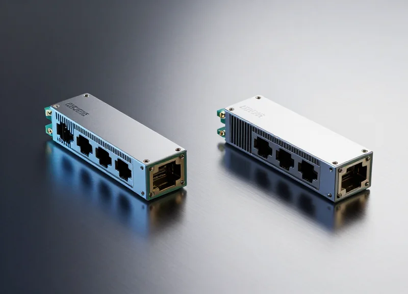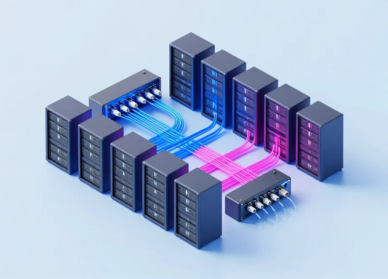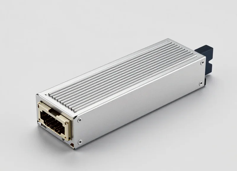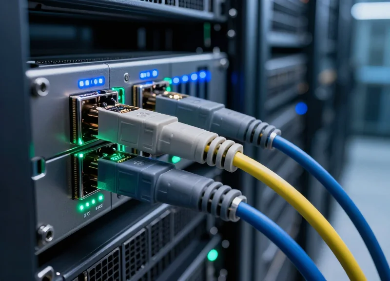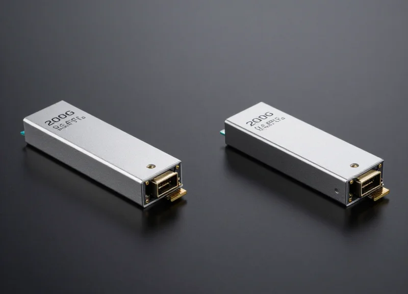
As hyperscale data centers and enterprise networks push beyond the limits of 100G, the 200G QSFP56 ER4 has emerged as a critical standard for long-reach connectivity. However, choosing between 200G and burgeoning 400G solutions—or sticking with dual 100G paths—requires a sophisticated understanding of performance trade-offs. This article provides a veteran engineer's perspective on how the 200G QSFP56 ER4 stands up against its peers in the current market.
The Architecture of 200G QSFP56 ER4

The Architecture of 200G QSFP56 ER4
The 200G QSFP56 ER4 architecture is defined by its ability to aggregate four lanes of 50Gbps PAM4 signals into a single 200Gbps optical stream, utilizing a LAN-WDM (LWDM) wavelength multiplexing scheme to achieve a 40km transmission distance without the requirement for optical amplifiers.
PAM4 Modulation and Signal Integrity
At the heart of the QSFP56 ER4 is Pulse Amplitude Modulation 4-level (PAM4) technology. By operating at 26.5625 GBaud per lane, PAM4 allows each lane to carry two bits of information per clock cycle, effectively doubling the capacity of previous NRZ-based systems. To manage the inherent Signal-to-Noise Ratio (SNR) degradation associated with four-level signaling, the module incorporates an internal Digital Signal Processor (DSP) and relies on Host KP4 FEC (Forward Error Correction) to maintain link integrity over long distances.
LAN-WDM Wavelength Mapping
| Channel | Wavelength (nm) | Center Frequency (THz) |
|---|---|---|
| L0 | 1295.56 | 231.4 |
| L1 | 1300.05 | 230.6 |
| L2 | 1304.58 | 229.8 |
| L3 | 1309.14 | 229.0 |
The choice of the LWDM grid is strategic for the 40km target. By positioning the four wavelengths in the O-band near the zero-dispersion point of standard Single-Mode Fiber (SMF), the architecture minimizes chromatic dispersion. This high-precision wavelength spacing requires cooled Electro-absorption Modulated Lasers (EML) to prevent frequency drift, ensuring consistent performance across varying thermal environments.
Optical Components: EML and APD
To achieve the 18dB loss budget required for 40km spans, the Transmit Optical Sub-Assembly (TOSA) utilizes high-power EMLs. On the receiving end, the Receiver Optical Sub-Assembly (ROSA) employs an Avalanche Photodiode (APD) instead of a standard PIN photodiode. The APD provides internal gain, significantly increasing receiver sensitivity, which is the primary factor allowing the ER4 to function without external Erbium-Doped Fiber Amplifiers (EDFAs).
- Why does 200G ER4 use LWDM instead of CWDM?
LWDM offers narrower spacing and operates closer to the zero-dispersion wavelength of SMF, which is necessary to mitigate dispersion penalties over 40km that would be too severe for CWDM wavelengths. - Is the 200G ER4 backward compatible with QSFP28?
While the physical form factor is similar, the QSFP56 ER4 uses PAM4 modulation, whereas most QSFP28 modules use NRZ; therefore, they are not interoperable unless the equipment specifically supports multi-rate modulation. - What is the power consumption of this architecture?
The inclusion of cooled EML lasers and a high-performance DSP typically results in a power consumption of approximately 7W to 7.5W, which is higher than shorter-reach SR4 or FR4 modules.
Head-to-Head: 200G QSFP56 ER4 vs. 100G ER4/eER4
Head-to-Head: 200G QSFP56 ER4 vs. 100G ER4/eER4
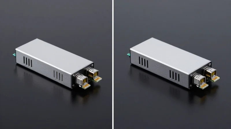
The shift from 100G ER4 to 200G QSFP56 ER4 represents a critical evolution in optical networking, doubling data throughput within the same physical footprint by transitioning from 25G NRZ to 50G PAM4 signaling. While legacy 100G ER4 solutions have been the backbone of 40km reach applications for years, the 200G QSFP56 ER4 provides the necessary density and cost-per-bit advantages required for modern data center interconnects (DCI) and metro-access aggregation.
Signaling Evolution: NRZ vs. PAM4
The most significant technical distinction lies in the modulation format. 100G ER4 utilizes Non-Return to Zero (NRZ) signaling, where each clock cycle carries a single bit. In contrast, 200G QSFP56 ER4 employs 4-level Pulse Amplitude Modulation (PAM4), which encodes two bits per symbol. This allows the 200G module to reach 212.5 Gbps using four optical lanes (4x50G) without requiring additional fibers or a larger chassis. However, PAM4 is more susceptible to noise, making the integration of Forward Error Correction (FEC) on the host equipment essential for maintaining a bit error rate (BER) suitable for 40km transmission.
| Feature | 100G ER4 / eER4 | 200G QSFP56 ER4 |
|---|---|---|
| Data Rate | 103.1 Gbps | 212.5 Gbps |
| Modulation | NRZ (Non-Return to Zero) | PAM4 (Pulse Amplitude Modulation) |
| Electrical Interface | 4x 25G NRZ | 4x 50G PAM4 |
| Wavelength Grid | LWDM4 (1295-1309nm) | LWDM4 (1295-1309nm) |
| Max Reach | 40km (ER4) / 30km (eER4) | 40km (with Host FEC) |
| Power Consumption | Typical 3.5W - 4.5W | Typical 6.5W - 7.5W |
Bandwidth Density and Infrastructure ROI
By leveraging the same QSFP form factor, 200G ER4 allows operators to double their capacity per rack unit compared to 100G ER4. This is particularly valuable in space-constrained colocation facilities. While the power consumption per module is higher for 200G, the power-per-gigabit ratio is significantly lower, leading to improved thermal efficiency and lower long-term operational expenditure (OPEX). Transitioning to 200G ER4 also simplifies the migration path toward 400G and 800G by establishing a PAM4-ready infrastructure.
- Are 100G ER4 and 200G ER4 modules interoperable?
No. Due to the different modulation schemes (NRZ vs. PAM4) and the difference in baud rates, these modules cannot communicate with each other directly. - Is host-side FEC mandatory for 200G ER4?
Yes, unlike most 100G ER4 implementations that can run without FEC, 200G QSFP56 ER4 relies on IEEE 802.3bs standard FEC (KP4) to achieve its rated 40km distance. - How does the cost compare between the two?
While 200G modules have a higher initial unit price, the cost per gigabit is lower, and the savings in port density often result in a lower Total Cost of Ownership (TCO) for new deployments.
Latency Analysis in High-Frequency Environments

Latency Dynamics: The PAM4 DSP Penalty
In high-frequency trading (HFT) and ultra-low latency (ULL) environments, the transition from 100G NRZ to 200G PAM4 modulation introduces a significant architectural shift: the integration of a Digital Signal Processor (DSP). Unlike legacy 100G ER4 modules that often utilized simpler analog clock and data recovery (CDR) chips with near-zero processing delay, the 200G QSFP56 ER4 relies on a DSP to manage the complexities of four-level pulse amplitude modulation. This DSP performs tasks such as equalization and chromatic dispersion compensation, which are essential for 40km reach but add measurable nanoseconds of 'glass-to-glass' latency that can impact competitive execution in financial markets.
The Role of Forward Error Correction (FEC)
The primary source of latency in 200G ER4 links is not the optical medium itself, but the mandatory Forward Error Correction (FEC) required by the PAM4 standard. Because PAM4 signaling has a lower signal-to-noise ratio (SNR) than NRZ, it is inherently more prone to bit errors. To achieve an error-free performance level suitable for data transmission (typically a BER < 1E-12), the KP4 FEC algorithm is employed on the host side or within the module. This process involves grouping data into blocks, adding parity bits, and performing complex mathematical checks at the receiver, typically introducing 100ns to 150ns of delay per link segment.
| Module Type | Modulation | FEC Requirement | Typical Latency (One-Way) |
|---|---|---|---|
| 100G ER4 | NRZ | Optional / None | < 10 ns |
| 200G QSFP56 ER4 | PAM4 | Mandatory (KP4) | 100 - 200 ns |
| 200G QSFP-DD (Alt) | PAM4 | Mandatory (KP4) | 110 - 250 ns |
Impact on Real-Time Computing and Financial Services
For financial services, the shift to 200G ER4 requires a re-evaluation of the 'speed vs. density' trade-off. While 200G offers double the throughput of 100G in the same footprint, the cumulative latency across multiple switch hops can become a bottleneck for latency-sensitive applications like algorithmic trading or high-performance compute clusters. Architects must account for the deterministic nature of DSP processing and the potential for jitter introduced by FEC re-transmissions or error-correction cycles. In scenarios where every nanosecond counts, sticking to 100G NRZ for 40km reach may still be preferable despite the lower density.
- Does the 200G QSFP56 ER4 support 'FEC-off' mode?
No, standard 200G QSFP56 ER4 modules require KP4 FEC to function correctly over 40km distances; running without FEC would result in an unusable bit error rate. - How does DSP latency compare across different vendors?
While most follow IEEE standards, some vendors optimize DSP firmware for 'Low Latency' modes that reduce processing cycles, though often at a slight cost to reach or power consumption. - Is there a significant latency difference between QSFP56 and QSFP-DD 200G modules?
The latency is primarily driven by the DSP and FEC algorithm rather than the form factor; however, QSFP56 is often slightly more efficient in thermal management, which can lead to more stable DSP performance.
Power Consumption and Thermal Management
Power Consumption and Thermal Management
The 200G QSFP56 ER4 module represents a significant leap in power efficiency, delivering a 20-30% reduction in wattage per gigabit compared to stacking multiple 100G ER4 links. While the introduction of the Digital Signal Processor (DSP) required for PAM4 signaling increases the base power consumption of a single module, the ability to consolidate bandwidth into a single port significantly lowers the total energy overhead and cooling requirements for the data center fabric.
Efficiency Metrics: Wattage per Gigabit
In long-reach 40km applications, power consumption is dominated by the laser drivers and the DSP. When comparing the 200G QSFP56 ER4 to the older 100G ER4 standards, the efficiency gains become clear. A single 100G ER4 module typically consumes between 3.5W and 4.5W. To achieve 200G throughput using legacy hardware, an operator would need two such modules, totaling approximately 9W. In contrast, a 200G QSFP56 ER4 module typically operates within a 7W to 7.5W power envelope.
| Module Type | Typical Power (W) | Max Power (W) | Wattage per Gbps |
|---|---|---|---|
| 100G QSFP28 ER4 | 4.5W | 5.0W | 0.045W |
| 2x 100G QSFP28 ER4 | 9.0W | 10.0W | 0.045W |
| 200G QSFP56 ER4 | 7.0W | 7.5W | 0.035W |
| 400G QSFP-DD ER4 (Early) | 14.0W | 16.0W | 0.035W |
The shift from 0.045W per Gbps in the 100G era to 0.035W in the 200G era allows for higher port density without exceeding the thermal limits of standard 1U switch chassis. Furthermore, while 400G modules achieve similar efficiency ratios, they often require advanced cooling solutions or liquid cooling in high-density deployments due to the concentrated heat of a 14W+ module.
Thermal Challenges with PAM4 DSPs
Despite the efficiency gains, the 200G QSFP56 ER4 introduces localized thermal challenges. Unlike the NRZ-based 100G modules that used simpler Clock and Data Recovery (CDR) circuits, the PAM4 DSP generates concentrated heat within the module housing. This requires sophisticated heat sink designs and optimized airflow management. Network architects must ensure that the switch's cooling capacity can handle the 7.5W per port load across all populated slots to prevent thermal throttling of the DSP, which can lead to increased bit error rates (BER).
Operational Efficiency FAQ
- Does 200G QSFP56 ER4 require specialized cooling?
No, it is designed for standard air-cooled environments, but it requires consistent front-to-back or back-to-front airflow to maintain the DSP temperature within the case limit (typically 0°C to 70°C). - How does power consumption affect the total cost of ownership (TCO)?
Reduced wattage per gigabit directly lowers electricity costs and reduces the demand on the Uninterruptible Power Supply (UPS) and cooling infrastructure, leading to a lower TCO over the 5-year lifecycle of the hardware. - Is the power consumption stable over the 40km reach?
Yes, the power consumption remains relatively constant regardless of fiber distance, as the laser and DSP operate at fixed power levels to ensure signal integrity across the 18dB power budget.
Total Cost of Ownership (TCO) Breakdown

Total Cost of Ownership (TCO) Breakdown
The Total Cost of Ownership for 200G QSFP56 ER4 modules is defined by a strategic balance between moderate initial capital expenditure and significant operational savings achieved through port density and power efficiency. While 400G optics often command a premium for bleeding-edge performance and 100G solutions suffer from high per-gigabit operational overhead, the 200G ER4 standard serves as a financial 'sweet spot' for enterprises seeking to double bandwidth without a linear increase in power or cooling costs.
CAPEX: Hardware and Infrastructure Integration
Capital expenditure for 200G ER4 deployments includes the transceiver unit price, switch port costs, and potential fiber infrastructure upgrades. Because QSFP56 utilizes the same form factor as QSFP28, many existing high-density chassis can support 200G upgrades with minimal hardware replacement. This backward compatibility significantly lowers the 'barrier to entry' compared to transitioning to OSFP or QSFP-DD formats required for 400G, which often necessitate a complete forklift upgrade of the switching fabric.
OPEX: Power, Cooling, and Maintenance
Operational expenditure is where the 200G QSFP56 ER4 demonstrates its true value. By utilizing PAM4 signaling to deliver 200G over four lanes, these modules typically consume between 7W and 7.5W. When compared to the power required to run two 100G ER4 modules (which can exceed 10W combined), the 200G solution offers a 25-30% reduction in power consumption per gigabit. Over a 3-5 year span, these savings compound as cooling requirements for data center racks are proportionally reduced.
| Metric (per 200G Link) | 2x 100G QSFP28 ER4 | 1x 200G QSFP56 ER4 | 1x 400G QSFP-DD ER4 (Split) |
|---|---|---|---|
| Avg. Power Consumption | ~10.5W | ~7.5W | ~12W - 14W |
| Port Density Usage | 2 Ports | 1 Port | 0.5 Port |
| Relative CAPEX (Est.) | Low | Medium | High |
| 3-Year Energy Cost | Highest | Lowest | Moderate |
Long-term Financial Impact FAQ
- Is 200G ER4 more cost-effective than 400G ER4?
In the short term (1-3 years), yes. 200G ER4 uses more mature laser technology and does not require the expensive infrastructure upgrades associated with 400G, leading to a faster Return on Investment (ROI) for mid-tier data centers. - How does 200G ER4 affect rack cooling budgets?
By consolidating two 100G links into a single 200G module, thermal output is localized and reduced by roughly 3W per link, allowing for higher density per rack without exceeding thermal thresholds. - What is the expected lifespan for TCO calculations?
Most financial models for 200G deployment assume a 5-year lifecycle. During this period, the savings in energy and port availability typically offset the higher initial cost of 200G PAM4 hardware compared to legacy 100G NRZ hardware.
Comparison with 400G LR4 and ER4 Alternatives
Strategic Positioning: 200G ER4 vs. 400G LR4 and ER4
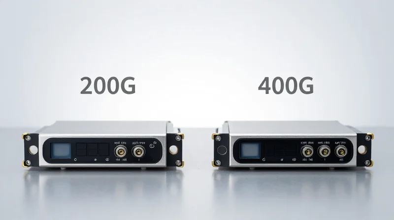
Choosing between 200G QSFP56 ER4 and 400G alternatives depends primarily on whether an organization prioritizes incremental bandwidth expansion or a full-scale infrastructure leap. While 400G modules offer double the capacity, 200G ER4 remains the more pragmatic choice for service providers operating within established QSFP56 thermal and power envelopes. It provides a stable 40km reach without the extreme cooling requirements or the significant CapEx of 400G-native switching fabrics, effectively serving as a bridge for networks that are not yet ready for the 800G transition path.
Comparative Technical Specifications
| Specification | 200G QSFP56 ER4 | 400G QSFP-DD LR4 | 400G QSFP-DD ER4 |
|---|---|---|---|
| Reach | 40km | 10km | 40km |
| Form Factor | QSFP56 | QSFP-DD | QSFP-DD |
| Typical Power Consumption | 7.0W - 7.5W | 10W - 12W | 14W - 16W |
| Lane Rate | 4x50G PAM4 | 4x100G PAM4 | 4x100G PAM4 |
| Cooling Requirement | Moderate | High | Very High |
The Scalability Trade-off
The 400G LR4 is a 10km solution and is not a direct competitor for distance, yet it is often considered for high-density campus environments. In contrast, the 400G ER4 directly competes with 200G ER4 at the 40km range. However, the 400G ER4 often requires EML lasers with complex optical amplification or sophisticated DSPs that drive up both the cost per unit and the failure risk due to heat. For operators managing legacy fiber plants where port density is less critical than power efficiency, the 200G ER4 offers a superior 'sweet spot' for total cost of ownership over a 3-year cycle.
Deployment Considerations and FAQs
- Is 400G ER4 a viable alternative to 200G ER4 for regional links?
While viable for raw capacity, 400G ER4 is significantly more expensive and draws nearly double the power. It is only recommended if fiber exhaustion is the primary constraint. - Can 200G QSFP56 ER4 work in 400G ports?
Most QSFP-DD ports are backward compatible with QSFP56, allowing for the use of 200G ER4 in newer hardware to save on costs while maintaining long-reach connectivity. - Which module is more future-proof?
400G is more future-proof as the industry aligns with 800G and 1.6T standards; however, 200G ER4 is more cost-effective for current 40km link requirements where 400G bandwidth is not yet fully utilized.
The Impact of Forward Error Correction (FEC)

The Essential Role of KP4 FEC in 200G QSFP56 ER4
Forward Error Correction (FEC) is not merely an optional feature for 200G QSFP56 ER4; it is a fundamental requirement of the IEEE 802.3bs and 802.3cd standards necessary to maintain a Bit Error Ratio (BER) below 1E-13. By utilizing the KP4 (RS(544,514)) algorithm, 200G modules can compensate for signal degradation over 40km of fiber, effectively allowing the system to operate even when the raw 'pre-FEC' signal contains errors that would otherwise lead to total packet loss in legacy 100G systems.
Performance Impact: Latency vs. Reliability
While KP4 FEC provides the coding gain required for long-distance 200G transmission using PAM4 modulation, it introduces a processing delay. This latency, typically ranging from 100ns to 150ns per link, is a critical consideration for ultra-low-latency applications such as high-frequency trading (HFT) or real-time industrial compute. However, for the vast majority of enterprise data centers and service provider backhauls, the reliability gains—specifically the ability to recover from burst errors caused by fiber impurities—far outweigh the negligible increase in round-trip time.
| Feature | 100G ER4 (NRZ) | 200G QSFP56 ER4 (PAM4) |
|---|---|---|
| FEC Requirement | Optional/None | Mandatory (KP4) |
| Standard BER Target | 1E-12 (Raw) | 1E-13 (Post-FEC) |
| Link Latency | Low (No FEC processing) | Moderate (~100-150ns) |
| Error Correction Gain | Minimal | High (Essential for 40km) |
Interoperability and Host System Support
The primary challenge when deploying 200G QSFP56 ER4 is ensuring that the host switch or router silicon supports the KP4 FEC algorithm at the physical port level. Unlike 100G modules where FEC was often optional or utilized simpler RS-FEC (528, 514), 200G PAM4 modulation requires the more robust KP4 version. Misconfiguration—where one end has FEC enabled and the other disabled—will result in a 'link-down' state or a high CRC error count, making standardized configuration management essential across multivendor environments.
- Can 200G QSFP56 ER4 run without FEC?
No. The signal-to-noise ratio requirements for PAM4 modulation at 200G speeds mean the link will not achieve stability or meet IEEE standards without active KP4 FEC. - Does FEC impact the power consumption of the 200G module?
Yes. The computational overhead of the FEC engine within the DSP increases the power draw of the module compared to non-FEC optics, typically contributing to the 4.5W to 5.5W thermal profile of QSFP56 ER4. - Is KP4 FEC compatible with all 200G switches?
Most modern QSFP56-compliant switches support KP4 FEC, but older 100G/200G hybrid platforms may require firmware updates or specific port configurations to enable the 802.3bs sublayer.
Supply Chain and Availability: The Practical Factor
The 200G QSFP56 ER4 ecosystem currently represents a mature, highly available middle ground that avoids the supply chain volatility often associated with cutting-edge 400G optics. While 400G is the strategic direction for hyperscalers, the 200G supply chain offers greater vendor diversity and shorter lead times for enterprise and service provider networks requiring immediate 40km reach capabilities.
Market Maturity and Component Stability
The manufacturing process for 200G QSFP56 ER4 has reached a plateau of stability. Since it utilizes established PAM4 modulation and refined laser packaging techniques, yield rates are consistently high across multiple tier-1 and tier-2 manufacturers. In contrast, 400G ER4 modules rely on more complex EML (Electro-absorption Modulated Laser) arrays and sophisticated DSP (Digital Signal Processing) chips that are frequently subject to allocation or supply constraints due to high demand in the AI and cloud sectors.
| Supply Chain Metric | 200G QSFP56 ER4 | 400G ER4/LR4 Alternatives |
|---|---|---|
| Average Lead Time | 2 to 6 weeks | 12 to 24+ weeks |
| Manufacturing Yield | High (Mature) | Moderate (Scaling) |
| Vendor Availability | Widespread (Third-party & OEM) | Concentrated (Primarily Tier-1) |
| Component Risk | Low (Standardized PAM4/DSP) | High (Advanced DSP & High-Power Lasers) |
Legacy Integration and Procurement Flexibility
Choosing the 200G QSFP56 ER4 allows procurement teams to leverage a broader base of suppliers. This competition keeps pricing aggressive and provides a safety net if a primary vendor faces localized shipping delays. Furthermore, because 200G QSFP56 is backward compatible with many QSFP-based switch ports in terms of physical form factor, it eliminates the need for the specialized adapters or complex cabling transitions sometimes required when integrating early-generation 400G hardware into existing environments.
Practical Procurement FAQ
- Are 200G optics easier to source from third-party vendors?
Yes. The coding and compatibility profiles for 200G QSFP56 are well-documented, making third-party modules highly reliable and readily available compared to 400G versions. - How do global chip shortages affect 200G vs 400G?
200G modules typically use older-generation DSPs which are not currently the primary target of high-end manufacturing bottlenecks, whereas 400G components compete for capacity with 800G and AI-specific silicon. - Is there a risk of 200G being discontinued soon?
While 400G is growing, 200G remains a standard part of the roadmap for the next 3-5 years, ensuring that replacement parts and expansion modules will remain in the supply chain for the foreseeable future.
In conclusion, the 200G QSFP56 ER4 offers a compelling balance of reach, power efficiency, and cost-per-bit for networks not yet ready to commit to the high thermal demands of 400G. By analyzing your specific latency requirements and long-term TCO, you can determine if this standard is your ideal path forward. Contact our technical team today for a customized network assessment and hardware quote.