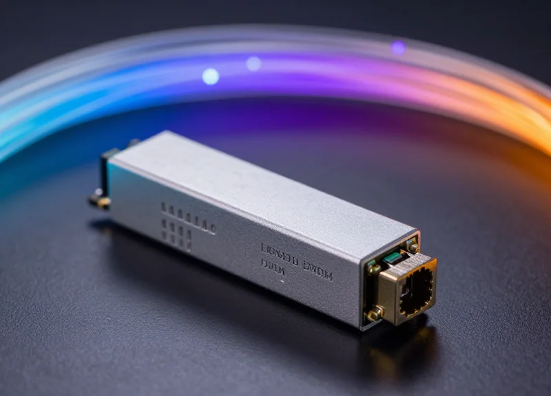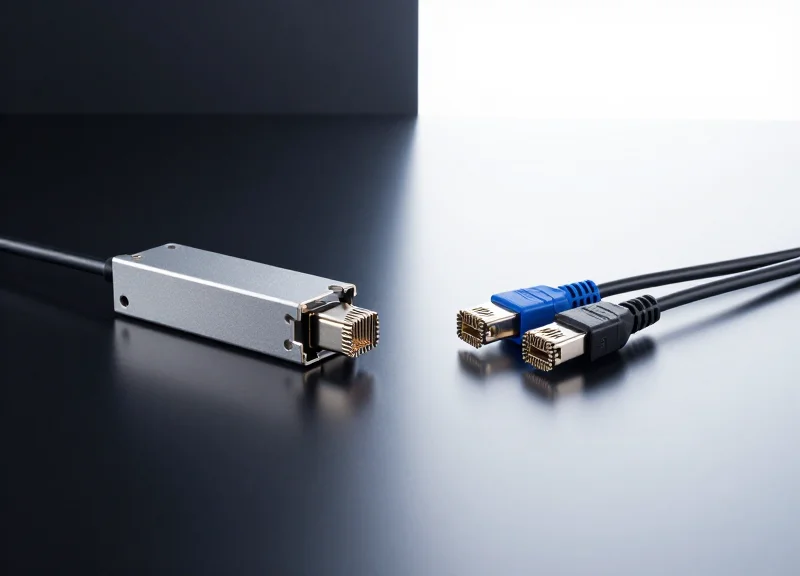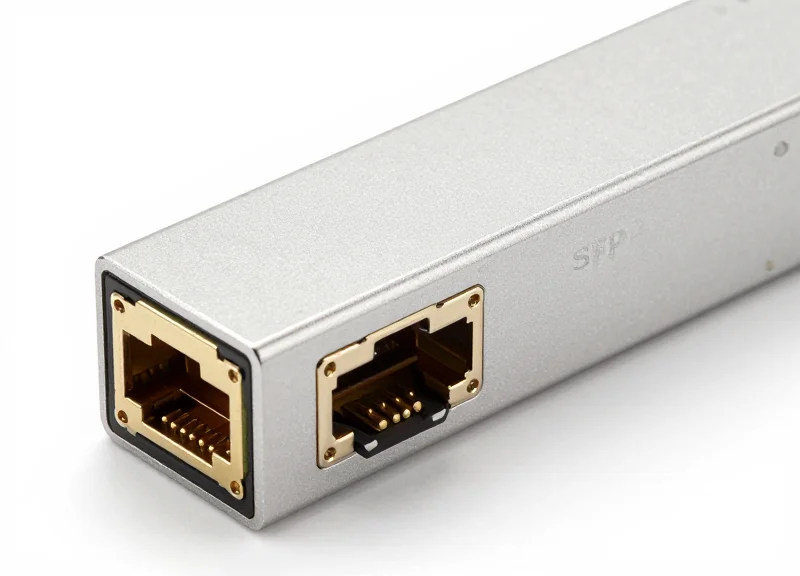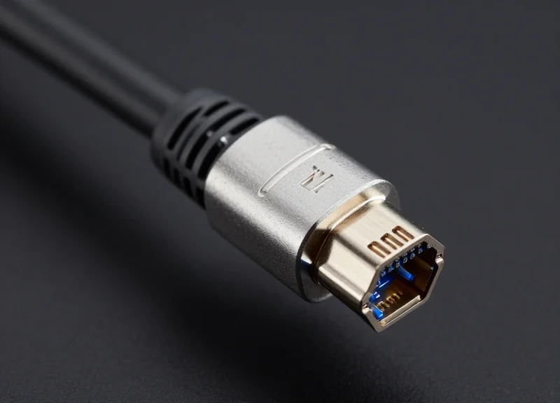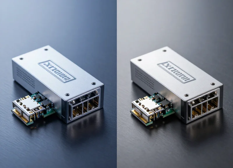
As hyperscale data centers transition to 200G and 400G architectures, the choice between optical form factors becomes a pivot point for operational efficiency. This article evaluates 200G FR4 solutions against industry alternatives to help architects balance bandwidth demands with fiscal and thermal constraints.
The Rise of 200G FR4 in Modern Networking
The Rise of 200G FR4 in Modern Networking
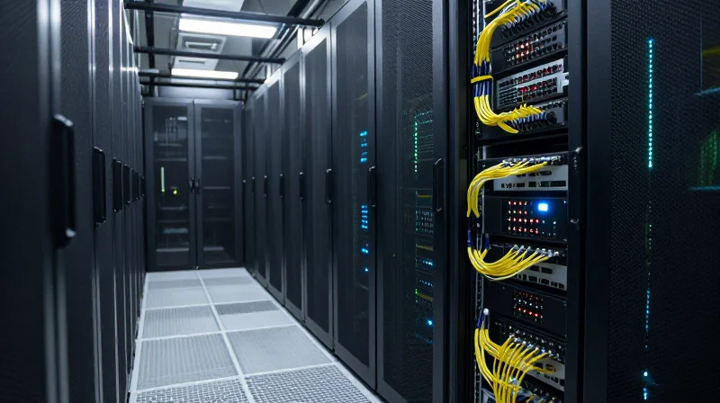
200G FR4 has emerged as a cornerstone of modern high-speed networking, providing a critical balance of reach, power efficiency, and cost for intra-data center interconnects up to 2km. By leveraging the Coarse Wavelength Division Multiplexing (CWDM) grid and advanced PAM4 modulation, 200G FR4 allows operators to double the bandwidth of traditional 100G CWDM4 links while maintaining the same physical fiber infrastructure.
The Technological Evolution: From CWDM4 to FR4
The shift from 100G to 200G was driven by the need for higher spectral efficiency without the complexity of increasing fiber counts. 200G FR4 utilizes four wavelengths (1271, 1291, 1311, and 1331nm) with each wavelength carrying a 50Gbps PAM4 signal. This represents a departure from the 25Gbps NRZ signals used in 100G CWDM4, effectively doubling the data rate per lane and facilitating a smoother migration path for hyperscale data centers transitioning toward 400G and 800G architectures.
| Feature | 100G CWDM4 | 200G FR4 |
|---|---|---|
| Modulation | NRZ | PAM4 |
| Lane Rate | 25 Gbps | 50 Gbps |
| Number of Lanes | 4 | 4 |
| Reach | 2 km | 2 km |
| Fiber Type | Single-Mode (SMF) | Single-Mode (SMF) |
Key Drivers for 200G FR4 Adoption
- Why is 200G FR4 preferred over SR4 for mid-reach applications?
While SR4 is cost-effective for very short distances using multi-mode fiber (typically <100m), 200G FR4 uses single-mode fiber to support the 2km reach required for leaf-spine connections in large-scale facilities without the signal degradation inherent in multi-mode solutions. - How does it optimize total cost of ownership (TCO)?
By using only four lasers and staying within the 2km reach specification, 200G FR4 avoids the higher costs and tighter tolerances required for LR (Long Reach) modules, which are designed for 10km and use more expensive cooling and precision optics. - What role does PAM4 play in its rise?
PAM4 modulation is the enabler for higher throughput. By transmitting two bits per symbol, it allows 200G FR4 to achieve higher speeds using existing optical components designed for lower baud rates, keeping complexity and heat dissipation manageable.
As hyperscale deployments continue to expand, the 2km 'FR' reach has become the standard sweet spot. 200G FR4 provides a reliable, interoperable solution that bridges the gap between legacy 100G systems and the high-density requirements of future-proofed networks, ensuring that bandwidth growth does not outpace economic or thermal budgets.
Technical Deep Dive: FR4 vs. DR4 Architectures
Technical Deep Dive: FR4 vs. DR4 Architectures
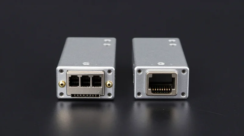
The fundamental difference between 200G FR4 and 200G DR4 lies in the spatial and spectral utilization of the optical fiber. 200G FR4 employs Coarse Wavelength Division Multiplexing (CWDM) to combine four 50G PAM4 signals onto a single pair of single-mode fibers (SMF), whereas 200G DR4 uses four parallel fiber pairs to transmit the same data volume. This architectural choice dictates the transceiver's internal complexity, the required cabling density, and the ultimate distance the signal can travel without significant degradation.
| Feature | 200G FR4 (CWDM4) | 200G DR4 (Parallel) |
|---|---|---|
| Wavelengths | 4 (1271, 1291, 1311, 1331nm) | 1 (1310nm) |
| Total Fibers | 2 (1 Duplex Pair) | 8 (4 Duplex Pairs) |
| Connector Type | LC Duplex | MPO-12 / MTP |
| Maximum Reach | 2 km | 500 m (standard) |
| Internal Optics | Requires MUX/DEMUX | No Multiplexing required |
Cabling Density and Infrastructure Implications
From an infrastructure standpoint, 200G FR4 is highly efficient for long-reach applications within the data center, such as leaf-to-spine links. By using only two fibers per link, it maximizes existing LC-based patch panels and minimizes the physical bulk in cable trays. Conversely, 200G DR4 requires a 4-fold increase in fiber count. While DR4 transceivers often have a lower unit cost because they omit the expensive optical multiplexer and demultiplexer components, the 'hidden' costs of high-density MPO cabling and the associated cable management frequently make FR4 the more economical choice for reaches beyond the immediate rack.
Architectural FAQ
- Can 200G DR4 support breakout applications?
Yes. Because DR4 uses parallel fibers for each 50G lane, it can be easily broken out into four independent 50G-DR links using an MPO-to-LC breakout cable. FR4 cannot do this natively because its lanes are multiplexed onto a single fiber. - Why is FR4 better suited for 2km reaches?
FR4 is specifically designed with tighter optical specifications and CWDM technology to handle the dispersion and attenuation challenges of longer distances, whereas DR4 is optimized for short-reach, high-volume parallel connections. - Does DR4 offer lower latency than FR4?
The latency difference is negligible. While FR4 has the added step of optical multiplexing, the time added is in the picosecond range, which does not impact standard Ethernet networking performance.
Latency Benchmarking: Signal Integrity at Speed

The Latency Impact of PAM4 and DSP in 200G FR4
The primary latency differentiator in 200G FR4 modules is the integration of Digital Signal Processing (DSP) required to manage PAM4 (4-Level Pulse Amplitude Modulation) signaling. Unlike legacy NRZ (Non-Return to Zero) systems that utilize simple 'on-off' keying with minimal processing, 200G FR4 relies on DSPs to perform equalization and Forward Error Correction (FEC) to overcome the signal-to-noise ratio (SNR) penalties inherent in multi-level signaling. This adds a predictable but measurable latency—typically ranging from 100ns to 250ns—which is essential for maintaining signal integrity over 2km reaches but represents a trade-off for ultra-low-latency environments.
Comparative Latency Performance Metrics
| Technology | Modulation Type | Processing Requirement | Typical Latency (ns) |
|---|---|---|---|
| 200G FR4 | PAM4 | DSP with FEC | 100 - 250 ns |
| 200G DR4 | PAM4 | DSP with FEC | 100 - 250 ns |
| 100G LR4 (Legacy) | NRZ | Analog CDR | < 5 ns |
| 200G LPO (Emerging) | PAM4 | No DSP (Direct Drive) | < 2 ns |
While the absolute latency of 200G FR4 is higher than analog NRZ solutions, it is important to note that the DSP-based approach provides superior robust signal integrity. The DSP compensates for chromatic dispersion and inter-symbol interference (ISI) that occur as light travels through the 2km of single-mode fiber. Without this processing, 200G data rates would be unachievable over standard CWDM grids due to the closure of the 'eye' in PAM4 signaling. Therefore, the latency 'cost' is effectively the price of the bandwidth density provided by FR4.
Signal Integrity and Latency FAQ
- Does the FEC in 200G FR4 modules affect real-time performance?
For standard data center applications like cloud computing and storage, the 100-200ns latency is negligible. However, for High-Frequency Trading (HFT) or specialized AI synchronization, this delay is factored into the total network jitter budget. - How does 200G FR4 compare to DR4 in terms of signal delay?
Both FR4 and DR4 typically use the same DSP architectures for 200G, meaning their internal latency is virtually identical. The difference lies in the fiber plant; FR4 uses multiplexing, while DR4 uses parallel fibers. - Can the DSP be bypassed to reduce latency?
Standard 200G FR4 modules require the DSP for operation. Bypassing it is only possible with Linear Drive (LPO) technology, which requires the host switch ASIC to handle the signal compensation, currently an emerging alternative to standard FR4.
Power Consumption Analysis: The Thermal Challenge
Power Consumption Analysis: The Thermal Challenge
In the pursuit of higher bandwidth density, power consumption has transitioned from a secondary operational expense to a primary architectural constraint. For 200G FR4 solutions, the integration of 50G PAM4 DSPs (Digital Signal Processors) introduces a thermal baseline that must be managed against the cooling capacity of high-density switch chassis. While FR4 modules offer a mid-range reach of 2km, their power profile is optimized to provide a lower Watts-per-Gigabit ratio than traditional LR4 modules, which require high-power cooled lasers, and a competitive stance against SR4 solutions when cabling infrastructure costs are factored in.
Comparing Energy Efficiency Across 200G Standards
| Standard | Avg. Power (W) | Watts per Gigabit | Cooling Requirement |
|---|---|---|---|
| 200G SR4 | 3.0W - 3.5W | 0.015 - 0.017 | Low |
| 200G FR4 | 3.5W - 4.5W | 0.017 - 0.022 | Moderate |
| 200G LR4 | 4.5W - 5.5W | 0.022 - 0.027 | High |
The data illustrates that while 200G FR4 consumes slightly more power than the short-reach SR4, the efficiency gains in longer spans are undeniable. LR4 modules, burdened by the need for Temperature Control Units (TCUs) to stabilize DFB lasers over 10km, consume significantly more power. This makes FR4 the 'sweet spot' for intra-datacenter connectivity where 2km reach is necessary but power budgets are tight. Efficient heat dissipation is critical, as every additional watt at the module level translates to roughly 0.5 to 1.0 watts of additional cooling power required at the facility level.
Common Thermal and Power Inquiries
- How does the DSP affect 200G FR4 power consumption?
The DSP is the primary power consumer in FR4 modules, responsible for PAM4 modulation and error correction. Modern 7nm and 5nm CMOS processes have significantly reduced this footprint compared to earlier generations. - Why is FR4 more efficient than LR4 in thermal management?
FR4 uses Uncooled CWDM DML (Directly Modulated Lasers) or EMLs that do not require the intensive thermo-electric cooling (TEC) components found in LR4, leading to lower overall power draw. - What is the impact of power consumption on TCO?
High power consumption increases electricity costs and necessitates more expensive thermal management systems (fans and air conditioning), making FR4 a cost-effective balance for high-density deployments.
Total Cost of Ownership (TCO) Model

The Financial Architecture of 200G FR4 Deployments
The Total Cost of Ownership for 200G FR4 solutions is defined by a significantly lower infrastructure overhead compared to parallel-fiber alternatives, as its utilization of CWDM technology over a single pair of single-mode fibers drastically reduces the Capital Expenditure (CapEx) required for high-density cabling. While the individual unit price of an FR4 transceiver may carry a premium over SR4 or DR4 variants due to the complexity of the optical multiplexing components, the dramatic reduction in fiber-optic patch panels, trunk cables, and physical space requirements typically yields a lower TCO in large-scale data center environments spanning distances beyond 100 meters.
CapEx Breakdown: Hardware vs. Infrastructure
When assessing initial investment, it is critical to distinguish between the cost of the active optical module and the passive cabling plant. 200G FR4 excels in legacy environments where LC duplex fiber is already installed, avoiding the massive cost of re-cabling for MPO-based parallel optics.
| Cost Component | 200G FR4 (Duplex SMF) | 200G DR4 (Parallel SMF) | 200G SR4 (Parallel MMF) |
|---|---|---|---|
| Transceiver Unit Cost | Moderate-High | Moderate | Low |
| Fiber Strands per Link | 2 Fibers (1 Pair) | 8 Fibers (4 Pairs) | 8 Fibers (4 Pairs) |
| Cabling Complexity | Low (LC Duplex) | High (MPO/MTP) | High (MPO/MTP) |
| Patch Panel Density | High | Moderate | Moderate |
Operational Expenditure (OpEx) and Power Efficiency
OpEx is primarily driven by power consumption and cooling requirements. 200G FR4 modules typically consume between 3.5W and 4.5W. While this is higher than simpler SR4 modules, the ability to reach 2km without signal regeneration or expensive active optical cables (AOCs) for long spans reduces the overall network equipment footprint, leading to indirect savings in rack space and cooling management.
3-Year TCO Comparison Model
| Metric (Per 100 Links) | 200G FR4 | 200G DR4 | 200G SR4 |
|---|---|---|---|
| Initial Hardware Cost | Baseline ($$$) | -15% ($$) | -40% ($) |
| Cabling/Installation | Baseline ($) | +250% ($$$$) | +200% ($$$) |
| Energy/Cooling (3yr) | ~$4,800 | ~$4,200 | ~$3,500 |
| Estimated Total TCO | Lowest (Long Range) | Competitive (Mid Range) | Lowest (Short Range) |
TCO Strategy FAQ
- At what distance does 200G FR4 become more cost-effective than DR4?
200G FR4 generally becomes the more economical choice at distances exceeding 500 meters, where the escalating cost of multi-fiber MPO cabling for DR4 outweighs the higher individual unit price of FR4 transceivers. - Does the use of CWDM in FR4 increase maintenance costs?
No, CWDM is a passive technology integrated into the module. Maintenance is comparable to other pluggable optics, though the single-mode fiber infrastructure used by FR4 is often more durable and easier to clean than multi-fiber MPO connectors. - How does port density affect the TCO model?
Because FR4 uses duplex LC connectors, it allows for higher density on patch panels. This reduces the number of racks and floor tiles required in the data center, providing significant OpEx savings in high-rent colocation facilities.
Interoperability and Ecosystem Maturity
The interoperability of 200G FR4 solutions is the cornerstone of their long-term viability, offering a standardized framework that allows data center operators to mix and match hardware from various vendors without risking link failure or performance degradation. By adhering to the 100G Lambda MSA, 200G FR4 modules utilize a 2x100G PAM4 architecture that has reached a high level of manufacturing maturity, distinguishing it from niche or proprietary alternatives that often tie an organization to a single supplier's roadmap and pricing.
The MSA Advantage and Multi-Vendor Support
The 100G Lambda Multi-Source Agreement (MSA) defines the optical specifications for 200GbE (2x100G) and 400GbE (4x100G) transmission over single-mode fiber. This standardization ensures that the physical layer, including wavelength spacing and modulation formats, is consistent across the industry. For 200G FR4, this means the ecosystem can leverage the same high-volume optical components used in 400G deployments, leading to better yield rates and higher reliability compared to non-standardized solutions.
| Feature | 200G FR4 (Standard) | Proprietary / Custom FR4 | Legacy NRZ Solutions |
|---|---|---|---|
| Standardization | 100G Lambda MSA | Vendor-Specific | IEEE 802.3 Legacy |
| Interoperability | High (Cross-vendor) | Low (Lock-in) | Limited to same tech |
| Supplier Base | Global/Diverse | Restricted | Shrinking |
| Ecosystem Maturity | High (Shared with 400G) | Medium | Legacy/End-of-life |
Mitigating Supply Chain Risks and Lock-in
Vendor lock-in is a significant operational risk that can lead to inflated costs and supply chain bottlenecks. Because 200G FR4 is an industry standard, it is produced by nearly all major optical transceiver manufacturers, including Coherent, Broadcom, and Innolight. This competitive landscape forces vendors to compete on quality and price rather than proprietary features. Furthermore, the use of the Common Management Interface Specification (CMIS) across these modules ensures that the software layer remains as interoperable as the optical layer, facilitating easier integration with diverse switch and router platforms.
- Can 200G FR4 modules from different brands communicate?
Yes, as long as both modules adhere to the 100G Lambda MSA, they are designed to be fully interoperable over standard single-mode fiber links up to 2km. - How does 200G FR4 interoperability affect TCO?
Broad interoperability lowers Total Cost of Ownership by allowing operators to leverage competitive bidding between multiple qualified vendors and reducing the risk of stranded capacity due to supplier-specific shortages. - Is the 200G FR4 ecosystem future-proof?
The ecosystem is highly future-proof because it utilizes the 100G-per-lane technology that serves as the building block for 400G and 800G networks, ensuring long-term support and component availability.
Cabling Infrastructure: Leveraging Single-Mode Fiber
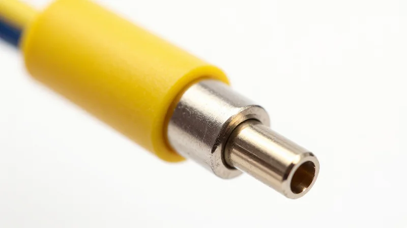
The primary structural advantage of 200G FR4 solutions lies in their ability to operate over standard G.652 single-mode fiber (SMF) using simple LC duplex connectors. While alternative architectures like SR4 or DR4 require multi-fiber push-on (MPO) connectors and parallel ribbon cables, 200G FR4 employs Wavelength Division Multiplexing (WDM) to combine four 50G optical lanes onto a single pair of fibers. This allows data center operators to scale their bandwidth to 200Gbps immediately without the disruptive and costly process of ripping and replacing existing duplex fiber plants.
Comparing Cabling Complexity and Density
When comparing cabling ecosystems, the choice between duplex SMF and parallel fiber (MPO) impacts both immediate capital expenditure and long-term operational efficiency. LC duplex connectors are the industry standard for their reliability, ease of cleaning, and high-density patching capabilities. In contrast, parallel fiber architectures increase the 'blast radius' of a single cable failure and require specialized cleaning tools and testing procedures.
| Feature | 200G FR4 (Duplex SMF) | 200G SR4/DR4 (Parallel) |
|---|---|---|
| Connector Type | LC Duplex | MPO-8 or MPO-12 |
| Fiber Count | 2 Fibers (1 Pair) | 8 or 12 Fibers |
| Max Distance | Up to 2km | 100m (SR4) / 500m (DR4) |
| Cable Management | Low Complexity | High Complexity |
| Infrastructure Cost | Minimal (Legacy Ready) | High (New Install Required) |
Operational Benefits of Single-Mode Infrastructure
Leveraging single-mode fiber (SMF) provides a future-proof path beyond 200G. Unlike multi-mode fiber (MMF), which is often limited by modal dispersion and distance constraints, SMF supports significantly higher reach—up to 2km for FR4—making it ideal for large-scale leaf-spine architectures and campus-wide deployments. By sticking with LC-based SMF, facilities can migrate to 400G and 800G in the future by simply swapping transceivers, rather than undergoing a total overhaul of the physical layer.
Cabling Infrastructure FAQ
- Can 200G FR4 run on existing 100G CWDM4 cabling?
Yes, 200G FR4 is designed to run on the same duplex single-mode fiber used for 100G CWDM4, making it a seamless 'drop-in' upgrade for existing infrastructure. - Why is LC duplex preferred over MPO for maintenance?
LC connectors are easier to inspect and clean using standard tools. MPO connectors are more sensitive to dust and require more complex verification, which increases the likelihood of link errors in high-scale deployments. - Does using 200G FR4 reduce the total number of patch panels needed?
Absolutely. Because FR4 uses only two fibers per link, it requires significantly fewer patch panel ports and less rack space for cable management compared to parallel fiber solutions that consume 8-12 fibers per link.
Application Use Cases: From Edge to Hyperscale

200G FR4 solutions serve as the critical bridge in modern network architecture, offering a 2km reach that makes them the optimal choice for high-density interconnects where 100-meter multi-mode solutions fall short and long-haul 10km optics are cost-prohibitive. By leveraging CWDM4 technology over single-mode fiber, these modules provide the necessary reach for large-scale leaf-to-spine fabrics while maintaining a power profile conducive to high-radix switch deployments.
Hyperscale Data Centers: Scaling the Leaf-to-Spine Tier
In hyperscale environments, the physical footprint often spans several thousand square meters, making the 100m limit of SR4 optics a significant bottleneck for leaf-to-spine connections. 200G FR4 allows for flexible equipment placement across different rows or even different halls within the same facility. This distance flexibility enables a non-blocking architecture that can scale without the constraints of physical proximity.
| Use Case Scenario | Preferred Technology | Primary Advantage |
|---|---|---|
| Intra-Rack (Top of Rack) | DAC / AOC | Lowest cost and power |
| Inter-Rack (Leaf-to-Spine) | 200G FR4 | 2km reach over duplex SMF |
| Campus Connectivity | 200G LR4 | Up to 10km reach |
| AI Training Clusters | 200G FR4 / DR4 | Low latency and high density |
Edge Computing and Regional Hubs
Edge computing sites often inherit existing single-mode fiber (SMF) plants from legacy telecommunications infrastructure. 200G FR4 is uniquely positioned for these environments because it utilizes LC duplex connectors, allowing operators to upgrade from 10G or 40G to 200G without replacing the underlying cabling. This 'plug-and-play' compatibility reduces the time-to-market for 5G backhaul and low-latency edge services.
High-Performance Computing (HPC) and AI Backends
The rise of Generative AI has necessitated massive backend networks to handle East-West traffic between GPU clusters. While some specialized environments use proprietary interconnects, 200G FR4 provides a standardized, interoperable Ethernet path for data ingest and storage networking. Its ability to support dense breakout configurations (e.g., 2x100G) further enhances its utility in AI data pipelines where bandwidth granularity is required.
Common Questions on 200G FR4 Deployment
- Can 200G FR4 be used with legacy OM3/OM4 fiber?
No, 200G FR4 is designed specifically for Single-Mode Fiber (SMF) and utilizes CWDM wavelengths that are not compatible with Multi-Mode Fiber (MMF). - Is 200G FR4 suitable for outdoor enclosures?
While the optics themselves are typically rated for commercial temperature ranges (0-70°C), industrial-grade (I-Temp) versions exist for ruggedized edge deployments in uncontrolled environments. - How does FR4 compare to DR4 for AI workloads?
DR4 uses four parallel fibers (MPO), which is great for short-range breakout, but FR4 is superior for longer spans and reducing cable bulk due to its duplex LC design.
Future-Proofing: Bridging the Path to 800G
The Strategic Role of 200G-per-lane Architecture
200G FR4 is more than a simple capacity upgrade; it represents the fundamental architectural shift required to enable the 800G and 1.6T ecosystems. By adopting 200G-per-lane (200G Lambda) signaling, data centers align their physical layer with the roadmap of next-generation ASICs and high-radix switches. This transition ensures that current investments in single-mode fiber (SMF) and transceiver form factors provide a viable, scalable blueprint for upcoming 800G deployments, effectively bridging the gap between legacy 100G-per-lane designs and future ultra-high-bandwidth requirements.
Technical Synergy Between 200G and 800G Systems
The move to 800G depends heavily on the maturation of 200G-per-lane technology. Using 200G FR4 as a stepping stone allows operators to solve the challenges of PAM4 signal integrity and forward error correction (FEC) at 200G speeds before scaling to the 4x200G or 8x200G configurations found in 800G and 1.6T modules. This approach reduces the risk of thermal runaway and signal degradation that would otherwise occur if jumping directly from 100G-per-lane 400G systems to 800G.
| System Generation | Lane Configuration | Standard Optical Rate | Total Bandwidth |
|---|---|---|---|
| Current 200G FR4 | 1 x 200G (Optical) | 200G-per-lane | 200 Gbps |
| Emerging 800G FR4 | 4 x 200G | 200G-per-lane | 800 Gbps |
| Future 1.6T DR8 | 8 x 200G | 200G-per-lane | 1.6 Tbps |
Future-Proofing FAQ
- Why is 200G-per-lane critical for 800G transition?
It allows 800G transceivers to utilize 4 lanes instead of 8, significantly reducing the complexity of the optical sub-assembly and lowering overall power consumption per bit. - Does 200G FR4 protect existing fiber investments?
Yes, 200G FR4 operates on standard single-mode fiber (SMF) using LC duplex connectors, which are the same infrastructure components required for 800G FR4.4 and FR4.8 standards. - How does 200G FR4 assist with 1.6T scaling?
By perfecting the 200G electrical-to-optical interface today, manufacturers can cluster eight of these lanes into a single OSFP-XD or QSFP-DD800 form factor to achieve 1.6T speeds.
In conclusion, adopting 200G FR4 today provides a low-risk environment to optimize high-speed signal processing and link budgets. It ensures that when 800G hardware becomes the industry standard, the underlying optical technology and fiber plant are already proven and ready for immediate deployment.
Selecting the right 200G solution is not just a hardware choice, but a strategic infrastructure decision that impacts your bottom line and network performance. Ready to optimize your data center? Contact our technical consulting team for a comprehensive fiber audit and 200G implementation roadmap.