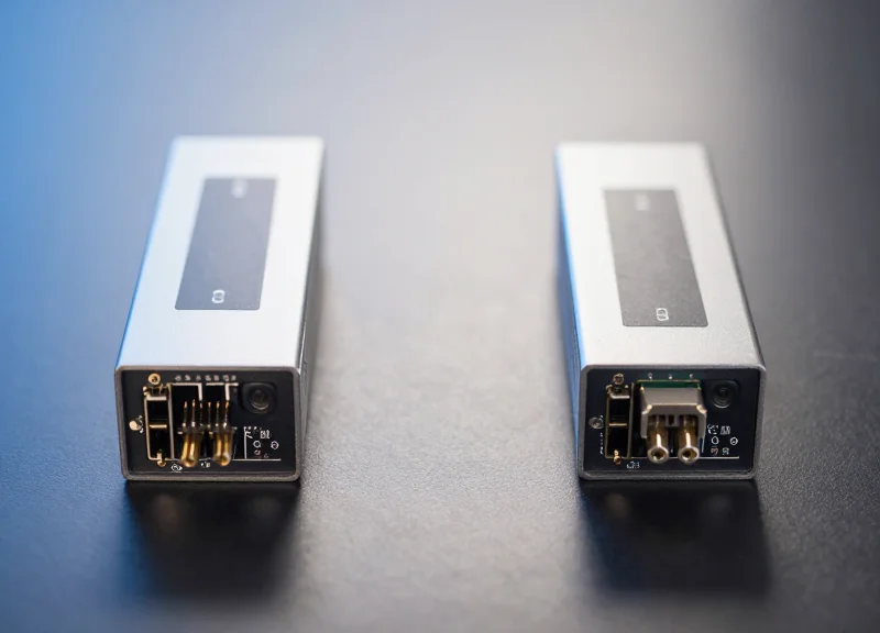
As data centers and enterprise networks transition to 400G, the choice between 400G LR4 and its alternatives has become a high-stakes decision for network architects. While distance is a primary factor, factors like latency, power density, and total cost of ownership (TCO) often dictate the long-term success of a deployment.
The Architecture of 400G LR4: Understanding the 10km Standard
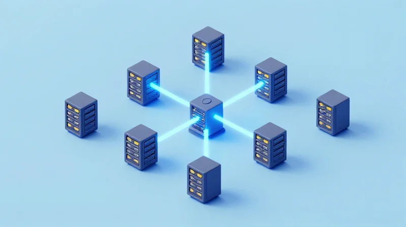
The 400G LR4 architecture is engineered to provide a robust 10km reach over single-mode fiber (SMF), serving as the primary interconnect for high-bandwidth data center campuses and metropolitan networks. Unlike short-reach solutions that rely on parallel multimode fibers, the LR4 standard utilizes a Four-Lane Wavelength Division Multiplexing (WDM) approach. By multiplexing four 100Gbps signals onto a single pair of fibers, it optimizes cable plant density while maintaining the signal integrity required for long-span connectivity.
Modulation and Signal Processing: The Role of PAM4
The transition from 100G to 400G necessitated a shift from traditional NRZ (Non-Return to Zero) signaling to 4-level Pulse Amplitude Modulation (PAM4). In the 400G LR4 architecture, PAM4 allows each optical lane to carry two bits of information per symbol. This effectively doubles the data rate without requiring a proportional increase in bandwidth. To manage the inherent signal degradation and noise sensitivity of PAM4 over 10km, LR4 transceivers incorporate advanced Digital Signal Processing (DSP) and Forward Error Correction (FEC), ensuring the Bit Error Rate (BER) remains within acceptable limits.
Wavelength Management: LWDM vs. CWDM
To achieve 400Gbps, the LR4 standard typically employs the LAN-WDM (LWDM) grid rather than the CWDM grid used in shorter-reach modules like the 400G FR4. LWDM wavelengths are positioned near the zero-dispersion point of single-mode fiber (around 1310nm), which is critical for 10km spans where chromatic dispersion can severely distort PAM4 signals.
| Parameter | 400G LR4 Specification |
|---|---|
| Transmission Distance | Up to 10km |
| Fiber Type | Single-Mode Fiber (G.652) |
| Wavelength Grid | LWDM (1295.56, 1300.05, 1304.58, 1309.14nm) |
| Modulation | 53.125 GBd PAM4 |
| Optical Connector | Duplex LC |
| Max Power Consumption | Typically 10W - 12W |
Architectural Design FAQs
- Why is LWDM preferred over CWDM for 10km?
LWDM uses tighter 800GHz channel spacing located in the narrow O-band window where fiber dispersion is at its lowest, allowing for better signal clarity over longer distances compared to the wider spacing of CWDM. - Does 400G LR4 require FEC?
Yes, the IEEE 802.3bs standard requires KP4 Forward Error Correction (FEC) on the host side to interpret the PAM4 signals correctly and compensate for transmission errors. - What is the typical form factor for LR4?
The most common form factor is the QSFP-DD (Quad Small Form-factor Pluggable Double Density), though OSFP versions are also utilized in specific hardware ecosystems.
Latency Benchmarks: LR4 vs. DR4 and FR4

The Latency Profile of 400G LR4 vs. Alternatives
In modern 400G networking, latency is no longer defined solely by the speed of light through glass; it is increasingly dominated by the computational requirements of Forward Error Correction (FEC) and Digital Signal Processing (DSP). While 400G LR4 is engineered for 10km reach, the signal integrity requirements over that distance necessitate aggressive DSP equalization and error correction, which introduces a measurable delay compared to the 'leaner' processing found in short-reach DR4 and intermediate FR4 optics.
Comparative Latency Benchmarks
| Standard | Reach | Typical DSP Latency | FEC Requirement | Target Use Case |
|---|---|---|---|---|
| 400G DR4 | 500m | ~20-40 ns | KP4 FEC | Intra-DC Leaf-Spine |
| 400G FR4 | 2km | ~50-70 ns | KP4 FEC | Campus/Inter-building |
| 400G LR4 | 10km | ~80-110 ns | KP4 FEC | Metro/Core Aggregation |
The performance gap between these standards stems from the complexity of the DSP's equalization algorithms. In 400G LR4, the DSP must compensate for significant chromatic dispersion and signal attenuation inherent in 10km single-mode fiber runs. This requires more complex taps in the adaptive filter of the DSP, adding nanoseconds to the processing time. For AI training clusters and High-Frequency Trading (HFT) platforms, these cumulative delays across multiple hops can impact synchronization and execution speeds.
FEC Impact: The KP4 Standard
All three standards utilize IEEE 802.3bs mandated KP4 FEC (RS(544,514)) to achieve an acceptable Bit Error Rate (BER) for PAM4 signaling. While the FEC algorithm itself is consistent, the way the DSP handles the FEC framing and interleaving can vary. LR4 modules often prioritize signal robustness over absolute minimum latency to ensure link stability over the full 10km span, whereas DR4 modules are frequently optimized for the lowest possible 'glass-to-glass' delay.
- Does 400G LR4 add significant latency for AI workloads?
For large-scale AI back-end fabrics, LR4 adds approximately 40-60ns of DSP latency per hop compared to DR4. While negligible for a single link, it can become a factor in complex multi-tier Fat-Tree topologies. - Can FEC be disabled on 400G LR4 to reduce latency?
No. Due to the nature of PAM4 modulation and the 10km reach, the Pre-FEC BER is typically too high for the link to operate without KP4 FEC. Disabling it would result in immediate link failure. - How does fiber distance latency compare to DSP latency?
Fiber adds roughly 5µs of latency per kilometer. At 10km, the propagation delay (50µs) far outweighs the DSP latency (0.1µs), but for short links, the DSP delay is the dominant variable.
Power Consumption Dynamics: Thermal Management at 400G
Power Consumption Dynamics: Thermal Management at 400G
The power consumption of 400G LR4 modules is significantly higher than that of short-reach alternatives like DR4 or FR4, primarily due to the necessity of sophisticated laser components and cooling mechanisms required to maintain signal integrity over 10km. While a 400G DR4 module might operate within a 7-9W envelope, an LR4 module frequently pushes toward 12-14W. This delta, though appearing small at the individual component level, compounds rapidly when scaled across high-density switch fabrics, directly impacting the cooling infrastructure and overall operational expenditure (OpEx) of the modern data center.
Comparative Wattage and Component Drivers
The primary driver of the LR4’s higher power profile is the use of Electro-absorption Modulated Lasers (EML) and the integration of Thermo-Electric Coolers (TEC). To achieve the precise wavelength stability needed for 10km transmission over the LAN-WDM grid, the LR4 transceiver must actively regulate its internal temperature. In contrast, DR4 modules often leverage Silicon Photonics or simpler DML designs that lack these power-hungry thermal regulation circuits.
| Module Type | Standard Reach | Typical Power Consumption | Thermal Management Needs |
|---|---|---|---|
| 400G DR4 | 500m | 7.5W - 9.0W | Low - Passive Cooling Support |
| 400G FR4 | 2km | 9.0W - 11.0W | Moderate - Standard Airflow |
| 400G LR4 | 10km | 12.0W - 14.5W | High - Active TEC Required |
The Impact on Rack Density and Cooling Infrastructure
In a 1RU 32-port 400G switch, the transition from FR4 to LR4 optics can increase the heat load by over 100 watts per switch. This thermal overhead forces data center architects to make critical decisions regarding rack density. High-power LR4 modules can lead to 'thermal throttling' where the switch reduces performance to protect circuitry, or necessitates a reduction in port density to ensure adequate airflow. For facilities optimized for 10-15kW per rack, a full deployment of LR4 optics can quickly push a rack beyond its cooling capacity, requiring expensive upgrades to liquid cooling or high-velocity CRAC (Computer Room Air Conditioning) systems.
- Does 400G LR4 require special cooling compared to shorter reach optics?
Yes, due to its internal TEC, the LR4 generates more localized heat. Ensuring unobstructed airflow and maintaining lower ambient temperatures at the intake is more critical for LR4 than for DR4 modules. - How does power consumption affect the total cost of ownership (TCO)?
Higher wattage translates to higher electricity costs for the module itself and higher energy costs for the cooling systems. Over a five-year lifecycle, the OpEx for LR4 can be 30-40% higher than FR4 due to these thermal factors. - Can 400G LR4 modules be used in all 400G switch ports?
While physically compatible, users must check the switch's power budget per port. Some low-power leaf switches may only support high-wattage LR4 modules in specific 'high-power' designated slots.
Total Cost of Ownership (TCO): Beyond the Initial Purchase

Total Cost of Ownership (TCO): Beyond the Initial Purchase
Evaluating the TCO of 400G LR4 requires looking past the unit price and considering the entire lifecycle of the data center network, where fiber utilization and power consumption often outweigh initial Capital Expenditure (CAPEX). While 400G LR4 transceivers command a premium over short-reach alternatives like DR4 or FR4, they offer a decisive advantage in long-span environments by utilizing standard LC duplex single-mode fiber (SMF), which minimizes the need for costly cable overhauls.
CAPEX: Infrastructure and Cabling Savings
The most significant CAPEX offset for LR4 is fiber density. 400G LR4 uses WDM (Wavelength Division Multiplexing) to transmit signals over a single pair of fibers. In contrast, 400G DR4 requires eight fibers (parallel optics) via MPO-12 connectors. For data centers with existing duplex SMF infrastructure, deploying LR4 avoids the massive expense of installing new high-count MPO trunks, which can cost thousands of dollars per rack in labor and materials.
| Metric | 400G LR4 | 400G FR4 | 400G DR4 |
|---|---|---|---|
| Transceiver Cost | Highest | Moderate | Lowest |
| Fiber Count | 2 (Duplex LC) | 2 (Duplex LC) | 8 (MPO-12) |
| Cabling Cost | Lowest (Legacy SMF) | Low | High (MPO Trunks) |
| Typical Reach | 10km | 2km | 500m |
OPEX: Energy Efficiency and Cooling
Operational Expenditure (OPEX) at 400G is largely driven by power consumption and the resulting thermal management requirements. 400G LR4 modules typically draw between 10W and 12W. While this is slightly higher than the 7W to 9W range of DR4 modules, the ability to consolidate links over longer distances can reduce the total number of intermediate switches and regenerators needed, leading to a net reduction in facility-wide power usage and cooling demands.
- Is 400G LR4 worth the extra cost for distances under 2km?
Generally no; 400G FR4 is more cost-effective for 2km spans. LR4's price premium is only justified when the reach exceeds 2km or when fiber availability is so limited that WDM is mandatory. - How does LR4 impact rack density?
Because LR4 uses LC connectors, it allows for high-density patching without the bulk of MPO breakout cables, though the higher heat dissipation per module may require more aggressive airflow management in the rack. - What is the primary long-term saving with LR4?
The primary saving is the avoidance of 'fiber exhaustion.' By using only two fibers per 400G link, operators preserve their existing fiber plant for future expansion without laying new glass.
Signal Integrity and Reliability: Why LR4 Dominates Campus Backbones
Signal Integrity and Reliability: Why LR4 Dominates Campus Backbones
400G LR4 dominates campus backbones because its 10km-rated optical link budget provides a critical performance buffer that shorter-reach standards like FR4 or DR4 cannot match. In real-world campus environments, signal degradation is not merely a function of distance; it is driven by the cumulative loss from multiple patch panels, cross-connects, and aging fiber splices. LR4’s ability to maintain high Optical Signal-to-Noise Ratio (OSNR) in the face of these 'brownfield' infrastructure challenges ensures consistent bit-error rate (BER) performance and reduces the reliance on aggressive Forward Error Correction (FEC), which can otherwise introduce latency.
The Link Budget Advantage: Margin for Error
While 400G FR4 is designed for 2km reaches with a link budget often hovering around 4dB, 400G LR4 provides approximately 6.3dB to 6.6dB. This extra 2.5dB margin is decisive in campus backbones where the fiber path is rarely a straight line. Every intermediate distribution frame (IDF) or main distribution frame (MDF) transition adds insertion loss. For a campus network with four or five patch points, the 4dB budget of an FR4 module is quickly exhausted, leading to intermittent link flapping or total signal failure. LR4’s higher launch power and receiver sensitivity allow it to absorb these losses comfortably.
| Specification | 400G LR4 (10km) | 400G FR4 (2km) | 400G DR4 (500m) |
|---|---|---|---|
| Typical Link Budget | ~6.3 dB | ~4.0 dB | ~3.0 dB |
| Max Fiber Loss Allowance | ~0.6 dB/km | ~0.5 dB/km | ~0.5 dB/km |
| Tolerance for Splices/Patches | High | Moderate | Low |
| OSNR Sensitivity | High | Moderate | Low |
Mitigating PAM4 Dispersion and Noise
The transition from NRZ to PAM4 signaling at 400G makes signal integrity more sensitive to noise and chromatic dispersion. LR4 modules utilize four wavelengths on the CWDM grid (1271 to 1331nm) with sophisticated TOSA/ROSA components designed to mitigate the effects of dispersion over longer distances. In high-interference environments—such as those where fiber runs parallel to high-voltage power lines in campus utility tunnels—the robust OSNR of LR4 ensures that the PAM4 'eyes' remain open enough for the DSP to decode the signal without exceeding the FEC limit.
- Does LR4 require special fiber for campus use?
No, it operates on standard G.652 single-mode fiber, but its higher link budget makes it more forgiving of older fiber plant conditions compared to FR4. - Why is OSNR more critical at 400G?
Because PAM4 signaling uses four voltage levels instead of two, the vertical eye opening is significantly smaller, making the signal much more susceptible to noise. - Can LR4 be used for shorter distances?
Yes, though an attenuator may be required if the link is shorter than 2km to prevent receiver saturation, given its high launch power.
Choosing the Right Standard: 400G LR4 vs. 400G FR4
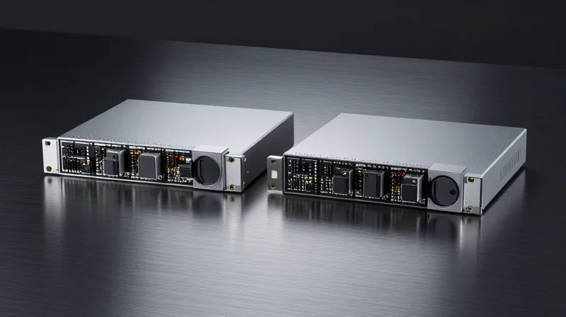
Selecting between 400G LR4 and 400G FR4 is primarily a function of the physical distance required for the link and the permissible power budget. While both standards utilize CWDM4 or LAN-WDM technologies to transmit 400G over single-mode fiber (SMF), FR4 is optimized for distances up to 2km, offering significant cost and power savings, whereas LR4 is the indispensable choice for links between 2km and 10km where signal integrity over longer spans is paramount.
Technical Specification Comparison
| Feature | 400G FR4 | 400G LR4 |
|---|---|---|
| Max Distance | 2 km | 10 km |
| Fiber Type | Single-mode (OS2) | Single-mode (OS2) |
| Wavelengths | CWDM (1271, 1291, 1311, 1331nm) | LAN-WDM (1295, 1300, 1304, 1309nm) |
| Power Consumption | Lower (~7-10W) | Higher (~12-14W) |
| Primary Use Case | Intra-campus / DC Interconnect | Campus Backbone / Metropolitan |
The Economic Shift: When to Choose LR4
The performance-to-cost ratio shifts dramatically at the 2km mark. For data center operators, 400G FR4 is the more economical solution for the majority of internal cabling due to its lower manufacturing complexity and reduced power cooling requirements. However, once the link distance exceeds the 2km threshold, signal attenuation and dispersion in FR4 optics become prohibitive. At this point, the investment in 400G LR4 becomes necessary. LR4 utilizes more precise LAN-WDM laser spacing and higher-quality optical components to maintain an acceptable Optical Signal-to-Noise Ratio (OSNR) over the full 10km range.
Infrastructure Longevity and Future-Proofing
Enterprises must also consider the 'hidden' costs of fiber plant upgrades. If a facility currently operates at distances approaching 1.8km, deploying LR4 may be a safer long-term strategy. While more expensive upfront, LR4 provides a larger link budget buffer, which can accommodate higher patch panel loss or future additions to the optical path without requiring a complete move to 400G-ER4 or coherent optics.
Implementation FAQ
- Can 400G LR4 and 400G FR4 interoperate?
Generally, no. They use different wavelength grids (LAN-WDM vs. CWDM), meaning the lasers and filters are not aligned. They are designed as discrete standards for specific distance tiers. - Is LR4 always better if budget allows?
Not necessarily. LR4 modules typically consume more power, which can lead to higher OPEX and thermal management challenges in high-density racks. FR4 is the superior choice for high-efficiency, short-reach applications. - How does 400G DR4 fit into this comparison?
DR4 is intended for even shorter reaches (500m) and uses parallel fiber (MPO) rather than multiplexed fiber (LC). If you have a duplex LC fiber plant, FR4 or LR4 are your primary options.
Deployment Scenarios: When LR4 is the Only Viable Solution
While 400G DR4 and FR4 solutions offer cost advantages for short-range and mid-range applications, 400G LR4 is the only viable solution when geographical distance, fiber path complexity, and signal integrity requirements intersect at the 10km threshold. In environments like Metropolitan Area Networks (MAN) and expansive campus backbones, the necessity for a 6.3dB link budget and 1310nm wavelength stability renders shorter-reach alternatives technically insufficient.
Metropolitan Area Network (MAN) and Data Center Interconnects
In urban environments, Data Center Interconnect (DCI) links between facilities often span between 5km and 10km. Although a map might show two sites separated by only 2km, the actual fiber route—dictated by existing conduit paths, utility rights-of-way, and subway tunnels—frequently doubles or triples that distance. For these routes, the 2km limit of 400G FR4 is a hard physical barrier. 400G LR4 provides the necessary reach to bridge these city-scale gaps without requiring mid-span amplification or signal regeneration, which would otherwise introduce significant latency and increase capital expenditure.
| Scenario | Average Fiber Length | Primary Constraint | Recommended 400G Standard |
|---|---|---|---|
| Intra-Building Spine | 100m - 500m | Cost and Power Density | SR8 / DR4 |
| Campus Inter-Building | 500m - 2km | Fiber Type/Availability | FR4 |
| Metro DCI / Regional Hub | 2km - 10km | Physical Distance Reach | LR4 |
| High-Loss Complex Routes | 3km - 8km | Optical Link Budget | LR4 |
Complex Enterprise Backbones and High-Loss Paths
Large enterprise backbones, particularly in legacy industrial environments or sprawling university campuses, often feature fiber runs with multiple patch panels, splices, and older single-mode fiber (SMF) types that introduce high attenuation. In these scenarios, the optical power budget becomes the deciding factor rather than just raw distance. While an FR4 module might technically reach 2km on pristine fiber, it lacks the 'cushion' to handle a 4dB or 5dB loss across a complex 4km path. LR4's higher transmit power and superior receiver sensitivity ensure reliable performance where other modules would suffer from unrecoverable bit error rates (BER).
The 1310nm Advantage in High-Interference Zones
Operating in the 1310nm window, 400G LR4 benefits from near-zero chromatic dispersion on standard G.652 fiber. This is critical for 400G throughput where PAM4 modulation is highly sensitive to signal distortion. In scenarios involving co-location with high-voltage equipment or high-vibration industrial sectors, the stability provided by the LR4 wavelength grid ensures a stable link where shorter-reach, less robust optics might experience frequent link flaps.
- When is 400G LR4 considered the only option?
LR4 is mandatory when the total end-to-end fiber distance exceeds 2km or when the total link loss exceeds the 4dB threshold typically supported by FR4 optics. - Can LR4 be used for short distances to simplify inventory?
While possible, LR4 is usually overkill for distances under 2km. However, some enterprises standardize on LR4 for all single-mode links to simplify sparing and maintenance across a diverse MAN footprint. - What happens if I use FR4 on a 5km link?
The signal will likely be too weak for the receiver to decode, resulting in a failed link or high error rates that the Forward Error Correction (FEC) cannot manage.
Future-Proofing Your Network: Scaling from 400G to 800G
The Strategic Bridge: 400G LR4 as a Foundation for 800G
Investing in 400G LR4 is not merely a solution for today’s long-distance requirements; it is a strategic investment in infrastructure that simplifies the eventual migration to 800G and 1.6T standards. Because 400G LR4 utilizes standard G.652 singlemode fiber (SMF), the physical layer remains consistent even as active equipment is upgraded. The primary shift occurs in the signaling density and the serialization/deserialization (SerDes) rates. Organizations that deploy LR4 today are effectively establishing a high-performance baseline that can support dual-carrier 800G configurations or breakout strategies as data center and metropolitan demands evolve.
SerDes Evolution: 56G to 112G and Beyond
The transition from 400G to 800G is largely driven by the move from 56G PAM4 SerDes to 112G PAM4 SerDes. Most current 400G LR4 modules operate on 8 lanes of 50G (or 4 lanes of 100G in newer iterations). To future-proof, network architects should prioritize 400G hardware that is compatible with newer 112G-based ASICs. This ensures that when the switch fabric is upgraded to 800G, the existing 400G LR4 links can be integrated into the new high-density ports—often via 2x400G breakout cables—without requiring a complete overhaul of the optical distribution frames.
| Feature | 400G LR4 (Current) | 800G (Intermediate) | 800G/1.6T (Native) |
|---|---|---|---|
| Mainstream SerDes | 56G PAM4 | 112G PAM4 | 224G PAM4 (Target) |
| Optical Lanes | 4 x 100G (CWDM) | 8 x 100G or 2 x 400G | 8 x 200G |
| Typical Reach | 10km | 2km - 10km | TBD (LR Variants) |
| Form Factor | QSFP-DD / OSFP | QSFP-DD800 / OSFP | OSFP-XD |
Common Scaling and Migration Questions
- Can current 400G LR4 modules be used in 800G switch ports?
Yes, most 800G QSFP-DD800 and OSFP ports are backward compatible with 400G modules, allowing you to maintain your LR4 links while upgrading the core switch fabric. - Does 800G require new fiber cabling?
No, for long-distance applications, 800G will continue to leverage standard singlemode fiber (SMF). Your investment in LR4 fiber infrastructure remains fully valid for the next two generations of networking. - What is the role of 400G LR4 in a 1.6T roadmap?
In 1.6T environments, 400G LR4 modules will likely serve as 'edge' or 'tributary' links, aggregating lower-speed traffic into massive core pipes via high-density breakout panels.
Ultimately, the choice of 400G LR4 today should be viewed through the lens of power efficiency and port density. Opting for modules with lower power consumption and better thermal management now will pay dividends when those modules are densely packed into next-generation 800G-capable chassis.
Selecting the right 400G standard requires a delicate balance of technical performance and fiscal responsibility. While 400G LR4 offers unmatched 10km performance, understanding its TCO profile is key to a sustainable upgrade. Contact our engineering team today for a customized network assessment to optimize your 400G deployment.