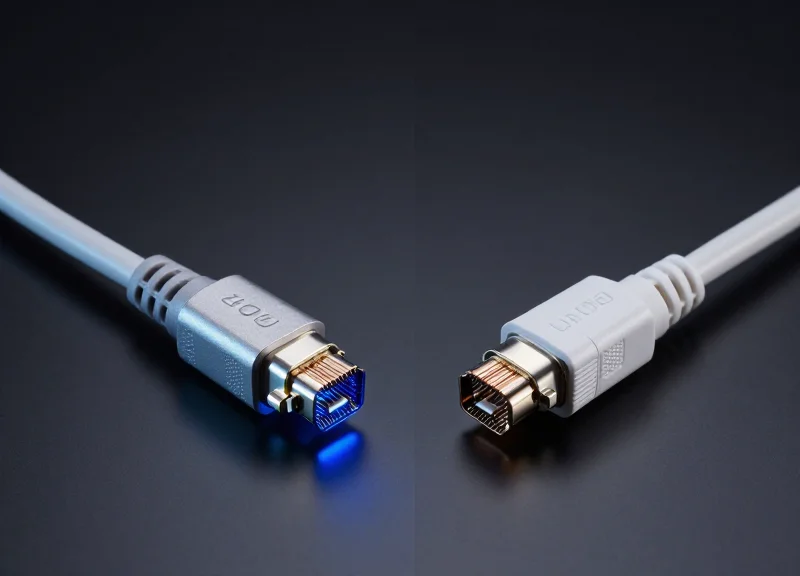
As data centers transition to 400G and beyond, the choice of interconnect technology has shifted from a simple cabling decision to a strategic architectural requirement. With the pressure to balance escalating power costs against the need for ultra-low latency, understanding the nuances between Direct Attach Copper (DAC), Active Optical Cables (AOC), and emerging alternatives like AEC is critical for maintaining a competitive edge in high-performance computing and AI workloads.
The Evolution of 400G Interconnects

The Evolution of 400G Interconnects
The transition to 400G Ethernet marks a paradigm shift in high-speed networking, necessitated by the move from traditional Non-Return-to-Zero (NRZ) signaling to 4-level Pulse Amplitude Modulation (PAM4). While previous generations focused on increasing clock speeds to achieve higher throughput, 400G overcomes the physical limitations of signal degradation by increasing the density of data transmitted per symbol. This evolution fundamentally changes how Direct Attach Cables (DAC), Active Optical Cables (AOC), and optical transceivers are engineered to maintain signal integrity across the data center fabric.
The Shift from NRZ to PAM4 Modulation
At 100G speeds, NRZ signaling was the industry standard, utilizing two voltage levels to represent binary data. However, as bandwidth demands scaled toward 400G, the electrical requirements for NRZ led to excessive insertion loss and electromagnetic interference. PAM4 addresses these challenges by utilizing four distinct signal levels, allowing each symbol to carry two bits of information. While this effectively doubles the data rate at the same baud rate, it also introduces a significantly tighter Signal-to-Noise Ratio (SNR) margin, making the interconnects more sensitive to noise and requiring the integration of Digital Signal Processors (DSP).
| Parameter | NRZ (100G Era) | PAM4 (400G Era) |
|---|---|---|
| Bits per Symbol | 1 bit | 2 bits |
| Signal Levels | 2 (High/Low) | 4 (00, 01, 10, 11) |
| Signal-to-Noise Ratio | High (Better) | Low (More Challenging) |
| Error Correction | Optional (FEC) | Mandatory (FEC Required) |
| Primary Interconnect Use | Standard DAC/AOC | DSP-based DAC/AOC/Optical |
Physical Layer Challenges and Solutions
The adoption of 400G has redefined the physical limits of copper and optical media. In 400G environments, passive DACs are typically limited to lengths of less than 3 meters due to the high frequency of PAM4 signals. To bridge longer distances, the industry has turned to Active Copper Cables (ACC) and Active Optical Cables (AOC). These alternatives incorporate active components to boost or regenerate signals, compensating for the inherent losses in the transmission medium and ensuring that the complex four-level signals reach their destination with an acceptable Bit Error Rate (BER).
- Why is PAM4 necessary for 400G?
PAM4 allows for doubling the data throughput without doubling the required bandwidth (baud rate), which helps circumvent the physical frequency limits of copper and fiber optics. - Does 400G require Forward Error Correction (FEC)?
Yes, due to the reduced signal margins in PAM4, FEC is essential for detecting and correcting bit errors, ensuring reliable data transmission across the physical link. - How does 400G affect cable length?
High-frequency PAM4 signals degrade more quickly than NRZ, leading to shorter reach for passive copper cables and a greater reliance on active or optical solutions for distances exceeding 2.5 meters.
400G DAC: The Zero-Power Copper Standard
400G DAC: The Zero-Power Copper Standard
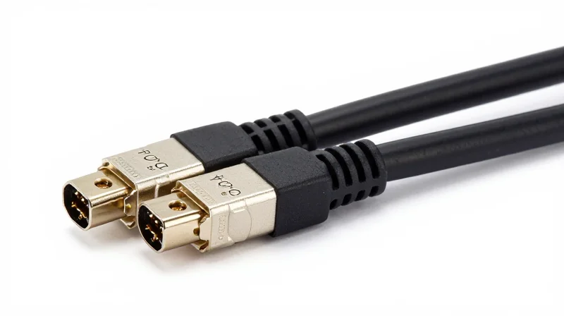
In the hierarchy of 400G interconnects, Direct Attach Copper (DAC) represents the most cost-effective and energy-efficient solution for top-of-rack (ToR) switching. By utilizing passive copper twinaxial cables, 400G DACs transmit signals without active components, resulting in virtually no power draw and the lowest possible latency profile for intra-rack connections. As data centers face increasing thermal pressure, the 'zero-power' nature of DACs makes them an indispensable tool for high-density deployments where cooling capacity is at a premium.
The Engineering Trade-off: Reach vs. Signal Integrity
The transition to 400G has significantly altered the physical reach of copper. Unlike previous generations where passive copper could reliably span up to 7 meters, the shift to 56G PAM4 modulation introduces extreme signal attenuation and electromagnetic interference (EMI) challenges. For 400G DACs, the effective range is typically capped at 2.5 to 3 meters. Beyond this distance, the bit error rate (BER) increases to a point where signal recovery becomes impossible without active equalization or optical conversion.
| Feature | Passive 400G DAC Specification | Operational Impact |
|---|---|---|
| Power Consumption | Near 0W | Negligible heat generation; lowers TCO. |
| Maximum Reach | 0.5m - 2.5m (typically) | Restricted to intra-rack or adjacent rack use. |
| Latency | Sub-nanosecond | Lowest latency available; ideal for HPC and AI. |
| Cable Gauge | 26AWG to 30AWG | Thicker gauges offer more reach but less flexibility. |
Thermal Management and Cost Efficiency
The primary advantage of the 400G DAC is its impact on the data center's thermal envelope. Since the cable does not contain lasers or signal-processing chips, it does not contribute to the heat load of the switch port. This allows network engineers to fully populate 400G switches without exceeding the thermal limits of the chassis. From a CAPEX perspective, DACs are often 1/10th the cost of optical transceivers, making them the default choice for the 'last meter' of the network.
400G DAC Implementation FAQ
- Why is the 400G DAC distance shorter than 100G DAC?
Higher frequencies required for PAM4 modulation suffer from higher insertion loss. To maintain signal integrity without active amplification, the physical length of the copper must be reduced. - Are 400G DACs compatible with all QSFP-DD and OSFP ports?
While physically compatible, compatibility depends on the host switch's firmware and its ability to handle the specific EEPROM signature of the cable. Always verify vendor-specific compatibility matrices. - When should I choose DAC over AOC for 400G?
Choose DAC for any connection under 2.5 meters where cost and power efficiency are priorities. AOCs should only be considered when cable management (flexibility) or distances beyond 3 meters are required.
400G AOC: Bridging Distance with Optics
400G AOC: Bridging Distance with Optics
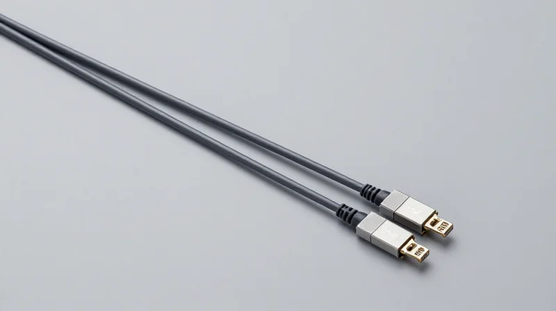
400G Active Optical Cables (AOC) serve as the vital link where passive copper reaches its physical limit, providing a high-bandwidth, low-bit-error-rate solution for distances up to 100 meters. Unlike Direct Attach Copper (DAC), which suffers from massive signal attenuation at 400G speeds beyond a few meters, AOCs integrate optical transceivers directly into the cable ends, converting electrical signals to light. This transition to optics allows data centers to maintain the plug-and-play simplicity of a cable assembly while achieving the reach necessary for Top-of-Rack (ToR) to End-of-Row (EoR) architectures.
Lightweight Architecture and Cable Management
One of the most significant advantages of 400G AOCs is their physical profile. Because they utilize thin optical fibers rather than heavy-gauge copper wiring, they are substantially lighter and thinner. In high-density environments where hundreds of cables converge, AOCs reduce the physical bulk in cable trays and behind server racks. This improved 'bend radius' and reduced diameter not only simplify installation but also enhance airflow, which is critical for cooling 400G switches that generate significant heat.
EMI Immunity in High-Density Environments
As data centers pack more hardware into smaller footprints, Electromagnetic Interference (EMI) becomes a major hurdle for copper interconnects. 400G AOCs are inherently immune to EMI because the transmission medium is glass fiber rather than conductive metal. This makes them the preferred choice for mission-critical deployments where signal integrity cannot be compromised by the electrical noise of neighboring high-power equipment or power supplies.
| Feature | 400G DAC (Copper) | 400G AOC (Optical) |
|---|---|---|
| Maximum Reach | Up to 2.5m - 3m | Up to 100m |
| Weight/Bulk | Heavy, Thick (AWG26-30) | Light, Thin (Optical Fiber) |
| EMI Resistance | Susceptible | Inherently Immune |
| Power Consumption | Near Zero | ~2W - 10W per end |
Strategic Deployment Use Cases
- End-of-Row (EoR) Connectivity
Linking server racks to a centralized switch located at the end of the row where distances exceed 3 meters. - Spine-Leaf Architecture
Connecting leaf switches to spine switches within the same data hall to ensure high-speed PAM4 throughput over moderate distances. - High-Performance Computing (HPC)
Utilized in clusters where low latency and high signal integrity are required across a distributed compute fabric.
Common Questions on 400G AOC
- Are 400G AOCs more expensive than DACs?
Yes, AOCs involve active optical components and lasers, making their unit cost significantly higher than passive copper, though they are often cheaper than using two discrete transceivers and a separate fiber patch lead. - Can I use AOCs for inter-building connections?
Generally no. 400G AOCs are designed for intra-data center use (within the same room) with a typical max reach of 100m. For inter-building links, discrete transceivers with single-mode fiber are required. - Do 400G AOCs support breakout configurations?
Yes, 400G AOCs are commonly available in breakout formats, such as 400G QSFP-DD to 4x 100G QSFP56, to connect high-speed uplinks to multiple lower-speed nodes.
The Rise of AEC and ACC: Necessary Alternatives?
As 400G networks transition to PAM4 signaling, the physical limitations of passive Direct Attach Copper (DAC) have become a bottleneck, often restricted to less than 2.5 meters. Active Copper Cables (ACC) and Active Electrical Cables (AEC) have emerged as essential alternatives, providing the signal conditioning necessary to extend the life of copper interconnects in the data center while avoiding the high cost and power overhead of fully optical solutions.
Understanding ACC vs. AEC Technology
While both are 'active' copper solutions, they utilize different methods to overcome signal attenuation. Active Copper Cables (ACC) employ linear equalization at the receive end to amplify the signal, effectively extending the reach to approximately 4 or 5 meters. They are essentially 'Redriver' solutions that boost the signal without performing full clock and data recovery (CDR).
In contrast, Active Electrical Cables (AEC) are more sophisticated. They incorporate Retimers or Distributed Signal Processing (DSP) chips within the connector shells. This allows the AEC to perform clock recovery and signal regeneration, stripping away jitter and noise before re-transmitting the signal. This robust processing enables AECs to reach up to 7 meters with much thinner gauges than traditional DACs, significantly improving airflow and cable management in high-density racks.
| Feature | Passive DAC | Active Copper (ACC) | Active Electrical (AEC) | Active Optical (AOC) |
|---|---|---|---|---|
| Max Reach (400G) | ~2m - 2.5m | ~4m - 5m | Up to 7m | Up to 100m+ |
| Signal Processing | None (Passive) | Linear Equalization | Retiming / DSP | Optical Conversion |
| Power Consumption | Zero | ~0.1W - 0.5W | ~3W - 5W | ~7W - 10W |
| Cable Diameter | Thick (26-30 AWG) | Medium | Thin (32-34 AWG) | Thinnest (Fiber) |
The Strategic Advantages of AEC and ACC
- Why are AECs preferred over DACs for 400G Top-of-Rack (ToR) to Server links?
AECs use significantly thinner cabling than DACs. At 400G, a passive DAC requires heavy-gauge wire to maintain signal integrity, which blocks airflow and makes routing difficult. AECs solve this through active retiming, allowing for thinner 32AWG wire that improves thermal management. - Does ACC provide enough performance for 400G?
ACC is an excellent cost-effective middle ground. It offers better reach than DAC without the power consumption of AEC or AOC. However, it does not clean the signal like an AEC, meaning it is more sensitive to host-side jitter. - Can AEC facilitate breakout configurations?
Yes, AECs are highly effective for gear-boxing and breakout applications (e.g., 400G to 4x100G) because the internal DSP can handle the transition between different signaling rates more reliably than passive components.
Latency Benchmarking: DAC vs. AOC vs. AEC

Latency Benchmarking: DAC vs. AOC vs. AEC
In the landscape of 400G networking, latency is the primary differentiator between cable types, with Passive Direct Attach Copper (DAC) providing the lowest possible delay of any interconnect solution. Because Passive DACs rely on direct electrical conduction without active components or signal conversion, they introduce near-zero processing latency, limited only by the physical speed of electrons through copper. In contrast, Active Electrical Cables (AEC) and Active Optical Cables (AOC) introduce 'processing overhead' due to the integrated circuits required to re-time, amplify, or convert signals between electrical and optical domains.
| Interconnect Type | Typical Latency (Total) | Primary Latency Source |
|---|---|---|
| 400G Passive DAC | < 0.1 ns per meter | Physical propagation delay only |
| 400G Active Electrical (AEC) | 100 ns to 150 ns | Re-timer and CDR processing |
| 400G Active Optical (AOC) | 100 ns to 300 ns | E-to-O conversion and DSP overhead |
The Impact of Signal Conditioning and Retiming
The shift to 400G introduced PAM4 (Pulse Amplitude Modulation 4-level) signaling, which is significantly more complex and sensitive to noise than previous generations. To combat signal degradation over distance, AECs utilize Re-timers to perform Clock and Data Recovery (CDR), which essentially 'rebuilds' the signal at the midpoint. This process adds a fixed latency penalty, typically around 100 nanoseconds. AOCs face a similar challenge but add the layer of Electrical-to-Optical (E-to-O) conversion. In many 400G AOCs, a Digital Signal Processor (DSP) is used to manage bit error rates, which can push total interconnect latency toward the 300ns mark depending on the specific chip architecture.
Why Nanoseconds Matter in AI and HFT
For High-Frequency Trading (HFT) environments, a 200ns difference is an eternity; it can be the difference between a filled order and a missed price point. Consequently, DACs are the non-negotiable standard for top-of-rack HFT connections. In AI and Machine Learning clusters, the concern is 'tail latency.' During massive parallel computations, such as All-Reduce operations across thousands of GPUs, the entire cluster must wait for the slowest data packet to arrive. If a network path uses high-latency AOCs instead of low-latency DACs or AECs, the resulting 'jitter' can significantly degrade the efficiency of GPU utilization and prolong model training times.
- Does cable length affect latency?
Yes, for all cable types, there is a base propagation delay of approximately 5 nanoseconds per meter. However, for DACs, this is the only delay, whereas AECs and AOCs add fixed processing delay regardless of length. - Is the latency in AOCs deterministic?
Generally, yes. However, if the internal DSP or the switch port's Forward Error Correction (FEC) has to work harder to resolve errors on an optical link, it can introduce slight variations in packet delivery timing. - When should I prioritize AEC over DAC despite the latency?
AEC is the preferred choice when you need to span distances between 3 and 7 meters where a Passive DAC would fail due to signal loss, but you still require a thinner, more flexible cable than a bulky copper DAC.
Thermal Management and Power Consumption
The Power-Thermal Equation in 400G Interconnects
In 400G ecosystems, power consumption is the pivot point where hardware savings meet operational reality; while passive DACs represent a near-zero power solution for short reaches, the transition to AECs and AOCs introduces a thermal tax of up to 12W per port that necessitates sophisticated cooling strategies and increases long-term electricity costs. At these speeds, the electrical-to-optical conversion and signal retiming processes generate significant localized heat, making thermal management a primary constraint for rack density and port availability.
Wattage Breakdown by Interconnect Type
| Interconnect Type | Typical Power Draw (Per End) | Cooling Requirement | Primary Heat Source |
|---|---|---|---|
| 400G Passive DAC | < 0.1 Watts | Minimal (Ambient) | None |
| 400G ACC (Active Copper) | 1.0 - 2.0 Watts | Low | Linear Redriver |
| 400G AEC (Active Electrical) | 3.0 - 5.0 Watts | Moderate | Retiming DSP |
| 400G AOC (Active Optical) | 8.0 - 12.0 Watts | High | VCSEL/EEL + DSP |
The Cascading Impact on Data Center OPEX
The true cost of power-hungry interconnects like AOCs extends beyond the electricity bill for the cable itself. For every watt consumed by a 400G module, data centers often incur an additional 0.6 to 1.0 watt of power consumption from cooling infrastructure (CRAC/CRAH systems). In a fully populated 32-port 400G switch, opting for AECs over DACs adds roughly 160W of heat per switch, while opting for AOCs can add nearly 400W. Over a three-year lifecycle, this cumulative energy requirement can shift the Total Cost of Ownership (TCO) in favor of passive or lower-power active copper solutions where distance allows.
Frequently Asked Questions: Thermal & Power
- How does heat affect the lifespan of 400G modules?
Operating active modules at the upper limit of their thermal rating (typically 70°C for commercial grade) accelerates the degradation of internal components, particularly the laser diodes in AOCs, leading to higher failure rates and more frequent maintenance cycles. - Why is AEC power consumption higher than ACC?
AECs utilize complex Clock and Data Recovery (CDR) or DSP chips to re-time the signal and eliminate jitter, whereas ACCs use simpler linear redrivers that only boost signal amplitude without full digital reconstruction. - Can high-density switches support 400G AOCs on every port?
While most modern 400G switches are designed for these loads, utilizing high-power AOCs on every port may require high-static pressure fans and specialized airflow ducting to prevent thermal throttling of the switch ASIC.
Total Cost of Ownership (TCO) Analysis
Unpacking the Total Cost of Ownership for 400G Interconnects
A comprehensive TCO analysis for 400G infrastructure goes beyond the purchase price of a cable; it encompasses energy consumption, thermal management, rack density, and the long-term reliability of the link. While Direct Attach Copper (DAC) remains the undisputed leader in low upfront Capital Expenditure (CAPEX), Active Optical Cables (AOC) and transceiver-based solutions often yield lower Operational Expenditure (OPEX) in large-scale deployments where heat dissipation and cable management directly impact the bottom line. Over a 3-to-5-year hardware lifecycle, the 'cheapest' cable on day one can become the most expensive if it forces higher cooling costs or restricts airflow in high-density AI clusters.
The Financial Breakdown: CAPEX vs. OPEX
CAPEX is dominated by the acquisition cost of the hardware. At 400G, a passive DAC typically costs a fraction of an AOC, which in turn is significantly more affordable than a pair of 400G transceivers and the necessary fiber patch cords. However, the OPEX calculation shifts when considering power-per-gigabit. Passive DACs consume no power themselves, but their physical bulk can obstruct airflow, requiring switch fans to work harder. Conversely, while AOCs and transceivers have an internal power draw, their thin profiles optimize rack cooling, potentially reducing overall facility energy bills.
| Cost Factor | Passive DAC | Active Optical Cable (AOC) | Transceivers + Fiber |
|---|---|---|---|
| Upfront Price (CAPEX) | Lowest | Moderate | Highest |
| Power Consumption | 0W | Approx. 2W - 4W per end | Up to 12W - 14W per link |
| Cable Bulk/Airflow | High (Obstruction risk) | Low (Thin/Flexible) | Low (Best for density) |
| Link Testing/Labor | Plug-and-play | Plug-and-play | High (Cleaning/Testing) |
Hidden Variables in TCO Calculations
Beyond power and price, reliability and maintenance labor significantly influence TCO. DACs are passive and thus have higher Mean Time Between Failures (MTBF) compared to active electronics. However, in environments with high electromagnetic interference (EMI), AOCs provide superior signal integrity, reducing the 'cost' of data retransmissions and latency spikes. Furthermore, the flexibility of AOCs reduces the mechanical stress on switch ports, potentially avoiding costly hardware repairs over time.
- When does DAC lose its cost advantage?
DAC loses its advantage beyond 3 meters, where the weight and bulk of the copper interfere with rack density and cooling, or when the cost of Active Electrical Cables (AEC) needed for longer reaches approaches the price of AOCs. - How much does power consumption impact TCO?
In a data center, every watt of power used by a transceiver requires roughly 0.5 to 1.0 watts of cooling power. Saving 5W per port across a 32-port switch can save hundreds of dollars in electricity over the device's lifespan. - Is the 'Cleaning Cost' for optics significant?
Yes, for transceiver-plus-fiber solutions, the labor for inspection and cleaning of fiber end-faces is a significant OPEX hit that AOCs and DACs avoid entirely due to their factory-sealed connectors.
Use-Case Optimization: Which One to Choose?
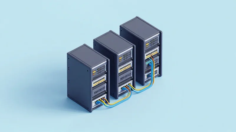
The decision to deploy 400G DAC, AOC, or discrete optical alternatives is primarily dictated by the physical distance of the link and the thermal constraints of the network equipment. For short-reach Top-of-Rack (ToR) connections under 2.5 meters, Direct Attach Copper (DAC) remains the industry standard due to its zero power consumption and cost-effectiveness. However, as link lengths extend toward the 3-meter to 100-meter range—typical of Leaf-to-Spine or Row-to-Row transitions—Active Optical Cables (AOC) and optical transceivers become essential to maintain signal integrity and manage cable weight.
Decision Matrix: Interconnect Selection by Reach
| Topology Link | Distance Range | Recommended Interconnect | Primary Benefit |
|---|---|---|---|
| Intra-Rack (Server to ToR) | 0.5m - 2.5m | 400G DAC | Lowest latency and $0 power cost. |
| Inter-Rack (Mid-Row) | 3m - 30m | 400G AOC | Thin, flexible cabling for airflow. |
| Spine-Leaf / Campus link | 30m - 100m | 400G SR4/DR4 Transceiver | High scalability and structured cabling support. |
| AI / HPC Compute Fabric | < 2.0m | 400G DAC | Maximum nanosecond-level latency reduction. |
Optimizing for AI Clusters and High-Density Environments
In AI training clusters and High-Performance Computing (HPC) environments, the 'interconnect tax'—both in terms of power draw and latency—is a critical metric. Using 400G DACs for GPU-to-GPU communication within a single rack avoids the latency penalty of Optical-Electrical-Optical (OEO) conversion. Conversely, in high-density cloud environments where airflow is restricted, the bulk of 400G DACs (often using thick 26AWG copper) can create thermal bottlenecks. In these specific cases, AOCs are preferred even for short runs because their thinner profile significantly improves rack-front airflow and cooling efficiency.
Optimization FAQ: Navigating Implementation Hurdles
- At what exact distance should I stop using 400G DAC?
Technically, 400G DACs can reach 3 meters, but signal stability and cable bulk become problematic beyond 2.5 meters. Most architects transition to AOCs for anything exceeding 2 meters to ensure consistent PAM4 signal quality. - Is there a cost-benefit to using AOCs over discrete transceivers for 50m runs?
For fixed links under 30 meters, AOCs are typically 20% cheaper than a pair of SR4 transceivers plus an MPO cable. However, for links approaching 100 meters, discrete transceivers are more optimized because they allow the use of structured fiber cabling that can be reused across hardware generations. - How does the 'power budget per port' influence the choice?
A 400G DAC consumes nearly 0 Watts, whereas an AOC or transceiver consumes 8W to 12W per end. In a 32-port switch, using AOCs can add nearly 400W of heat load per switch, which may exceed the cooling capacity of standard enterprise racks.
Installation and Reliability Best Practices
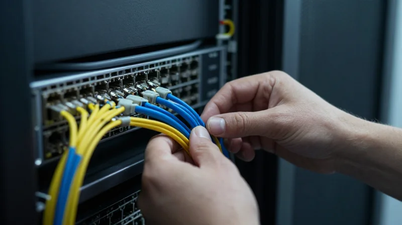
Ensuring Long-Term Stability in 400G Interconnects
Successful 400G deployments require more than just matching transceivers to ports; they necessitate a rigorous approach to physical layer management where mechanical durability meets thermal efficiency. Because 400G DACs are significantly heavier and stiffer than their predecessors, and AOCs rely on sensitive glass fibers, improper handling during installation is a leading cause of post-deployment packet loss and link failure. Reliability in the data center is a direct result of adhering to strict bend radius limits and ensuring that the physical weight of the cabling does not compromise the structural integrity of the switch ports.
Mechanical Constraints: Bend Radius and Port Strain
The bend radius is the most critical metric for 400G cable health. For DACs, exceeding the minimum bend radius causes copper conductor deformation, leading to impedance mismatches and signal reflection. For AOCs, excessive bending induces macro-bending losses in the fiber, which can trigger intermittent bit errors. Furthermore, the sheer weight of 400G copper cables—especially high-gauge DACs—can put excessive downward strain on the switch cage, potentially leading to port misalignment or connector fatigue over time.
| Physical Attribute | 400G DAC (Passive Copper) | 400G AOC (Active Optical) |
|---|---|---|
| Typical Cable Diameter | 7.5mm - 11.0mm | 3.0mm - 4.5mm |
| Minimum Bend Radius | 5x to 10x Outer Diameter | 10x to 20x Outer Diameter |
| Weight Impact | High (Requires strain relief) | Low (Minimal port stress) |
| Installation Risk | Kinking and connector sag | Fiber fracture and dust ingress |
Airflow Management and Thermal Reliability
In high-density 400G environments, the physical volume of DAC cables can create a 'cable wall' at the rear of the rack, obstructing hot-aisle exhaust. This blockage forces cooling fans to run at higher RPMs, often negating the power-saving benefits of using passive copper. To maintain reliability, engineers should utilize vertical and horizontal cable managers to ensure a clear path for airflow. In scenarios where cable density is extremely high, AOCs are often preferred specifically for their thinner profile, which facilitates significantly better air movement through the chassis.
- Does cable weight affect 400G port longevity?
Yes, heavy DAC bundles can cause port sag. Use strain-relief bars or lacing bars to support the weight of the cable bundle before it enters the switch port. - How should AOC connectors be handled during installation?
While AOCs are factory-sealed, the transceiver ends must be kept free of dust. Use protective caps until the moment of insertion and avoid touching the optical interface. - Is it safe to hot-swap 400G cables?
Both DACs and AOCs are hot-swappable, but it is best practice to allow the network operating system to recognize the link-down state before physical removal to prevent software errors.
Choosing between 400G AOC, DAC, and AEC is no longer just about the price tag—it is about thermal efficiency and architectural scalability. By aligning your interconnect strategy with your specific latency and distance needs, you can drastically reduce your data center's TCO. Ready to optimize your network? Contact our engineering team today for a customized 400G connectivity audit.