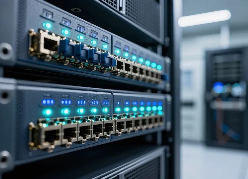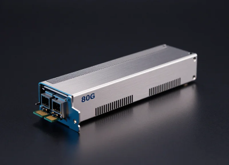
In the era of Generative AI and Large Language Models, bandwidth is no longer the only metric that matters—latency has become the new performance bottleneck. As data centers migrate to 800G, the demand for low-latency optical modules has skyrocketed. This article provides a comprehensive deep dive into the technical specifications, architectural innovations, and deployment strategies for 800G modules designed to minimize delay and maximize throughput.
The Evolution to 800G: Why Latency Matters Now

The shift to 800G modules represents a critical milestone in data center evolution, where the primary objective has moved beyond simple bandwidth expansion to achieving ultra-low latency. As data centers integrate massive AI clusters, the time it takes for data to travel between compute nodes—latency—becomes the defining factor for system performance. Low Latency 800G Modules are engineered to minimize the delay introduced by signal processing and error correction, ensuring that high-performance computing environments can operate at peak efficiency without being throttled by interconnect bottlenecks.
Transitioning from 400G to 800G: A Performance Comparison
| Feature | 400G Modules (Standard) | 800G Modules (Low Latency) |
|---|---|---|
| Throughput | 400 Gbps | 800 Gbps |
| Modulation | 50G/100G PAM4 | 100G/200G PAM4 |
| Primary Driver | Cloud Scale Expansion | AI/ML Training & HFT |
| Latency Focus | Best-effort Delivery | Microsecond Precision |
The Impact of Latency on Modern Applications
In the context of Artificial Intelligence and Machine Learning (AI/ML), training large language models requires thousands of GPUs to work in parallel. These GPUs frequently exchange data via collective communication primitives like All-Reduce. If an 800G optical module introduces even a few extra microseconds of latency, it can cause a 'straggler' effect, where the entire compute cluster waits for a single packet, significantly increasing training time and operational costs. Similarly, in High-Frequency Trading (HFT), a latency advantage measured in nanoseconds can be the difference between a successful trade and a missed opportunity.
- Why is 800G necessary for AI clusters?
AI models are growing exponentially in size, requiring higher bandwidth to move parameters between nodes and lower latency to keep GPU utilization high during synchronization cycles. - How does latency affect power consumption?
Reducing latency often involves optimizing or bypassing certain DSP (Digital Signal Processing) functions, which can also lead to more power-efficient optical module designs like LPO (Linear Drive Pluggable Optics). - What is the role of FEC in 800G latency?
Forward Error Correction (FEC) is essential for data integrity at high speeds but adds processing time. Low-latency 800G modules utilize optimized FEC algorithms or hardware-level acceleration to mitigate this delay.
Architectural Breakdown: DSP-based vs. LPO Modules
Architectural Breakdown: DSP-based vs. LPO Modules
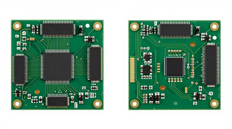
The primary architectural distinction between traditional 800G modules and low-latency alternatives lies in the presence or absence of a Digital Signal Processor (DSP). In a standard 800G transceiver, the DSP acts as a signal regenerator, performing complex tasks such as Clock and Data Recovery (CDR), equalization, and Forward Error Correction (FEC) within the module itself. In contrast, Linear Drive Pluggable Optics (LPO) eliminate the DSP entirely, utilizing a direct analog path where the high-quality signal from the host ASIC's SerDes is amplified and converted to light without digital re-timing. This 'linear drive' approach is the breakthrough that enables the sub-nanosecond latency required for modern AI clusters.
The Traditional DSP Approach
DSP-based modules are designed for robustness and interoperability. By including a DSP chip, the module can compensate for signal degradation across long optical fibers or poor-quality host PCB traces. However, this comes at a high cost: every signal must be sampled, processed, and re-transmitted. At 800G speeds, the DSP chip alone can account for nearly 50% of the module's power consumption and adds significant 'processing delay' (latency) to the data path, which becomes a bottleneck in synchronized AI training workloads.
The LPO (Linear Drive) Innovation
LPO modules leverage the improving capabilities of host Switch/NIC ASICs. Since the host's SerDes (Serializer/Deserializer) can now produce extremely clean signals, the LPO module only needs high-linearity TIA (Transimpedance Amplifier) and Driver chips to maintain signal integrity. By removing the DSP, LPO modules achieve 'bent-pipe' latency—essentially the speed of light through the components—reducing the delay from approximately 100ns in DSP modules to less than 1ns in the module electronics.
| Feature | DSP-based 800G | LPO 800G (Linear Drive) |
|---|---|---|
| Latency | ~100ns (High) | <1ns (Ultra-Low) |
| Power Consumption | 16W - 22W | 8W - 12W |
| Signal Processing | Active Re-timing/FEC | Linear Analog Pass-through |
| Max Reach | Up to 10km (SMF) | Typically <500m (SR/DR) |
| Cost Structure | Higher (DSP is expensive) | Lower (Simplified BoM) |
Key Design Implications
- Can LPO replace all DSP modules?
No. LPO is ideal for short-reach high-density environments like AI back-ends (Intra-rack or Inter-rack). For long-haul data center interconnects (DCI), the signal compensation provided by a DSP is still mandatory. - Does LPO increase the burden on the switch?
Yes. Because the module lacks a DSP to 'clean' the signal, the host switch must have high-performance SerDes and very precise PCB layout designs to ensure signal integrity across the interface. - How does power reduction affect cooling?
LPO modules reduce heat dissipation by roughly 40-50%, allowing for higher port density and lower cooling costs in 800G-ready data centers.
Key Technical Specifications of 800G Transceivers
Key Technical Specifications of 800G Transceivers
The performance of 800G transceivers is primarily defined by their ability to maintain signal integrity at extreme frequencies, achieved through the shift to 112G SerDes (Serializer/Deserializer) electrical lanes and advanced PAM4 modulation. These specifications are not merely speed upgrades; they represent a fundamental change in how data is encoded and error-corrected, directly influencing the end-to-end latency profile of AI and high-performance computing (HPC) fabrics.
112G SerDes: Doubling the Lane Rate
At the heart of 800G architecture is the 112G SerDes, which allows the module to interface with the host switch using 8 lanes of 112 Gbps each. This transition from 400G's 56G SerDes necessitates tighter tolerances for insertion loss and crosstalk. While 112G SerDes enables higher density, it requires sophisticated equalization within the DSP (Digital Signal Processor) to recover signals across the electrical interface, which can introduce incremental processing delays if not optimized for low-latency paths.
PAM4 Modulation and Spectral Efficiency
800G modules utilize 4-level Pulse Amplitude Modulation (PAM4) to carry two bits per symbol. This doubling of spectral efficiency compared to traditional NRZ (Non-Return-to-Zero) is essential for achieving 800G throughput within limited bandwidth windows. However, PAM4 has a lower Signal-to-Noise Ratio (SNR), making the signal more susceptible to noise. This vulnerability is the primary reason why heavy Forward Error Correction (FEC) is standard in most 800G implementations.
The FEC Latency Penalty
Forward Error Correction (FEC) is indispensable for 800G PAM4 links to achieve a Bit Error Rate (BER) of 1E-15 or better. The most common scheme, KP4 FEC (RS-FEC), adds a deterministic latency of approximately 100ns to 150ns per link. In latency-sensitive AI training clusters, where thousands of links are traversed, these nanoseconds accumulate. Low-latency 800G modules, particularly LPO variants, aim to minimize this by relying on the host ASIC for FEC or using lighter, 'FEC-lite' algorithms where the physical layer allows.
| Specification | Standard 800G (DSP-Based) | Low Latency 800G (LPO/LGD) |
|---|---|---|
| Electrical Lane Rate | 112 Gbps (8 Lanes) | 112 Gbps (8 Lanes) |
| Modulation Scheme | PAM4 | PAM4 |
| Processing Latency | ~100ns - 250ns | < 10ns (Near-Zero) |
| Power Consumption | 16W - 20W | 8W - 12W |
| Error Correction | Internal DSP FEC | Host-Based/External FEC |
- Does 800G always require FEC?
Yes, because the Signal-to-Noise Ratio (SNR) of PAM4 at 112G is too low to guarantee error-free transmission without mathematical correction, though the location of FEC processing can vary. - How does 112G SerDes affect reach?
Higher frequencies experience more attenuation, typically limiting passive copper (DAC) reach to 1-2 meters and requiring active optical cables (AOC) or transceivers for longer spans. - What is the role of the DSP in 800G latency?
The DSP performs analog-to-digital conversion, equalization, and FEC; each of these steps requires clock cycles that add to the total latency of the module.
Form Factors: OSFP vs. QSFP-DD800
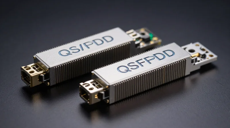
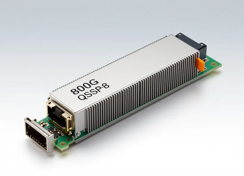
The transition to 800G connectivity is governed by two primary form factors: OSFP (Octal Small Form-factor Pluggable) and QSFP-DD800 (Quad Small Form-factor Pluggable Double Density). While both support 800Gbps throughput using 112G SerDes, their physical architecture dictates the thermal efficiency and signal integrity headroom available for low-latency technologies like LPO. Choosing between them requires balancing the need for legacy compatibility against the rigorous power demands of high-frequency AI/ML clusters.
OSFP: Optimized for Thermal Headroom
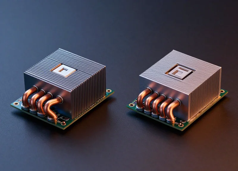
The OSFP form factor was designed specifically with high-power 800G and future 1.6T transitions in mind. Its slightly larger footprint allows for an integrated heat sink directly on the module, which significantly improves airflow and heat dissipation. In low-latency environments where high-speed SerDes operate at peak performance, maintaining lower operating temperatures is critical to prevent thermal throttling and bit-error rate (BER) spikes that would otherwise trigger latency-inducing FEC corrections.
QSFP-DD800: Density and Backward Compatibility
The QSFP-DD800 focuses on maintaining backward compatibility with previous QSFP28 and QSFP56 standards. This allows network operators to upgrade to 800G without discarding existing cabling infrastructure or switch layouts. However, because it lacks the integrated heat sink of the OSFP, it relies on the switch chassis for cooling. This creates a higher power density challenge, making it essential to use low-power LPO or optimized DSP modules to ensure the module stays within the thermal limits of the port cage.
| Feature | OSFP | QSFP-DD800 |
|---|---|---|
| Max Power Rating | Up to 30W (supports 1.6T future) | Up to 25W |
| Thermal Management | Integrated Heat Sink | External Heat Sink (Cage-based) |
| Backward Compatibility | Requires Adapter | Native with QSFP/QSFP-DD |
| Suitability for LPO | High (Better signal integrity) | Moderate (Dense, heat-sensitive) |
The Role of Form Factors in Latency-Sensitive Switching
For low-latency applications like High-Frequency Trading (HFT), the OSFP is often preferred because its thermal efficiency allows the transceiver to maintain a stable electrical-to-optical conversion without the interference caused by excessive heat. Conversely, in hyperscale data centers where port density is the primary driver, QSFP-DD800 allows for a seamless transition. The choice ultimately impacts the choice of internal components; for instance, the extra space in OSFP makes it a prime candidate for the larger, more sensitive components found in early-generation Linear Drive (LPO) solutions.
- Can OSFP and QSFP-DD800 interoperate?
Yes, provided the fiber connectors (MPO-16 or dual LC) and modulation (PAM4) match, OSFP and QSFP-DD800 modules can communicate across a link regardless of their different physical shells. - Which form factor is better for AI clusters?
OSFP is generally favored for AI clusters due to its superior power handling (30W+), which is necessary for the high-intensity data processing and cooling requirements of GPU-to-GPU interconnects. - Does the form factor directly change latency?
Not directly, but indirectly. OSFP's better thermal profile can lead to lower BER, reducing the frequency of FEC-induced delays and retransmissions.
Signal Integrity and Power Consumption Challenges

The Intersection of Signal Fidelity and Power Efficiency
Achieving low latency in 800G modules requires a delicate balance between preserving signal integrity at 112G-per-lane speeds and minimizing the power-hungry processing required to correct data errors. As signal frequency increases, insertion loss and electromagnetic interference (EMI) become more aggressive, often necessitating heavy Digital Signal Processing (DSP) and Forward Error Correction (FEC) algorithms that inherently add nanoseconds of latency. For data center operators, the challenge lies in choosing a module architecture that satisfies the reach requirements without exceeding thermal envelopes or latency budgets.
Signal Degradation at 112G SerDes Speeds
At 800G, the use of 112G SerDes over PAM4 modulation doubles the baud rate compared to 400G, significantly reducing the 'eye' opening of the signal. This makes the link highly susceptible to jitter and chromatic dispersion. To maintain a usable Bit Error Rate (BER) over distances exceeding 500 meters, modules traditionally rely on DSPs to perform equalization. However, these DSPs consume significant power—often 16W to 20W per module—which generates heat that can lead to thermal throttling and subsequent signal instability in high-density OSFP or QSFP-DD ports.
| Feature | DSP-Based 800G | Linear Drive (LPO) 800G |
|---|---|---|
| Power Consumption | 16W - 22W | 8W - 12W |
| Latency Profile | High (DSP + FEC processing) | Ultra-Low (Analog path) |
| Max Reach | Up to 10km (LR4/FR4) | Usually <500m (SR/DR) |
| Signal Integrity | Robust (Active Compensation) | Sensitive (Requires high-quality SerDes) |
The Distance-Latency Dilemma
Distance is the primary enemy of low latency in 800G optics. Longer fiber runs introduce more attenuation, which forces the use of stronger FEC schemes like KP4. These schemes require the module to buffer data blocks to calculate parity, adding a fixed latency penalty. While LPO modules offer a 'bypass' to this processing for short-reach applications, they lack the signal amplification needed for long-haul transmission, effectively bifurcating the 800G market into low-latency/short-reach and standard-latency/long-reach categories.
- How does power consumption affect 800G signal integrity?
High power consumption leads to heat buildup. As temperatures rise, the laser and electronics experience increased thermal noise and frequency drift, which degrades the signal-to-noise ratio (SNR) and increases error rates. - Can FEC be disabled to reduce 800G latency?
In most 800G implementations using 112G SerDes, FEC is mandatory to meet the BER requirements. However, 'light FEC' or custom algorithms can be used in proprietary links to shave off roughly 50-100ns of processing time. - What is the primary cause of signal loss in 800G modules?
The primary causes are high-frequency attenuation in the host PCB and the optical fiber, as well as reflections at the optical connectors, which become more disruptive at the higher baud rates of 800G.
Application Use Case: AI Training Clusters

AI Training Clusters: The Primary Catalyst for Low Latency 800G
In the landscape of large language models (LLMs) and generative AI, the network is often the performance bottleneck; 800G low-latency modules resolve this by providing the massive bandwidth required for the 'All-Reduce' and 'All-to-All' communication patterns typical of distributed training. These modules ensure that thousands of GPUs can act as a single, cohesive computational unit by drastically reducing the time spent waiting for gradient synchronization and data exchange.
Optimizing GPU-to-GPU Communication via RDMA
Low-latency 800G optics are critical when implementing Remote Direct Memory Access (RDMA), which allows GPUs to access the memory of another node directly without involving the host CPU. By utilizing 800G modules within InfiniBand or RoCE v2 (RDMA over Converged Ethernet) architectures, data centers can maintain a strict latency budget. This is essential for preventing 'bubbles' in the training pipeline where expensive GPU resources sit idle while waiting for network packets.
| Feature | InfiniBand (NDR/800G) | RoCE v2 (800G Ethernet) |
|---|---|---|
| Latency Profile | Ultra-low / Deterministic | Low / Configuration Dependent |
| Congestion Control | Credit-based (Lossless) | PFC/ECN (Buffer Management) |
| Typical 800G Form Factor | OSFP (Optimized for Cooling) | QSFP-DD / OSFP |
| Scaling Ecosystem | High-performance specialized AI | Cloud-scale, Interoperable AI |
Mitigating Tail Latency in Massive Scale-Out Fabrics
Scale-out fabrics involving tens of thousands of optical links are highly sensitive to 'tail latency'—the delay experienced by the slowest percentage of packets. 800G modules with optimized DSP (Digital Signal Processing) algorithms and lightweight Forward Error Correction (FEC) help stabilize these outliers. Reducing jitter at the physical layer ensures that distributed training iterations finish concurrently across the entire cluster, preventing a single slow link from degrading the performance of the entire model training session.
Common Questions on 800G in AI Fabrics
- Why is 800G preferred over 400G for AI training?
800G provides double the bandwidth and higher port density, which allows for flatter network topologies (fewer tiers). This reduction in switch hops directly lowers the overall fabric latency and simplifies cable management in massive GPU clusters. - How does 800G latency affect LLM training checkpoints?
Lower latency and higher throughput allow for faster 'checkpointing'—the process of saving the state of a model to storage. This minimizes the interruption time for GPUs, ensuring more efficient recovery and continuous training for models with billions of parameters. - Can LPO (Linear Drive Pluggable Optics) reduce latency in these clusters?
Yes, LPO modules remove the DSP chip entirely, potentially reducing latency by hundreds of nanoseconds per link and significantly lowering power consumption, which is ideal for the short-reach intra-rack connections found in AI back-end networks.
Standardization and Interoperability (IEEE 802.3df)
The Role of IEEE 802.3df in 800G Standardization
The IEEE 802.3df task force is the primary regulatory framework defining the 800 Gb/s and 1.6 Tb/s Ethernet physical layers (PHY), which is essential for low-latency modules as it sets the rigorous performance bounds for electrical lane signaling and error correction. By standardizing 112G and 224G per-lane SERDES (Serializer/Deserializer) rates, IEEE 802.3df ensures that network architects can deploy 800G solutions from different manufacturers while maintaining the predictable latency and deterministic throughput required for modern AI and high-performance computing (HPC) clusters.
Standardization is particularly critical for low-latency modules because these components often employ 'light' Forward Error Correction (FEC) or even bypass certain sub-layers to shave off nanoseconds. Without a unified standard like IEEE 802.3df, these optimizations could lead to signaling mismatches between switches and transceivers, resulting in high Bit Error Rates (BER) and packet retransmissions that would ultimately negate the latency benefits.
Key Performance Metrics and Standards Comparison
| Feature | 800G (IEEE 802.3df) | 400G (IEEE 802.3bs/ck) |
|---|---|---|
| Mainstream Lane Rate | 112G / 224G PAM4 | 56G / 112G PAM4 |
| Total Aggregate Bandwidth | 800 Gbps | 400 Gbps |
| FEC Requirement | Standard & Low-Latency Options | KP4 FEC Standard |
| Max Reach (DAC/AOC) | Up to 2km (SMF) | Up to 500m / 2km |
Multi-Vendor Interoperability and MSAs
Beyond the IEEE standards, Multi-Source Agreements (MSAs) such as OSFP and QSFP-DD800 provide the mechanical and thermal specifications that complement IEEE 802.3df. Interoperability testing ensures that a low-latency 800G module from Vendor A will function seamlessly in a switch manufactured by Vendor B. This 'plug-and-play' capability is vital for hyperscale data centers that must scale rapidly without being locked into a single-vendor supply chain, especially when building out expansive GPU fabrics for AI training.
- Does 800G require a specific type of FEC for low latency?
While IEEE 802.3df defines standard FEC for general use, low-latency 800G modules often utilize custom implementations or 'interleaved' FEC to minimize processing time while still meeting the BER threshold. - How does 224G signaling affect interoperability?
As signaling jumps to 224G per lane, signal integrity becomes more sensitive. IEEE 802.3df provides the electrical specifications to ensure that traces and connectors across different vendors do not introduce excessive jitter or noise. - Can I mix OSFP and QSFP-DD800 modules?
While the electrical signaling defined by IEEE 802.3df is compatible, the physical form factors (OSFP vs. QSFP-DD) are not directly interchangeable without specific adapter ports or matching switch hardware.
Future Outlook: The Road to 1.6T and CPO

The Evolution Toward 1.6T and Co-Packaged Optics
The roadmap for optical interconnects is being accelerated by the insatiable appetite of AI/ML clusters for higher bandwidth and lower tail latency. While 800G modules are currently the gold standard, the industry is already pivoting toward 1.6T (1600G) specifications and Co-Packaged Optics (CPO) to bypass the inherent electrical bottlenecks found in traditional pluggable form factors. This shift is not merely about speed; it is about reducing the physical distance between the switch silicon and the optical engine to ensure signal integrity at unprecedented data rates.
1.6T Ethernet: Scaling for Massive AI Fabrics
1.6T modules, likely utilizing OSFP1600 or QSFP-DD1600 form factors, will double the throughput of current 800G solutions. By moving to 200G-per-lane electrical signaling, 1.6T reduces the number of physical lanes required for massive throughput, which simplifies the physical layer but introduces significant signal integrity challenges. For low-latency applications, the primary benefit of 1.6T is the ability to handle larger data packets and more concurrent streams without the serialization delays associated with lower-speed tiers.
Co-Packaged Optics (CPO): The Ultimate Latency Reducer
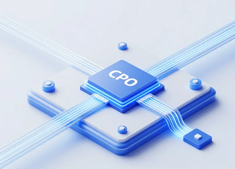
Co-Packaged Optics represents a paradigm shift by integrating the optical engine directly onto the same substrate as the ASIC (Application-Specific Integrated Circuit). By eliminating the long copper traces between the switch chip and the pluggable port on the front panel, CPO can reduce power consumption by up to 30% and significantly lower electrical latency. This architecture is essential for future 3.2T and 6.4T scales where the 'power wall' and 'signal wall' of traditional pluggable modules become insurmountable.
| Feature | 800G Pluggable | 1.6T Pluggable | Co-Packaged Optics (CPO) |
|---|---|---|---|
| Typical Latency | Low (Standard DSP) | Low (200G/lane) | Ultra-Low (Shortest Traces) |
| Power Efficiency | Moderate | High Density | Highest (No Re-timers) |
| Serviceability | Easy (Hot-swappable) | Easy (Hot-swappable) | Complex (Integrated) |
| Primary Use Case | Current AI/HPC | Next-Gen AI Clusters | Future-Scale Fabrics |
Future Roadmap FAQ
- When will 1.6T modules be commercially available?
Initial sampling of 1.6T components has begun, with widespread commercial deployment expected to start in late 2025 and peak in 2026 as AI back-end networks require higher density. - Will CPO replace pluggable modules entirely?
Not immediately. Pluggable modules like 800G and 1.6T will coexist with CPO for several years due to their ease of maintenance. CPO will first dominate ultra-scale internal fabrics where power and latency are the only priorities. - How does 1.6T impact latency compared to 800G?
1.6T reduces 'serialization latency' by processing bits faster. However, because it uses 200G per lane, it requires advanced DSPs which must be carefully designed to keep processing latency at a minimum.
Selecting the right 800G module is a balancing act between power, reach, and latency. As AI workloads continue to push the boundaries of hardware, low-latency 800G modules will remain the backbone of the next-generation data center. Contact our technical team today to find the optimal optical solution for your high-performance network.