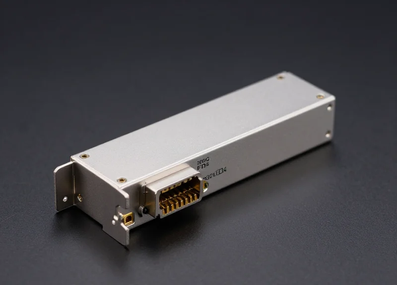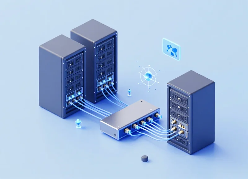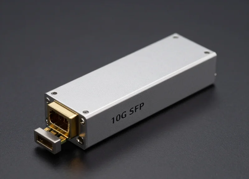
As data centers transition to 400G to meet the demands of AI/ML and cloud computing, selecting the right optical transceiver becomes a critical architectural decision. While the 400G QSFP-DD DR4 is a frontrunner for many, understanding how it stacks up against FR4 and SR8 in terms of latency, power, and total cost is essential for optimizing high-density network environments.
The Evolution of 400G Optical Transceivers
The Evolution of 400G Optical Transceivers
The evolution to 400G signifies more than just a fourfold increase in speed; it represents a fundamental shift in data center architecture designed to support the explosive growth of Artificial Intelligence (AI), Machine Learning (ML), and hyperscale cloud services. Central to this transformation is the QSFP-DD (Quad Small Form-factor Pluggable Double Density) module, which has emerged as the definitive industry standard by offering the highest port density and critical backward compatibility with legacy 100G and 200G infrastructure.
Bridging the Bandwidth Gap: From 100G to 400G
As data traffic continued to surge, traditional 100G NRZ (Non-Return-to-Zero) modulation reached its physical limits regarding power efficiency and spectral density. The move to 400G necessitated the adoption of PAM4 (Four-Level Pulse Amplitude Modulation), which transmits two bits per symbol—effectively doubling the data rate within the same signal bandwidth. This shift allowed network operators to scale up to 12.8Tbps and 25.6Tbps switching capacities, meeting the demands of modern leaf-spine architectures.
| Feature | 100G QSFP28 | 400G QSFP-DD |
|---|---|---|
| Modulation | NRZ | PAM4 |
| Electrical Lanes | 4 x 25G | 8 x 50G |
| Bandwidth per Lane | 25Gbps | 50Gbps |
| Form Factor Compatibility | Standard QSFP | QSFP-DD (Backward Compatible) |
The Dominance of the QSFP-DD Form Factor
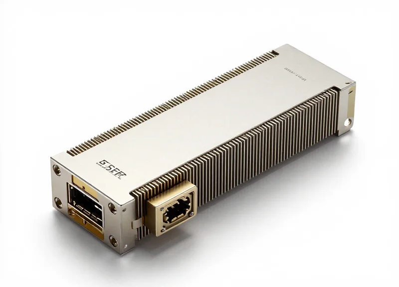
While other form factors like OSFP (Octal Small Form-factor Pluggable) and CFP8 were introduced, QSFP-DD became the industry favorite due to its unique 'double density' approach. By adding a second row of electrical contacts, the QSFP-DD interface increased the number of high-speed electrical lanes from four to eight. This allowed it to maintain the same small footprint as its predecessors, ensuring that 36 ports could be fit into a single 1RU switch chassis, providing an unparalleled density of 14.4Tbps per rack unit.
- Why is backward compatibility important for 400G?
Backward compatibility allows operators to plug existing QSFP28 (100G) or QSFP56 (200G) modules into 400G QSFP-DD ports, protecting previous hardware investments and simplifying the migration path. - How does QSFP-DD compare to OSFP in terms of thermal management?
OSFP modules are slightly larger and feature integrated heat sinks, which provides an edge in cooling; however, QSFP-DD's thermal management has proven sufficient for most 400G applications, including DR4 and FR4. - What role does PAM4 play in 400G evolution?
PAM4 is the enabling modulation technology for 400G, allowing for higher data throughput without requiring the massive increases in fiber count that would be necessary using older NRZ techniques.
Technical Deep Dive: How 400G QSFP-DD DR4 Works
Technical Deep Dive: How 400G QSFP-DD DR4 Works
The 400G QSFP-DD DR4 transceiver is a high-performance optical module designed for 400 Gigabit Ethernet links over up to 500 meters of single-mode fiber. Its operational efficiency stems from the transition to 100G-per-lane optical technology, which significantly simplifies the internal optical path compared to previous generations of multi-lane architectures.
Parallel Single-Mode (PSM4) Architecture
The 'DR4' designation refers to 'Datacenter Reach 4-lane.' Unlike Wavelength Division Multiplexing (WDM) modules that combine multiple signals onto a single fiber pair, the DR4 utilizes a Parallel Single-Mode (PSM4) approach. It employs an MPO-12 or MPO-8 connector to transmit data across four independent fiber pairs simultaneously. Each of these four physical lanes carries a 100Gbps signal. This parallel design is the architectural foundation that enables high-density 'breakout' applications, allowing a single 400G port to be split into four discrete 100G connections.
PAM4 Modulation and the Gearbox System
To achieve 400G throughput within the power and thermal constraints of the QSFP-DD form factor, the DR4 uses 4-level Pulse Amplitude Modulation (PAM4). Internally, the module performs a critical conversion: it receives 8 lanes of 50Gbps electrical signals from the host switch (8x50G PAM4) and uses a Digital Signal Processor (DSP) with a 'gearbox' function to aggregate these into 4 lanes of 100Gbps optical signals. This 100G Lambda technology reduces the component count and improves the overall reliability of the optical engine.
| Technical Parameter | Specification Details |
|---|---|
| Optical Modulation | PAM4 (100G per Lambda) |
| Lane Configuration | 4 x 100Gbps Optical / 8 x 50Gbps Electrical |
| Fiber Connectivity | Parallel Single-Mode Fiber (PSM4) |
| Standard Reach | Up to 500 Meters |
| Connector Type | MPO-12 or MPO-8 (APC) |
| Fiber Type | OS2 Single-Mode Fiber (SMF) |
Key Technical FAQs
- Why is the DR4 reach capped at 500 meters?
The DR4 is intentionally optimized for leaf-to-spine connections within the data center. By limiting the reach to 500m, the module requires less aggressive dispersion compensation in the DSP, leading to lower power consumption and reduced cost compared to 2km (FR4) or 10km (LR4) alternatives. - How does the DR4 facilitate network breakouts?
Because the DR4 uses parallel fiber lanes rather than multiplexed wavelengths, a simple MPO-to-LC breakout cable can physically separate the four 100G streams. This allows the module to interface directly with four 100G-DR or 100G-FR transceivers, providing a seamless migration path from 100G to 400G. - What role does Silicon Photonics play in DR4 modules?
Many DR4 modules utilize Silicon Photonics (SiPh) to integrate the modulator and passive optical components onto a single silicon chip. This integration helps manage the high thermal output of 400G speeds while maintaining the compact QSFP-DD footprint.
400G DR4 vs. FR4: Reach vs. Complexity
400G DR4 vs. FR4: Reach vs. Complexity
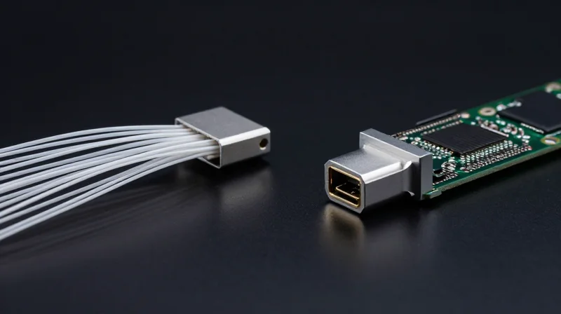
The primary distinction between the 400G DR4 and FR4 modules lies in how they manage optical lanes and fiber resources to achieve their respective distances. While both leverage 100G PAM4 electrical interfaces, the DR4 is optimized for intra-datacenter connections up to 500 meters using parallel fibers, whereas the FR4 employs Coarse Wavelength Division Multiplexing (CWDM) to extend its reach to 2 kilometers over a single pair of fibers. This difference necessitates a strategic choice based on both the physical distance of the link and the underlying cabling infrastructure.
Architectural Differences: PSM4 vs. CWDM4
The 400G DR4 operates on a Parallel Single Mode 4-lane (PSM4) architecture. It transmits four independent 100G signals over four separate fiber pairs, typically requiring an MPO-12 or MPO-16 connector. Conversely, the 400G FR4 utilizes a CWDM4 design, where an internal optical multiplexer combines four different wavelengths—1271nm, 1291nm, 1311nm, and 1331nm—onto a single fiber pair. While the FR4 architecture is more complex due to the need for precise uncooled CWDM lasers and multiplexing components, it significantly reduces the amount of fiber needed for point-to-point 400G transmission.
| Feature | 400G QSFP-DD DR4 | 400G QSFP-DD FR4 |
|---|---|---|
| Maximum Reach | 500 Meters | 2 Kilometers |
| Optical Connector | MPO-12 / MPO-16 | Duplex LC |
| Fiber Requirement | 8-Fibers (4 Tx, 4 Rx) | 2-Fibers (1 Tx, 1 Rx) |
| Laser Source | 4x 1310nm Lasers | 4x CWDM Lasers |
| Breakout Support | Yes (4x100G DR) | No |
Infrastructure and Deployment Considerations
The decision between DR4 and FR4 often hinges on the Total Cost of Ownership (TCO) including cabling. DR4 modules are generally less expensive to manufacture because their optical components are simpler; however, they require high-density MPO cabling, which can be more costly and complex to manage. FR4 modules carry a premium for their CWDM optics, but they operate over standard duplex LC single-mode fiber. This makes FR4 the superior choice for high-radix switching environments where saving duct space and fiber strands is a priority, or where existing 2km fiber runs are already in place.
Strategy and Selection FAQ
- Can 400G DR4 and 400G FR4 interoperate directly?
No. They use fundamentally different optical technologies (Parallel fibers vs. Wavelength Multiplexing) and incompatible connector types, making direct interoperability impossible. - Which module is better for breakout applications?
The 400G DR4 is designed specifically for breakout applications, allowing a single 400G port to connect to four individual 100G DR modules. The FR4 does not support this functionality due to its multiplexed nature. - Is the power consumption different between DR4 and FR4?
Generally, FR4 modules consume slightly more power than DR4 due to the additional circuitry required for wavelength multiplexing and the more complex laser drivers, though both typically fall within the 10-12W range for the QSFP-DD form factor.
400G DR4 vs. SR8: The Short-Reach Multi-mode Battle
400G DR4 vs. SR8: The Short-Reach Multi-mode Battle
The decision between 400G SR8 and DR4 represents a fundamental choice between Multi-mode Fiber (MMF) and Single-mode Fiber (SMF) for data center leaf-spine links. While SR8 leverages legacy multi-mode advantages for distances up to 100m, DR4 provides a more scalable 500m reach using 100G-per-lane technology, effectively bridging the gap between short-reach efficiency and long-term infrastructure flexibility.
Technical Specifications and Fiber Density
The primary technical differentiator lies in the lane architecture. SR8 utilizes eight lanes of 50G PAM4, which requires an MPO-16 or MPO-24 connector to manage the 16 fibers (8 transmit, 8 receive). In contrast, DR4 uses four lanes of 100G PAM4, requiring only 8 fibers via an MPO-12 connector. This reduction in fiber count per link can significantly impact cable management in high-density environments.
| Feature | 400G QSFP-DD SR8 | 400G QSFP-DD DR4 |
|---|---|---|
| Transmission Reach | 70m (OM3) / 100m (OM4/OM5) | 500m |
| Fiber Type | Multi-mode (MMF) | Single-mode (SMF) |
| Optical Lane Rate | 8 x 50G PAM4 | 4 x 100G PAM4 |
| Connector Type | MPO-16 / MPO-24 | MPO-12 |
| Fiber Count | 16 Fibers | 8 Fibers |
Cost Implications: Transceivers vs. Cabling
Historically, SR8 modules have been cheaper to manufacture because they use VCSEL (Vertical-Cavity Surface-Emitting Laser) technology, which is less expensive than the Silicon Photonics or DML lasers required for DR4. However, the total cost of ownership (TCO) calculation must include the cabling. SR8's requirement for 16 fibers per link doubles the fiber density compared to DR4. For new greenfield deployments, the lower cost of single-mode cabling and the ability for DR4 to support longer runs often offsets the higher initial price of the SMF transceivers.
- When should I choose SR8 over DR4?
SR8 is most effective in brownfield environments where OM3 or OM4 multi-mode fiber infrastructure is already installed and the distances are strictly under 100 meters. - Why is DR4 considered more future-proof?
DR4 uses single-mode fiber, which has virtually unlimited bandwidth capacity. This allows operators to migrate to 800G or 1.6T in the future without replacing the physical cable plant. - Does SR8 support 4x100G breakout applications?
No. Because SR8 uses 50G lanes, it is designed for 8x50G breakouts. DR4 is the standard choice for breaking out a 400G port into four 100G (DR1) ports.
Latency Analysis for AI and High-Performance Computing

Latency Analysis for AI and High-Performance Computing
In the context of Artificial Intelligence (AI) and High-Performance Computing (HPC), network latency is often the primary bottleneck for distributed training and large-scale parallel processing. For 400G QSFP-DD DR4 and its counterparts, the total latency is no longer dominated solely by the physical length of the fiber; instead, it is significantly influenced by the Digital Signal Processing (DSP) cycles and the Forward Error Correction (FEC) overhead required to process PAM4 signals. While typical fiber propagation latency is roughly 5ns per meter, the electronic processing within a 400G module can add 100ns to 200ns of delay, making the choice of module architecture critical for jitter-sensitive AI fabrics.
The Impact of KP4 FEC and DSP on Signal Processing
The transition from 100G NRZ to 400G PAM4 necessitated the use of KP4 Forward Error Correction (FEC) to achieve a viable Bit Error Rate (BER). This FEC algorithm introduces a fixed processing delay, typically around 100ns to 120ns, which is mandatory for standard 400G Ethernet implementations. For AI clusters using InfiniBand or specialized RDMA over Converged Ethernet (RoCE), this 'FEC penalty' is a constant that architects must account for. The DSP within a DR4 or FR4 module also consumes power and adds a few nanoseconds of latency to compensate for chromatic dispersion and signal degradation, though the DR4’s parallel fiber approach often requires less complex equalization than the WDM-based FR4.
| Module Type | Modulation | DSP Latency (Approx) | FEC Requirement | HPC Suitability |
|---|---|---|---|---|
| 400G DR4 | PAM4 | < 10ns | KP4 Mandatory | High (Parallel lanes) |
| 400G FR4 | PAM4 | 10-15ns | KP4 Mandatory | Medium (WDM overhead) |
| 400G SR8 | PAM4 | < 10ns | KP4 Mandatory | High (Short reach) |
| 400G LPO (Linear) | PAM4 | < 1ns | Host-dependent | Ultra-High (No DSP) |
Emerging Low-Latency Trends: DSP-Lite and LPO
To further reduce latency in AI back-end networks, the industry is exploring Linear Drive Pluggable Optics (LPO). Unlike the standard 400G DR4 which uses a power-intensive DSP to retime and reshape the signal, LPO modules remove the DSP entirely, relying on the host ASIC to handle signal integrity. This can reduce module-level latency to sub-nanosecond levels and cut power consumption by up to 50%. However, for standard deployments where interoperability and 500m reach are required, the 400G DR4 remains the benchmark for balancing reliable signal recovery with a predictable latency profile.
- How much latency does KP4 FEC add to a 400G link?
KP4 FEC typically adds between 100ns and 150ns of latency per link, which is a significant factor in large-scale AI training clusters where thousands of nodes communicate. - Does the 400G DR4 have lower latency than the FR4?
While the difference is marginal (often <5ns), DR4 can have slightly lower latency because it avoids the multiplexing/demultiplexing stages required for the CWDM wavelengths in FR4. - Why is latency critical for RDMA and InfiniBand?
AI workloads rely on frequent synchronization (All-Reduce operations). High latency or jitter in the optical link increases the idle time for GPUs, directly reducing the efficiency of the entire cluster.
Power Consumption: Optimizing the Energy Envelope
Power Consumption: Optimizing the Energy Envelope
The 400G QSFP-DD DR4 module typically operates within a power envelope of 10W to 12W, positioning it as a highly efficient choice for high-density architectures. By leveraging a 4-lane parallel design and silicon photonics integration, the DR4 minimizes the electrical-to-optical conversion overhead that often plagues more complex multiplexed modules. This efficiency is critical for modern data centers where power density per rack is a primary constraint on scalability and cooling infrastructure.
Comparative Power Metrics Across 400G Standards
| Module Type | Typical Power Draw (Watts) | Reach / Medium | Thermal Complexity |
|---|---|---|---|
| QSFP-DD DR4 | 10W - 12W | 500m / PSM4 SMF | Low |
| QSFP-DD SR8 | 10W - 12W | 100m / MPO-16 MMF | Moderate |
| QSFP-DD FR4 | 12W - 14W | 2km / CWDM4 SMF | High (CWDM Mux/Demux) |
| QSFP-DD LR4 | 13W - 15W | 10km / LWDM SMF | High (TEC Required) |
| QSFP-DD ZR | 16W - 20W+ | 120km+ / Coherent | Extreme (DSP Intensive) |
While the raw wattage of DR4 and SR8 appear similar on paper, the DR4 holds a significant advantage in thermal dissipation and reliability. The use of fewer lasers (four vs. eight in SR8) and the ability to utilize silicon photonics reduces the heat density within the module casing. This lower thermal load directly translates to a reduced burden on the data center's air conditioning units (CRACs) and allows for higher port density without risking thermal throttling of the host switch's ASICs.
The Hidden Costs: OpEx and Cooling Capacity
Choosing a module with a higher power profile, such as the FR4 or ZR, introduces a 'power tax' that extends beyond the electricity bill. For every extra watt consumed by the optic, additional power is required to drive chassis fans at higher RPMs to maintain airflow. Over a 5-year lifecycle in a 128-port spine switch, the 2-3W difference between a DR4 and an FR4 can result in thousands of dollars in excess operational expenditure and a shortened Mean Time Between Failure (MTBF) for the surrounding hardware.
FAQ: Efficiency and Thermal Management
- How does DR4 compare to SR8 in power efficiency?
Both generally consume 10-12W, but DR4 is often more stable because it uses four 100G lanes instead of eight 50G lanes, simplifying the internal DSP and thermal dissipation. - Why do 400G FR4 modules consume more power than DR4?
FR4 requires more complex CWDM lasers and multiplexing components that must operate within tighter temperature tolerances, often requiring more sophisticated internal cooling control. - Can high power consumption impact signal integrity?
Yes. Excessive heat within the QSFP-DD form factor can cause frequency drift in lasers and increased noise in the DSP, potentially leading to higher Bit Error Rates (BER) if not properly cooled.
Total Cost of Ownership (TCO) Breakdown

Total Cost of Ownership (TCO) Breakdown
Evaluating the total cost of ownership for 400G QSFP-DD DR4 requires a holistic view that balances initial capital expenditures (CAPEX) against the cumulative operational costs (OPEX) of power, cooling, and future network scalability over a standard 3 to 5-year lifecycle. While SR8 optics often appear cheaper on a per-unit basis, the shift toward single-mode fiber (SMF) driven by DR4 and FR4 standards frequently yields a lower TCO in hyperscale environments due to reduced cabling bulk and better paths for 800G and 1.6T upgrades.
CAPEX Analysis: Modules and Cabling Infrastructure
CAPEX is divided between the transceiver modules and the physical layer infrastructure. DR4 utilizes parallel single-mode fiber, which is more expensive than the duplex fiber used by FR4 but significantly more future-proof than the multi-mode fiber (MMF) required for SR8. In large-scale deployments, the cost of MPO-16 connectors and high-grade OM4/OM5 fiber for SR8 can quickly erode the savings gained from cheaper transceiver units.
| Cost Component | QSFP-DD SR8 (MMF) | QSFP-DD DR4 (SMF) | QSFP-DD FR4 (SMF) |
|---|---|---|---|
| Module Unit Price | Lowest | Moderate | High |
| Cabling Media Cost | High (OM4/OM5) | Moderate (Parallel SMF) | Lowest (Duplex SMF) |
| Connector Type | MPO-16 | MPO-12 | LC Duplex |
| Relative CAPEX | Baseline (1.0x) | 1.2x - 1.4x | 1.5x - 1.8x |
OPEX Considerations: Power, Cooling, and Maintenance
Operational expenses are dominated by power consumption. A 400G QSFP-DD DR4 module typically draws between 10W and 12W. When scaled across thousands of ports, even a 1W difference per module translates to massive variations in utility bills and cooling infrastructure requirements. Furthermore, DR4 modules often benefit from more mature Silicon Photonics integrations, which can lead to higher reliability and lower replacement rates over a 5-year window compared to complex VCSEL-based SR8 arrays.
Lifecycle ROI: The 3-5 Year Outlook
When projecting costs over five years, the 'Day 2' advantages of DR4 become clear. Because DR4 uses single-mode fiber, organizations can transition to 800G (DR8) or higher speeds without re-pulling fiber through the raceways. This 'install-once' philosophy for the physical layer is the primary driver for DR4 adoption in Tier 1 and Tier 2 data centers, as the labor cost of replacing MMF cabling often exceeds the initial savings of the SR8 hardware.
- How does fiber type affect TCO in the long run?
Single-mode fiber (used by DR4) supports much higher bandwidth and longer distances. While initial parallel SMF cabling is more complex than duplex, it eliminates the need for expensive 'forklift upgrades' when moving to 800G or 1.6T architectures. - Is SR8 ever the more cost-effective choice?
SR8 is often more cost-effective for small-scale enterprise data centers or 'islands' of compute where the reach is strictly under 100 meters and there is no immediate plan to migrate to a 100G-per-lane signaling architecture. - What is the impact of Silicon Photonics on DR4 costs?
Silicon Photonics allows for the integration of multiple optical components onto a single chip, which improves manufacturing yield and reliability, eventually driving the CAPEX of DR4 closer to that of legacy multi-mode solutions.
Cabling Infrastructure and Breakout Capabilities
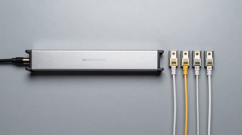
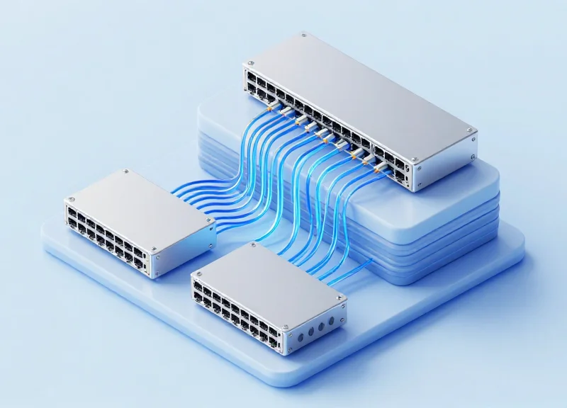
The primary advantage of the 400G QSFP-DD DR4 over alternatives like FR4 is its inherent support for breakout configurations, allowing a single 400G port to be split into four independent 100G channels. This capability is enabled by its Parallel Single Mode (PSM) design, which uses four parallel lanes of 100G PAM4 signals over eight fibers (four transmit and four receive). By leveraging MPO-12 or MPO-8 connectors, data center operators can maximize the utility of their spine-leaf fabric, connecting a single high-speed spine port to four separate 100G leaf switches, thereby reducing the physical footprint and the cost per gigabit significantly.
Cabling Infrastructure: Parallel vs. WDM
Infrastructure choices are often dictated by existing cabling plants. While the 400G FR4 uses Wavelength Division Multiplexing (WDM) to send signals over a single pair of fibers, the DR4 requires parallel fiber cabling. This shift to MPO-based single-mode fiber (SMF) infrastructure is an investment in future-proofing, as it aligns with the roadmap for 800G and 1.6T systems which will continue to rely on parallel optical paths for breakout and low-latency performance.
| Feature | 400G QSFP-DD DR4 | 400G QSFP-DD FR4 | 400G QSFP-DD SR8 |
|---|---|---|---|
| Cabling Type | MPO-12 Single Mode (8 Fibers) | LC Duplex Single Mode (2 Fibers) | MPO-16 Multi-mode (16 Fibers) |
| Breakout Mode | 4x100G (DR1/FR1) | Not Native (Requires Mux) | 8x50G or 2x200G |
| Max Distance | 500m | 2km | 100m (OM4) |
| Main Use Case | Spine-Leaf Breakout / High Density | Spine-to-Spine / Long Reach | Intra-Rack / Short Reach |
Efficiency in Leaf-Spine Architectures
In modern hyperscale environments, the 400G DR4 module acts as a force multiplier for port utilization. By utilizing a breakout cable (MPO-12 to 4x Duplex LC or 4x SN/MDC connectors), operators can eliminate the need for intermediate patch panels in some configurations. This direct-connect breakout method reduces insertion loss and points of failure while allowing for a staggered upgrade path where the core network is 400G-ready but access layers remain at 100G.
Infrastructure FAQ
- Can 400G DR4 interoperate with 100G QSFP28 modules?
Yes, a 400G DR4 port can break out to four 100G-DR or 100G-FR modules (QSFP28) as long as the 100G modules support PAM4 modulation. It is not compatible with legacy 100G-LR4 or SR4 modules using NRZ modulation without a gearbox. - What is the impact on cable management?
DR4 requires MPO cabling, which is denser than LC duplex but requires careful management of polarity and fiber cleanliness. Using MPO-12 simplifies the number of connectors at the faceplate compared to older multi-lane standards. - Is DR4 cost-effective for short distances?
Yes, because it uses fewer lasers (4) compared to SR8 (8) and avoids the complex optical mux/demux components of FR4, making it the price-performance 'sweet spot' for links up to 500 meters.
Future-Proofing: Transitioning to 800G and 1.6T
The Strategic Bridge to Next-Generation Speeds
Transitioning from 400G to higher speeds like 800G and 1.6T is fundamentally about aligning lane rates and scaling parallel fiber counts rather than replacing the entire architectural framework. The 400G QSFP-DD DR4 module, utilizing four lanes of 100G PAM4 signaling, provides a direct technological path to 800G (typically 8x100G in early iterations). By adopting DR4 now, data center operators mature their 100G-per-lane ecosystems and MPO-based cabling plants, making the eventual jump to 800G a matter of modular upgrades rather than a fundamental infrastructure overhaul.
Parallel Evolution: From 4x100G to 8x200G
As the industry moves toward 1.6T, the focus shifts to 200G-per-lane SerDes. The experience gained in managing the signal integrity and thermal density of 400G DR4 modules is critical for this transition. Unlike WDM-based alternatives (such as FR4) which require complex multiplexing components, the DR series' reliance on parallel fibers (PSM4) matches the physical layer requirements of high-radix switches. This parallel approach ensures that the MPO-12 or MPO-16 cabling installed for 400G DR4 remains relevant as it can be repurposed for 800G DR8 or even 1.6T breakout configurations.
| Feature | 400G DR4 | 800G DR8 | 1.6T (Planned) |
|---|---|---|---|
| Lane Rate | 100G PAM4 | 100G PAM4 | 200G PAM4 |
| Fiber Type | Parallel SMF (8 fibers) | Parallel SMF (16 fibers) | Parallel SMF (16 fibers) |
| Connector | MPO-12 / MPO-16 | MPO-16 / Dual MPO-12 | MPO-16 / MPO-32 |
| Main Benefit | Established 100G Ecosystem | Double Density / Same Lane Rate | Next-Gen 200G SerDes Alignment |
Future-Proofing FAQ
- Will 400G DR4 modules work with 800G switches?
Yes, through breakout cables and backward compatibility in QSFP-DD800 ports, 400G DR4 modules can typically interface with 800G ports operating in 2x400G mode. - Does the fiber plant need to be replaced for 1.6T?
If using high-quality OS2 single-mode fiber with MPO-16 connectors for 400G DR4 deployments, the underlying glass remains viable for 1.6T, though transceiver modules and potentially patch panels may need upgrading to support 200G-per-lane signal integrity. - Why choose DR4 over FR4 for long-term roadmaps?
DR4 uses parallel optics which facilitates easy breakout to 100G servers. As switch radix increases, the ability to break down a high-speed port (800G/1.6T) into multiple 100G or 400G legs is more efficient with parallel fiber (DR) than with multiplexed fiber (FR).
Choosing the right 400G module requires balancing immediate hardware costs with long-term energy efficiency and performance needs. The QSFP-DD DR4 offers a compelling mix of low latency and breakout flexibility for modern workloads. Ready to optimize your data center? Contact our engineering team for a customized 400G migration roadmap.