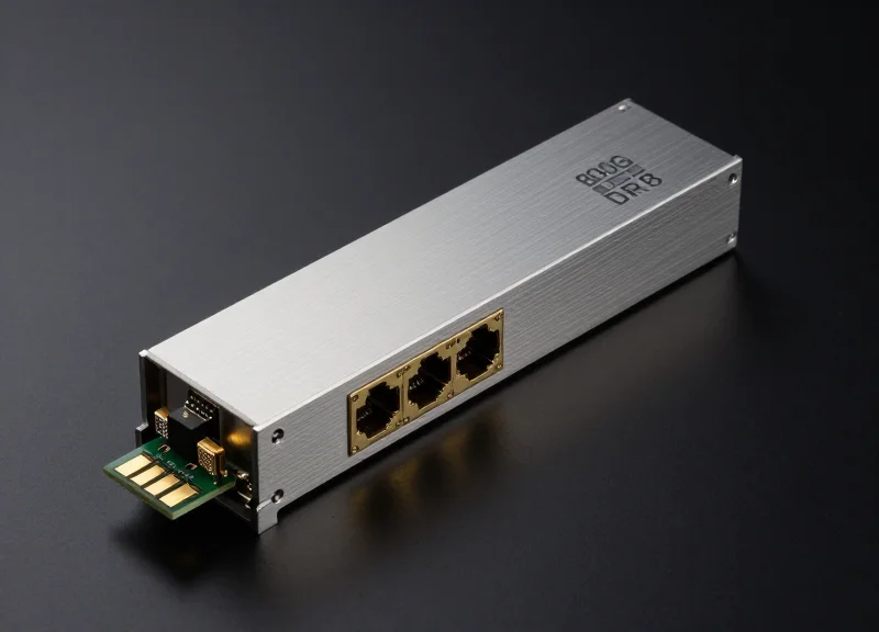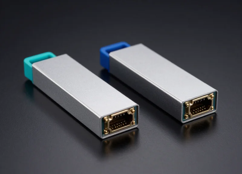
As data demands surge, the need to push 100G speeds beyond the standard 10km limit has led to the development of specialized ER4 and ZR4 standards. This article dives into the engineering marvels that allow for 40km to 80km reach without the need for expensive external amplification, providing a roadmap for high-speed network expansion.
The Evolution of 100G Long-Reach Standards

The Evolution of 100G Long-Reach Standards
The transition of 100G Ethernet from localized data center environments to expansive metro-area networks was driven by the necessity to bridge the gap between 10km and 80km distances without costly intermediate amplification. While early 100G standards like SR4 and LR4 satisfied intra-data center and campus-level requirements, the emergence of ER4 (Extended Reach) and ZR4 (Ultra-Long Reach) represents a fundamental shift in optical engineering, utilizing advanced wavelength division multiplexing (WDM) and high-sensitivity receivers to overcome signal attenuation over long-haul fiber spans.
Tracing the Reach: From SR4 to ZR4
Initially, 100G deployments relied on multi-mode fiber for short reaches (SR4) or standard single-mode fiber for 10km reaches (LR4). As hyperscale data centers began interconnecting across cities, the industry hit a 'distance wall.' The following table illustrates how standards evolved to meet these increasing distance requirements.
| Standard | Target Reach | Fiber Type | Optical Interface |
|---|---|---|---|
| 100G-SR4 | 100m | MMF (OM4) | 850nm (4x25G Parallel) |
| 100G-LR4 | 10km | SMF | 1310nm (LWDM) |
| 100G-ER4 | 40km | SMF | 1310nm (LWDM + APD/SOA) |
| 100G-ZR4 | 80km | SMF | 1310nm (LWDM + Amplification) |
Technological Milestones in Long-Reach Design
To achieve 40km and 80km reaches, engineers had to move beyond simple PIN photodiodes. ER4 modules introduced Avalanche Photodiodes (APD) or integrated Semiconductor Optical Amplifiers (SOA) to enhance sensitivity. For ZR4, the challenge intensified; achieving 80km typically requires sophisticated forward error correction (FEC) and optimized LAN-WDM laser grids to minimize dispersion and maintain signal integrity over extreme distances. This evolution signifies the maturation of 100G from a 'local' technology to a backbone 'interconnect' technology.
- Why wasn't LR4 enough for metro networks?
100G-LR4 is limited to 10km due to its link budget. Metro interconnects often exceed 30km, requiring the higher output power and receiver sensitivity found in ER4 and ZR4. - What is the primary difference between ER4 and ZR4?
The primary difference is the power budget and the internal amplification; ZR4 is specifically designed to hit the 80km threshold, often utilizing more aggressive FEC and amplification stages than standard ER4. - Do these long-reach modules use the same cabling?
Yes, they all utilize standard G.652 Single-Mode Fiber (SMF), though the quality of the fiber and the number of splices significantly impact the achievable reach for ZR4.
Technical Architecture of 100G ER4
Core Architecture: The 4-Lane LAN-WDM Grid
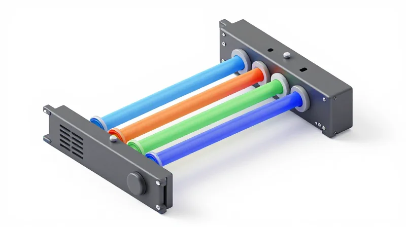
The 100G ER4 transceiver operates by multiplexing four distinct wavelengths on the LAN-WDM grid (IEEE 802.3ba) within the 1310nm band. These wavelengths—1295.56nm, 1300.05nm, 1304.58nm, and 1309.14nm—are spaced at approximately 4.5nm to minimize dispersion and interference. Each lane carries a 25.78 Gbps signal (NRZ modulation), which, when combined, provides a total throughput of 103.1 Gbps. This architecture allows for efficient transmission over Standard Single-Mode Fiber (G.652) without the need for complex dispersion compensation required at higher wavelength bands.
Critical Components: EML Transmitters and APD Receivers
To achieve a 40km reach, the hardware requirements for ER4 are significantly more stringent than those for standard 10km LR4 modules. The primary difference lies in the transmitter power and receiver sensitivity.
| Component | 100G LR4 | 100G ER4 |
|---|---|---|
| Transmitter Type | DML or EML | EML (Electro-absorption Modulated Laser) |
| Receiver Type | PIN Photodiode | APD (Avalanche Photodiode) |
| Receiver Sensitivity | Approx. -10.6 dBm | Approx. -20.9 dBm |
| Maximum Reach | 10km | 30km (40km with FEC) |
The Role of the Avalanche Photodiode (APD)
The defining technical feature of the 100G ER4 is the use of an Avalanche Photodiode (APD) receiver. Unlike the PIN photodiodes used in shorter-reach modules, APDs utilize the 'impact ionization' effect to create an internal gain. This gain significantly enhances the receiver sensitivity, allowing the module to detect the faint optical signals that remain after traveling 40km through fiber, where signal attenuation typically exceeds 15-18 dB.
EML Laser Performance
On the transmit side, Electro-absorption Modulated Lasers (EML) are mandatory. EMLs provide a stable, high-power signal with extremely low 'chirp' (wavelength fluctuation during modulation). This stability is vital for maintaining signal integrity over long distances where chromatic dispersion could otherwise lead to significant Bit Error Rate (BER) degradation.
- Why is the LAN-WDM grid used instead of CWDM?
LAN-WDM uses tighter spacing in the 1310nm window where fiber dispersion is near zero, which is essential for high-speed signals over distances like 40km. CWDM spacing is too wide and spans wavelengths where dispersion is higher. - What is the power consumption of a typical 100G ER4 module?
Due to the inclusion of a Thermo-Electric Cooler (TEC) to stabilize the EML lasers and the high-gain APD circuitry, these modules typically consume between 3.5W and 4.5W. - Is FEC (Forward Error Correction) required for 40km?
Technically, 100G ER4 can reach 30km without FEC. To achieve the full 40km specification while maintaining a clean BER, Host-FEC (KR4 FEC) is generally required on the switch or router ports.
Decoding the 100G ZR4 Specification
Decoding the 100G ZR4 Specification
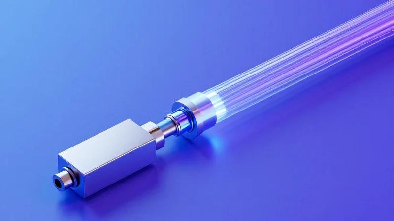
100G ZR4 is a specialized optical specification designed to extend the reach of 100Gbps Ethernet to 80km over standard G.652 single-mode fiber without the need for external optical amplifiers or dispersion compensation. By integrating a Semiconductor Optical Amplifier (SOA) directly into the transceiver, ZR4 overcomes the attenuation limits that restrict standard 100G interfaces like ER4 to shorter distances. It functions by multiplexing four 25G channels onto a LAN-WDM grid, providing a cost-effective solution for metro-edge and data center interconnect (DCI) applications where fiber resources are limited.
The Role of the Integrated Semiconductor Optical Amplifier (SOA)
The defining technical feature of the 100G ZR4 module is the inclusion of a Semiconductor Optical Amplifier (SOA) on the receiver side. In standard long-reach optics like 100G ER4, an Avalanche Photodiode (APD) is used to improve sensitivity for distances up to 40km. However, at 80km, the link budget typically requires a loss tolerance of roughly 28dB. The SOA acts as a pre-amplifier, boosting the incoming 4-lane LAN-WDM signal before it reaches the PIN photodetector. This allows the receiver to maintain a high Signal-to-Noise Ratio (SNR) despite the significant path loss accumulated over ultra-long distances.
| Feature | 100G ER4 | 100G ZR4 |
|---|---|---|
| Maximum Transmission Distance | 40km | 80km |
| Receiver Architecture | APD (Avalanche Photodiode) | SOA + PIN Receiver |
| Optical Link Budget | ~18.5dB | ~28dB |
| Typical Power Consumption | Max 4.5W | Max 6.0W |
| Laser Type | 4x25G EML | 4x25G EML |
Wavelength Management and Dispersion Control
100G ZR4 utilizes the LAN-WDM wavelength grid (1295.56nm, 1300.05nm, 1304.58nm, and 1309.14nm) within the O-band. Operating in the O-band is strategic because it is the region of near-zero chromatic dispersion for G.652 fiber. While the fiber attenuation is slightly higher in the O-band compared to the C-band (used in DWDM), the lack of dispersion allows ZR4 to maintain signal integrity over 80km without the complexity of digital signal processing (DSP) or Coherent detection, keeping the hardware simpler and less power-intensive than 100G Coherent alternatives.
- Why does ZR4 consume more power than LR4/ER4?
The integrated SOA requires additional electrical power for the gain medium and thermal stabilization, typically increasing the total module power budget to around 5.5W to 6W. - Is a specialized host required for ZR4?
ZR4 uses the standard QSFP28 form factor, but the host switch must support the higher power envelope (Power Class 4 or higher) required by the SOA-integrated module. - Can ZR4 be used for distances shorter than 80km?
Yes, but if the link is very short (e.g., under 10-20km), optical attenuators may be necessary to prevent the high-gain receiver from saturating or damaging the SOA/PIN assembly.
The Role of APD and SOA in Signal Integrity

The Role of APD and SOA in Signal Integrity
In ultra-long 100G transmission, the primary challenge is overcoming fiber attenuation that reduces optical power levels below the detection threshold of standard PIN receivers. Signal integrity in these environments depends on the transceiver's ability to maximize receiver sensitivity while minimizing the impact of noise. 100G ER4 modules typically utilize Avalanche Photodiodes (APD) to provide internal gain at the receiver stage, whereas 100G ZR4 modules leverage Semiconductor Optical Amplifiers (SOA) to boost the signal optically before it reaches the detector. Both components are critical for achieving the 40km to 80km reach required for modern metro and data center interconnects.
APD: Precision Detection for 40km Reach
The Avalanche Photodiode is the standard choice for 100G ER4. Unlike a conventional PIN diode, an APD uses the impact ionization process—often referred to as the 'avalanche effect'—to provide internal current gain. When a photon strikes the APD, it creates an electron-hole pair which is then accelerated by a high reverse-bias voltage, colliding with other atoms to create a cascade of carriers. This gain significantly improves the receiver sensitivity, allowing the ER4 module to detect signals that have been attenuated by up to 18dB over 40km of single-mode fiber without requiring external amplification.
SOA: Bridging the 80km Gap in ZR4
To extend reach to the 80km ZR4 specification, the inherent gain of an APD is often insufficient. Instead, ZR4 modules incorporate a Semiconductor Optical Amplifier (SOA). The SOA acts as an integrated pre-amplifier that boosts the incoming optical signal across all four WDM wavelengths simultaneously before they are demultiplexed and converted back to electrical signals. This optical-to-optical amplification provides a much higher power budget. However, designers must account for the 'Amplified Spontaneous Emission' (ASE) noise introduced by the SOA, which can degrade the Optical Signal-to-Noise Ratio (OSNR) if not properly balanced with the transmitter's launch power.
| Parameter | APD (100G ER4) | SOA (100G ZR4) |
|---|---|---|
| Operation Type | Electrical Gain (Internal) | Optical Gain (Pre-amplification) |
| Typical Reach | 40km | 80km |
| Noise Characteristic | Multiplication Noise | ASE (Spontaneous Emission) |
| Power Consumption | Lower | Higher (Active Cooling Required) |
| Component Placement | Integrated into Photodiode | Standalone Chip before Receiver |
Technical FAQ: Signal Recovery for Ultra-Long Reach
- Why is receiver sensitivity more critical in ZR4 than ER4?
ZR4 targets 80km, where signal loss is roughly double that of ER4. Because fiber loss is exponential, ZR4 requires the significantly higher gain provided by an SOA to pull the signal out of the noise floor. - Can you use an SOA with a PIN diode?
Yes, many ZR4 implementations use an SOA in front of a standard PIN diode array. The SOA provides the necessary gain, making the internal 'avalanche' of an APD unnecessary and sometimes even detrimental due to potential saturation. - How does temperature affect APD and SOA performance?
Both are temperature-sensitive. APDs require precise voltage bias adjustments as temperature changes to maintain constant gain, while SOAs generate significant heat and often require robust thermal management to maintain signal stability.
ER4 vs. ZR4: Key Technical Differences
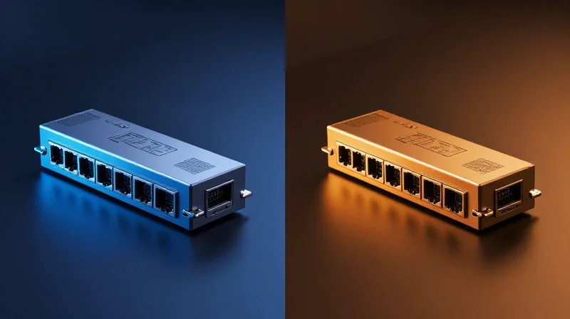
The fundamental difference between 100G ER4 and ZR4 optical modules centers on their optical power budget and amplification architecture: while ER4 relies on high-sensitivity Avalanche Photodiodes (APD) to reach 40km, ZR4 integrates a Semiconductor Optical Amplifier (SOA) to double that distance to 80km. This leap in performance necessitates significant trade-offs in power consumption, thermal management, and cost, making each module suitable for specific tiers of regional and metro-core connectivity.
Technical Specification Comparison
| Feature | 100G ER4 (40km) | 100G ZR4 (80km) |
|---|---|---|
| Max Transmission Distance | 40 km (Standard SMF) | 80 km (Standard SMF) |
| Optical Receiver Type | APD (Avalanche Photodiode) | SOA + PIN or SOA + APD |
| Typical Link Budget | 18 dB - 22 dB | 27 dB - 31 dB |
| Power Consumption | Approx. 3.5W - 4.5W | Approx. 5.5W - 6.5W |
| Laser Technology | 4x25G LAN-WDM EML | 4x25G LAN-WDM EML |
| Dispersion Limit | Lower (Up to 40km) | High (Requires SOA compensation) |
Amplification and Power Consumption
The integration of the Semiconductor Optical Amplifier (SOA) is the defining hardware divergence for ZR4. The SOA acts as a pre-amplifier before the signal reaches the photodiode, allowing the module to detect significantly weaker signals (lower BER thresholds) than a standalone APD. However, operating an internal amplifier increases the power draw. While a standard ER4 module typically operates within a 4.5W envelope, ZR4 modules often exceed 6W, requiring more robust cooling and advanced thermal dissipation within the network switch or router port.
Dispersion and Signal Integrity
At 80km, chromatic dispersion (CD) becomes a critical bottleneck for 100G signals. 100G ZR4 modules must be engineered with tighter tolerance for dispersion than ER4. While ER4 effectively ignores CD over 40km of G.652 fiber, ZR4 modules utilize the gain provided by the SOA to overcome the attenuation, but the system must still manage the pulse broadening associated with the longer fiber span. This is why ZR4 is often the limit for direct-detection (NRZ) technology before a transition to Coherent optics (like 100G/200G ZR) becomes necessary.
Common Deployment Questions
- Can I use a ZR4 module for a 40km link?
Technically yes, but it is not recommended without optical attenuators. Because the ZR4 has an integrated SOA, the incoming signal at 40km may be too strong, potentially saturating or damaging the receiver. - Is ZR4 more expensive than ER4?
Yes, ZR4 modules generally command a higher price point due to the added complexity of the internal Semiconductor Optical Amplifier and the higher-performance EML lasers required to maintain signal integrity over 80km. - Which module is better for data center interconnects (DCI)?
ER4 is preferred for campus-level DCI under 40km due to lower power and cost. ZR4 is the industry standard for regional DCI where spans exceed 40km but do not justify the cost of Coherent DWDM optics.
Power Consumption and Thermal Management
The Thermal Challenges of Ultra-Long Reach Modules
Ultra-long reach modules like the 100G ER4 and ZR4 consume significantly more power than standard LR4 modules due to the inclusion of active optical components required for long-distance signal integrity. While a standard 100G LR4 might operate comfortably around 3.5W, the integration of Semiconductor Optical Amplifiers (SOA) and sensitive Thermo-Electric Coolers (TEC) to stabilize laser wavelengths pushes the power envelope of the QSFP28 form factor to its limits, often reaching 5.5W to 6.5W.
Power Consumption Comparison by Module Type
| Module Type | Typical Power Consumption | Max Power Class | Key Thermal Component |
|---|---|---|---|
| 100G LR4 (10km) | 3.5W | Class 3 | Passive / Standard TOSA |
| 100G ER4 (40km) | 4.5W - 5.0W | Class 4 | TEC Cooling |
| 100G ZR4 (80km) | 5.5W - 6.5W | Class 5/7 | SOA + TEC Cooling |
Optimizing Heat Dissipation in High-Density Ports
In high-density switching environments, such as a 32-port 100G leaf switch, deploying multiple ZR4 modules in adjacent ports can create localized thermal 'hot spots.' Because these modules operate at higher temperatures, they can trigger thermal throttling, which reduces the bias current to the lasers and significantly degrades the bit error rate (BER). Network architects must ensure that the switch chassis supports 'Class 7' power levels and provides sufficient cubic feet per minute (CFM) of airflow to keep the internal case temperature below the typical 70°C threshold.
Deployment Best Practices
- Port Checker-boarding
Where possible, space ZR4/ER4 modules with empty ports or lower-power SR4/LR4 modules in between to prevent heat accumulation. - Airflow Direction
Verify that the module's operating temperature range matches the switch's airflow direction (Port-side Intake vs. Port-side Exhaust). - Real-time Monitoring
Utilize Digital Optical Monitoring (DOM) to track internal module temperature and SOA bias current in real-time to preemptive failure.
Thermal Management FAQ
- Will a 100G ZR4 work in any QSFP28 port?
Not necessarily. The port must be rated for at least Power Class 4 (up to 5W) or Class 7 (up to 7W). Some older 100G switches only support up to 3.5W per port. - How does heat affect the SOA in a ZR4 module?
Excessive heat increases the noise floor of the Semiconductor Optical Amplifier (SOA), which decreases the Optical Signal-to-Noise Ratio (OSNR) and can cause link flapping or total signal loss. - Is industrial temperature (I-Temp) support common for ZR4?
No. Due to the extreme power density and cooling requirements of the SOA, most 100G ZR4 modules are only rated for Commercial Temperature (0°C to 70°C).
Deployment Use Cases: From Metro DCI to ISP Backhauls

Optimizing Network Reach: Real-World Scenarios
The deployment of 100G ER4 and ZR4 optics is driven by the need for high-bandwidth connectivity over distances that exceed the 10km limit of standard LR4 modules without the overhead of external amplification. By utilizing the 1310nm and 1550nm bands respectively, these modules allow network architects to extend their 100G reach up to 80km or even 100km with host-side Forward Error Correction (FEC). This capability is critical for environments where installing mid-span repeaters or active optical transport systems is geographically or financially unfeasible.
Metro Data Center Interconnect (DCI)
In metro-scale DCI, 100G ER4 modules provide a seamless point-to-point link between primary data centers and disaster recovery sites. Because ER4 uses a cooled SOA (Semiconductor Optical Amplifier) or APD (Avalanche Photodiode), it can handle the higher insertion loss often found in aging metro fiber patches. ZR4 takes this further, allowing for connectivity between data centers in different cities within a single metropolitan region, providing the necessary link budget to overcome patch panel losses and fiber splices over a 60-80km span.
ISP Core and Edge Backhaul
Internet Service Providers (ISPs) utilize 100G ZR4 optics for backhauling traffic from remote access nodes to the centralized core. This is particularly common in suburban or rural deployments where the fiber run between a Point of Presence (POP) and the central office exceeds 40km. By using ZR4, ISPs avoid the high operational costs (OPEX) associated with maintaining active power and cooling for mid-span optical amplifiers in remote locations.
| Use Case | Optimal Module | Typical Distance | Primary Driver |
|---|---|---|---|
| Metro DCI | 100G ER4 | 25-40km | Low latency, simple point-to-point |
| Regional ISP Backhaul | 100G ZR4 | 60-80km | Elimination of mid-span amplification |
| Enterprise Campus | 100G ER4 | 15-30km | High-density interconnect across large sites |
| Rural Connectivity | 100G ZR4/ZR4+ (FEC) | 80km-100km | Cost-effective long-haul transport |
Enterprise and Campus Backbone
Large-scale industrial complexes, universities, and government research facilities often manage private fiber networks spanning dozens of miles. For these organizations, 100G ER4 provides the most stable upgrade path from 10G or 40G infrastructure. It allows for the reuse of existing single-mode fiber (SMF) plants while ensuring the signal integrity required for high-security, low-jitter applications like scientific data replication or high-frequency trading.
- Can 100G ZR4 reach 100km?
Yes, while the standard rating is 80km, using high-quality G.652 fiber and enabling KR4 FEC on the host equipment can extend the reach to approximately 100km depending on fiber loss. - Do ER4 and ZR4 require special fiber?
No, both are designed to work over standard G.652 Single-Mode Fiber (SMF), though ZR4 is more sensitive to chromatic dispersion at its 1550nm wavelength. - Are these modules compatible with passive DWDM?
Generally, ER4 and ZR4 use specific fixed wavelengths (LAN-WDM or 1550nm) and are intended for point-to-point links rather than being multiplexed into standard DWDM grids.
Interoperability and Compatibility Challenges
Interoperability and Compatibility Challenges
Interoperability for 100G ultra-long-reach modules is not guaranteed by the form factor alone. While the QSFP28 interface is standardized, the underlying optical specifications and the digital signal processing requirements—specifically Forward Error Correction (FEC)—vary significantly between ER4 and ZR4 variants. Ensuring a stable link between a Cisco switch and a Juniper or Arista router using these modules requires deep technical validation of the host port's power capabilities and the synchronization of error-correction algorithms.
The FEC Misalignment Dilemma
The most common cause of link failure in 100G long-haul deployments is FEC mismatch. Standard 100G ER4 (40km) modules typically follow the IEEE 802.3ba standard, which does not mandate host-side FEC for the optical link to function. However, many 100G ER4-Lite or 100G ZR4 modules rely on KR4 FEC (defined in IEEE 802.3bj) to reach their maximum rated distances. If one end of the link has FEC enabled and the other disabled, or if the host switch cannot support the specific FEC type required by the module's internal chipset, the link will either fail to come up or suffer from excessive bit error rates (BER).
| Feature | Standard 100G ER4 | 100G ER4-Lite / ZR4 |
|---|---|---|
| IEEE Standard | 802.3ba | Non-Standard / MSA |
| Host FEC Requirement | Optional / Not Required | Mandatory (usually KR4 FEC) |
| Wavelength Grid | LAN-WDM (1295-1309nm) | LAN-WDM (1295-1309nm) |
| Power Dissipation | Typically < 3.5W | Often 4.5W to 6W |
Host Platform Power and Thermal Constraints
Ultra-long-reach modules like the ZR4 integrate more complex APD receivers and high-power SOAs (Semiconductor Optical Amplifiers), which push the power consumption of the QSFP28 package to its limits. Traditional QSFP28 ports are often rated for Power Class 4 (up to 3.5W). However, high-performance ZR4 modules frequently operate in Power Class 6 or 7 (up to 5W or 6W). Inserting a ZR4 module into a legacy or high-density line card that cannot provide sufficient current or adequate airflow for cooling will lead to thermal throttling or permanent hardware damage.
- Can I connect a 100G ER4 to a 100G ZR4?
Generally, no. While they share the same wavelength grid, the ZR4 has a significantly higher launch power and receiver sensitivity. Connecting them directly without heavy attenuation will likely saturate or damage the ER4 receiver. - How do I fix a 'Link Down' status with ZR4 modules?
Check the FEC settings on the host switch. Ensure that 'encoding fec rs' or equivalent commands are enabled on both sides, and verify that the switch port supports the module's power class. - Does fiber type affect interoperability?
Yes. While both use G.652 SMF, using G.655 (NZDSF) fiber can cause higher-than-expected chromatic dispersion for these LAN-WDM wavelengths, leading to compatibility issues regardless of the module brand.
Calculating Your Link Budget for 80km Spans
Calculating a link budget for 80km spans is the fundamental bridge between theoretical specifications and real-world performance, ensuring that the optical power reaching the receiver is strong enough to maintain a low Bit Error Rate (BER) despite the significant attenuation of long-distance fiber. For 100G connectivity, this process involves more than just subtracting distance from power; it requires a granular accounting of connector loss, splice degradation, and the specific sensitivity thresholds of APD-based receivers used in ER4 and ZR4 modules.
The Link Budget Equation for 100G Ultra-Long Reach
The core formula for a 100G link budget is: Total Link Loss (dB) = (Fiber Length × Attenuation Coefficient) + (Number of Connectors × Connector Loss) + (Number of Splices × Splice Loss) + Safety Margin. Once this total is calculated, it must be compared against the transceiver's Power Budget (Minimum Launch Power - Receiver Sensitivity). For an 80km span using ZR4, the target loss budget is typically around 25-28 dB, depending on the manufacturer's specs.
| Component | Typical Loss Value | 80km Span Estimate |
|---|---|---|
| Fiber Attenuation (1550nm) | 0.22 dB/km | 17.6 dB |
| Fiber Attenuation (1310nm) | 0.35 dB/km | 28.0 dB |
| Connector Pair Loss | 0.50 dB per pair | 1.0 dB (2 pairs) |
| Fusion Splice Loss | 0.10 dB per splice | 0.8 dB (8 splices) |
| System Safety Margin | 2.0 - 3.0 dB | 3.0 dB |
Critical Factors Beyond Simple Attenuation
- Chromatic Dispersion (CD) Penalty
At 80km, 1550nm signals (ZR4) experience significant pulse spreading. The receiver must have a dispersion tolerance high enough to compensate, or the 'effective' sensitivity will drop, necessitating a higher power margin. - FEC (Forward Error Correction) Impact
Most 100G ZR4 modules require Host-FEC (RS-FEC) to achieve 80km. FEC improves the coding gain, effectively lowering the required OSNR, but the link budget calculation must use the 'Post-FEC' sensitivity values for accuracy. - Optical Return Loss (ORL)
High-power long-reach lasers are sensitive to back-reflections. Ensuring all connectors are APC (Angled Physical Contact) and clean is vital to preventing laser instability that can shrink your power budget.
Practical Link Budget FAQ
- Can 100G ER4 reach 80km?
Standard 100G ER4 is rated for 40km. To reach 80km, you must use ER4 Lite with an SOA (Semiconductor Optical Amplifier) or transition to ZR4, which is natively designed for 80km budgets. - Why is a 3dB safety margin recommended?
Fiber performance degrades over time due to environmental factors, and future maintenance (like emergency fiber repairs) will introduce new splices that add unplanned loss. - How does wavelength choice affect the budget?
ZR4 uses the 1550nm C-band because it has the lowest attenuation (approx. 0.22dB/km), whereas ER4 uses the 1310nm O-band (approx. 0.35dB/km), making 80km nearly impossible for ER4 without massive amplification.
Understanding the nuances of 100G ER4 and ZR4 is essential for building a scalable, cost-effective long-haul network. Whether you are upgrading a metro ring or connecting data centers, selecting the right ultra-long-haul module ensures peak performance. Contact our technical specialists today for a detailed link analysis and customized hardware recommendations.