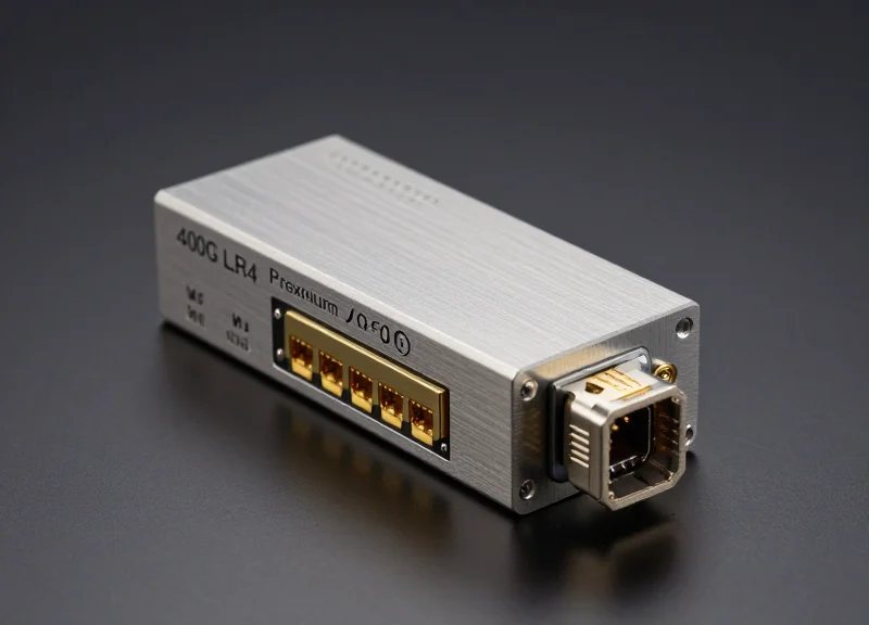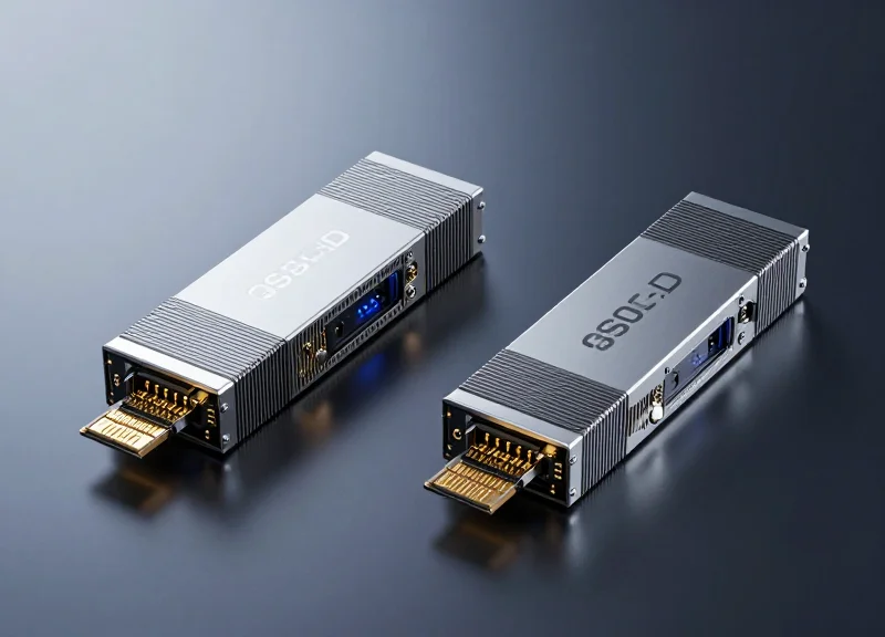
As data centers transition to 800G to meet the demands of AI/ML and hyperscale computing, selecting the right optical interface is no longer just about speed—it is about balancing power, latency, and cost. This guide breaks down the 800G QSFP-DD SR8 against its primary competitors to help you architect a future-proof network.
The Rise of 800G: Why the QSFP-DD SR8 is a Market Leader

The 800G QSFP-DD SR8 is a market leader because it represents the most mature and cost-effective path for scaling data center bandwidth to 800Gbps using established 100G PAM4 per-lane signaling. By utilizing eight lanes of 100G, the SR8 interface allows network operators to double the density of standard 400G ports without increasing the physical footprint, making it the preferred choice for high-radix switches in AI clusters and hyperscale cloud environments. Its dominance is further cemented by its backward compatibility with legacy QSFP form factors, providing a low-risk migration path for infrastructure upgrades.
The Technological Drivers Behind 800G Dominance
The rapid ascent of 800G technology is primarily fueled by the exponential growth in traffic from Artificial Intelligence (AI) and Machine Learning (ML) workloads. These applications require massive throughput and ultra-low latency, pushing the limits of traditional 400G infrastructure. The QSFP-DD (Quad Small Form-factor Pluggable Double Density) multisource agreement (MSA) has evolved to meet these needs, providing a thermal management profile and electrical interface capable of supporting 800G while maintaining backward compatibility with legacy QSFP modules. This ensures that the same switch hardware can support a mix of legacy and next-generation optics.
Key Performance Metrics of the SR8 Interface
| Feature | QSFP-DD SR8 Specification |
|---|---|
| Data Rate | 800Gbps (8 x 106.25Gbps) |
| Modulation | PAM4 |
| Reach | Up to 60m (OM3) or 100m (OM4/OM5) MMF |
| Connector Type | MPO-16 or Dual MPO-12 |
| Power Consumption | Typically <16W |
Strategic Advantages and Market Positioning
- Why is the SR8 preferred over 2x400G breakout solutions?
The SR8 offers a native 800G interface that simplifies cabling and management in leaf-spine architectures, reducing the total number of optical components compared to managing multiple discrete 400G links. - How does the QSFP-DD form factor compare to OSFP for 800G?
While OSFP offers superior thermal performance for higher wattages, QSFP-DD is favored for its density and backward compatibility with QSFP28 and QSFP56 ports, allowing for a more flexible and cost-effective phased upgrade path. - What role does PAM4 signaling play in its success?
100G PAM4 signaling is the industry standard for high-speed optics, ensuring broad interoperability between different switch silicon vendors and transceiver manufacturers, which lowers the barrier to entry for 800G adoption.
In summary, the QSFP-DD SR8 occupies a 'sweet spot' in the market. It provides the necessary bandwidth for the next generation of high-density switching while leveraging existing multi-mode fiber (MMF) infrastructure and 100G-per-lane technology. As data centers shift toward 51.2T and 102.4T switching capacities, the SR8 stands as the most reliable short-reach solution for interconnecting racks at scale.
Technical Architecture: Decoding the 800G QSFP-DD SR8
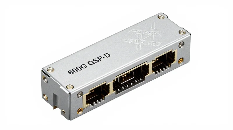
Technical Architecture: Decoding the 800G QSFP-DD SR8
The 800G QSFP-DD SR8 represents the pinnacle of short-reach optical interconnects, achieving a massive 800 Gbps throughput by leveraging eight parallel lanes of 100 Gbps PAM4 (4-level Pulse Amplitude Modulation). Unlike traditional NRZ signaling, PAM4 doubles the data rate within the same bandwidth by encoding two bits per symbol, a transition essential for meeting the high-density requirements of modern spine-leaf architectures. This 8-lane parallel design ensures low latency by avoiding complex multiplexing schemes, making it the preferred choice for high-frequency trading and AI training clusters.
The PAM4 Modulation Engine
At the heart of the SR8 module is the 8x100G electrical-to-optical conversion process. The module interfaces with the host via an 8-lane electrical bus (800GAUI-8) following the IEEE 802.3ck standard. On the optical side, eight VCSEL (Vertical-Cavity Surface-Emitting Laser) arrays operate at 850nm, each carrying 100 Gbps. This parallel approach requires Multi-Mode Fiber (MMF) cabling, specifically OM3 or OM4, to manage the signal across eight distinct fiber pairs.
Connectivity and Physical Layer Specs
To accommodate the 16 fibers required for 8-channel transmit and receive paths, the QSFP-DD SR8 utilizes the MPO-16 (Multi-fiber Push-On) connector. This high-density connector is key to maintaining the form factor of the QSFP-DD, which provides an additional row of electrical pins to support the 8-lane interface while remaining backwards compatible with previous QSFP generations.
| Parameter | Specification |
|---|---|
| Modulation Type | PAM4 (8 Lanes) |
| Wavelength | 850 nm |
| Maximum Reach | 60m (OM3) / 100m (OM4/OM5) |
| Connector Interface | MPO-16/APC or MPO-16/PC |
| Power Consumption | Typically <14W |
| Standard Compliance | IEEE 802.3ck / QSFP-DD MSA |
Architecture FAQ
- Why does the SR8 use 8 lanes instead of 4?
Utilizing 8 lanes allows the use of mature 100G-per-lane components, which are more cost-effective and yield higher production stability compared to the emerging 200G-per-lane technology. - Can the SR8 be used with Single-Mode Fiber?
No, the SR8 is specifically designed for Multi-Mode Fiber (MMF) using VCSEL technology. For single-mode applications, standards like 800G DR8 are required. - What is the role of the DSP in this architecture?
The Digital Signal Processor (DSP) handles clock and data recovery (CDR) and compensates for signal degradation caused by chromatic dispersion over the fiber.
The Contenders: SR8 vs. DR8 and 2xFR4 Alternatives
The Contenders: SR8 vs. DR8 and 2xFR4 Alternatives
Choosing between 800G SR8 and its alternatives depends primarily on the data center's existing fiber plant and the required link distance, as SR8 serves short-reach multimode needs while DR8 and 2xFR4 target single-mode scalability. While the SR8 remains the benchmark for cost-effective short-reach applications within the rack, single-mode alternatives are essential for campus-wide connectivity or high-density spine-leaf layers where 100-meter limits are insufficient.
800G DR8: Scaling Beyond the Rack
The 800G DR8 module is designed for 500-meter reaches over single-mode fiber (SMF), utilizing 8 parallel channels of 100G PAM4. Like the SR8, it often employs an MPO-16 connector, making it a logical transition for operators moving from multimode to single-mode without changing their parallel cabling philosophy. Its primary advantage is its ability to support breakout configurations (e.g., 1x800G to 2x400G or 8x100G) over distances that exceed the physical limitations of OM4 fiber.
800G 2xFR4: Maximizing Fiber Density
Unlike the parallel architectures of SR8 and DR8, the 2xFR4 alternative uses Coarse Wavelength Division Multiplexing (CWDM) to combine four 100G channels onto a single fiber pair. By providing two 400G interfaces in a single 800G QSFP-DD housing, it achieves a 2km reach over duplex SMF. This significantly reduces the total amount of fiber required compared to parallel optics, though it involves higher module complexity and different connector types like CS or Dual LC.
| Feature | 800G SR8 | 800G DR8 | 800G 2xFR4 |
|---|---|---|---|
| Reach | 60m (OM3) / 100m (OM4) | 500m | 2km |
| Fiber Type | Multimode (MMF) | Single-mode (SMF) | Single-mode (SMF) |
| Connector | MPO-16 | MPO-16 / MPO-12 | Dual LC / CS |
| Modulation | 8x100G PAM4 | 8x100G PAM4 | 2x(4x100G CWDM) |
| Fiber Count | 16 Fibers | 16 or 12 Fibers | 4 Fibers (2 Pairs) |
Selection Criteria and Operational Impact
- When should I choose DR8 over SR8?
DR8 is the preferred choice when link distances exceed 100 meters or when a unified single-mode fiber plant is required for future scalability to 1.6T and beyond. - Is 2xFR4 more cost-effective than SR8?
In terms of transceiver unit cost, no; however, 2xFR4 significantly reduces 'day two' costs by requiring fewer fiber strands to carry the same data volume over longer distances. - Are SR8 and DR8 transceivers interoperable?
No. They operate on different wavelengths (850nm for SR8 vs 1310nm for DR8) and utilize different fiber types, making direct optical connection impossible.
Latency Benchmarks: Impact on AI/ML Workloads

In the context of 800G networking, latency is not merely a function of light speed through fiber but is increasingly dominated by Digital Signal Processing (DSP) and Forward Error Correction (FEC) algorithms required to maintain signal integrity over 112G SerDes lanes. For AI/ML workloads, specifically those utilizing RDMA over Converged Ethernet (RoCE) or InfiniBand, the 800G QSFP-DD SR8 offers a latency advantage in short-reach scenarios by minimizing the complexity of optical-to-electrical conversions compared to long-reach coherent alternatives.
The DSP and FEC Latency Trade-off
At 800G speeds, the transition to 100G per-lane PAM4 modulation necessitates aggressive FEC to manage the Bit Error Rate (BER). The latency introduced by these components typically falls into two categories: the fixed latency of the DSP silicon and the variable latency of the FEC logic. While SR8 (multimode) and DR8 (single-mode) both utilize similar 112G SerDes, the internal architecture of the modules can differ in how they handle clock and data recovery (CDR), impacting the nanosecond-scale performance critical for synchronous GPU training tasks.
| Metric | 800G SR8 (Multimode) | 800G DR8 (Single-mode) | 800G 2xFR4 (CWDM) |
|---|---|---|---|
| Typical DSP Latency | ~100-150 ns | ~100-150 ns | ~150-200 ns |
| FEC Requirement | KP4 FEC | KP4 FEC | KP4 + Intensive DSP |
| Propagation Delay | ~5 ns/m | ~5 ns/m | ~5 ns/m |
| Workload Suitability | Intra-rack GPU Fabric | Leaf-to-Spine | Inter-pod / DCI |
Impact on Distributed Training Workloads
AI training involves frequent 'All-Reduce' operations where GPUs must synchronize gradients across the entire fabric. In a cluster of thousands of GPUs, a 50ns difference in module latency can compound across multiple switch hops, leading to significant 'tail latency' that stalls the computation pipeline. The 800G SR8 is often preferred for the 'front-end' and 'back-end' networks within a single row of racks because its parallel 8-channel design avoids the additional multiplexing/demultiplexing (MUX/DEMUX) delays found in WDM-based alternatives like 2xFR4.
LPO: The Future of Ultra-Low Latency
Linear Drive Pluggable Optics (LPO) is an emerging alternative to traditional SR8 and DR8 modules. By removing the DSP entirely and relying on the host ASIC for signal integrity, LPO can reduce latency to sub-10ns levels. However, this requires high-performance host platforms and limits the reach compared to standard QSFP-DD SR8 modules.
Latency FAQ for AI Networking
- Does fiber type affect 800G latency?
The propagation delay of light is nearly identical in multimode (SR8) and single-mode (DR8) fiber. The primary latency difference comes from the transceiver electronics and the signal processing required to drive the specific media. - Why is SR8 considered the benchmark for low-latency AI pods?
SR8 uses a direct 8-channel parallel mapping that aligns perfectly with 8-lane GPU architectures, minimizing the need for complex gearboxing or re-timing that can add nanoseconds to the data path. - How does FEC impact 800G performance?
FEC is mandatory for 800G PAM4 to ensure reliability. While it adds a small constant latency (approx. 100ns), it prevents packet drops that would cause massive multi-millisecond retransmission delays in AI training.
Power Consumption Analysis: Watts per Gigabit
The 800G QSFP-DD SR8 module stands as the most power-efficient choice in the 800G ecosystem, typically consuming between 14W and 16W, which translates to a highly optimized efficiency of approximately 0.0175 to 0.02 Watts per Gigabit. This efficiency is primarily driven by the use of Vertical-Cavity Surface-Emitting Lasers (VCSELs), which require significantly lower drive currents and thermal stabilization compared to the Externally Modulated Lasers (EML) or Silicon Photonics (SiPh) used in single-mode alternatives like DR8 or 2xFR4.
Thermal Profiles: SR8 vs. Single-Mode Contenders
In high-density AI clusters, the cumulative thermal load of 32 or 64 ports of 800G can exceed the cooling capacity of standard air-cooled chassis. While the SR8 remains near the 14W floor, single-mode modules such as the 800G DR8 or 2xFR4 often push toward 18W or higher to maintain signal integrity over longer reaches. This 2W to 4W delta per module may seem negligible in isolation, but across a 51.2T switch, it represents an additional 250W of heat that must be dissipated, impacting both cooling costs and the reliability of the switch silicon.
| Module Type | Typical Power (W) | Max Power (W) | Efficiency (W/Gbps) |
|---|---|---|---|
| 800G QSFP-DD SR8 | 14.2W | 16.0W | 0.0178 |
| 800G QSFP-DD DR8 | 16.5W | 18.5W | 0.0206 |
| 800G QSFP-DD 2xFR4 | 17.8W | 20.0W | 0.0223 |
| 800G OSFP SR8 | 14.0W | 15.5W | 0.0175 |
The Impact of DSP Integration
The 7nm and 5nm Digital Signal Processors (DSP) inside these modules are the largest contributors to the power envelope. Because SR8 modules operate over shorter multimode fiber distances, the DSP equalization requirements are slightly less aggressive than those needed for the complex chromatic dispersion compensation in single-mode optics. Furthermore, as the industry moves toward Linear Drive (LPO) solutions, the SR8 architecture is better positioned to eliminate the DSP entirely, potentially dropping power consumption below 10W per module.
Power & Efficiency FAQ
- Why does the SR8 consume less power than the DR8?
SR8 uses VCSEL technology which is inherently lower power than the EML or SiPh lasers required for single-mode transmission. Additionally, the shorter reach of SR8 reduces the power needed for signal amplification. - How does power consumption affect TCO in AI data centers?
Higher power consumption increases direct electricity costs and demands more expensive cooling infrastructure. For every 1W saved at the transceiver level, data centers often save an additional 0.5W to 1.0W in cooling overhead. - Is there a power difference between QSFP-DD and OSFP form factors?
While the internal optics are similar, OSFP modules often have better thermal dissipation due to integrated heat sinks, which can allow the DSP to run slightly more efficiently, though the raw power draw remains comparable.
Total Cost of Ownership (TCO): CAPEX vs. OPEX
Total Cost of Ownership (TCO): CAPEX vs. OPEX
Determining the TCO for 800G deployments requires a balance between the lower initial Capital Expenditure (CAPEX) of VCSEL-based multimode optics and the long-term Operational Expenditure (OPEX) benefits of single-mode infrastructure. While the 800G QSFP-DD SR8 is the most budget-friendly transceiver for short-reach AI clusters, the requirement for high-density MPO-16 OM4/OM5 cabling can diminish these savings when compared to the cheaper, more scalable OS2 fiber used by DR8 and 2xFR4 alternatives.
CAPEX: Hardware and Infrastructure Investment
In a greenfield data center deployment, the CAPEX is split between the active transceivers and the passive cable plant. The SR8 module utilizes Vertical-Cavity Surface-Emitting Lasers (VCSELs), which are significantly less expensive to produce than the Silicon Photonics (SiPh) or Electro-absorption Modulated Lasers (EML) found in DR8 or 2xFR4 modules.
| Component | 800G SR8 (MMF) | 800G DR8 (SMF) | 800G 2xFR4 (SMF) |
|---|---|---|---|
| Transceiver Cost | Baseline (1.0x) | ~1.4x - 1.6x | ~1.8x - 2.2x |
| Cabling Media | OM4/OM5 (Expensive) | OS2 (Inexpensive) | OS2 (Inexpensive) |
| Connector Type | MPO-16 | MPO-12 | Dual LC |
| Installation Labor | High (Polarity management) | Moderate | Low |
OPEX: Power Consumption and Thermal Management
Operational costs at 800G are heavily influenced by the power envelope of each module. Higher power consumption not only increases the electricity bill but also necessitates more robust (and expensive) cooling solutions within the rack. SR8 modules generally operate at lower power levels due to the simpler laser architecture.
| OPEX Metric | 800G SR8 | 800G DR8 | 800G 2xFR4 |
|---|---|---|---|
| Power Draw (Typical) | 12W - 14W | 15W - 16W | 16W - 18W |
| Cooling Overhead | Low | Medium | High |
| Energy Cost (3yr/port) | Lowest | Moderate | Highest |
Financial Strategy and FAQ
- When is the SR8 the most cost-effective choice?
SR8 is most economical for high-density, short-reach (under 50m) Top-of-Rack to Leaf switch connections where the quantity of transceivers is high and the distance does not necessitate single-mode optics. - Does single-mode fiber (SMF) offer better long-term ROI?
Yes. While DR8 transceivers are pricier, the OS2 fiber infrastructure supports future upgrades to 1.6T and 3.2T without replacing the cabling, whereas MMF infrastructure often requires a total overhaul for next-gen speeds. - How does power consumption affect the TCO?
In a 100,000-node AI cluster, a 2-watt difference per module (SR8 vs. DR8) can result in millions of dollars in saved energy and cooling costs over a three-year lifecycle.
Form Factor Battle: QSFP-DD vs. OSFP
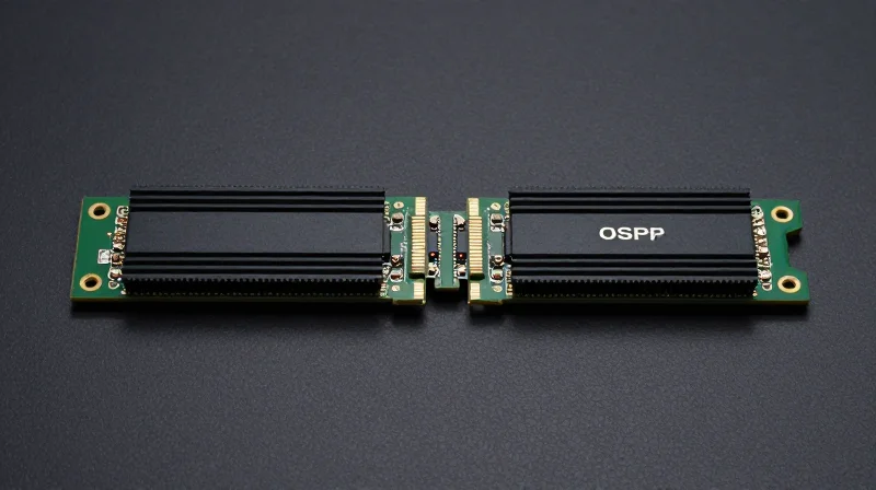
Form Factor Battle: QSFP-DD vs. OSFP
The competition between QSFP-DD and OSFP at the 800G level represents a strategic choice between legacy compatibility and thermal headroom. While QSFP-DD offers seamless integration with existing QSFP-based infrastructure, OSFP provides a larger physical footprint and superior integrated cooling capabilities, making it better suited for the high-wattage demands of next-generation AI and high-performance computing (HPC) clusters.
Thermal Management and Heat Dissipation
As 800G SR8 modules push power consumption levels toward 12W-16W, heat dissipation becomes the primary engineering hurdle. OSFP (Octal Small Form-factor Pluggable) modules feature an integrated heat sink, which allows for significantly more efficient airflow and thermal transfer directly from the module. QSFP-DD (Double Density), by contrast, relies on the equipment's cage and external heat sinks. While QSFP-DD has evolved to handle 800G, OSFP's design is inherently more robust for future-proofing thermal envelopes as data rates climb toward 1.6T.
| Feature | QSFP-DD (800G) | OSFP (800G) |
|---|---|---|
| Dimensions (Width) | 18.35 mm | 22.58 mm |
| Backward Compatibility | High (Supports QSFP28/56) | Requires Adapter |
| Heat Dissipation | External Heat Sink (Cage) | Integrated Heat Sink |
| Max Power Envelope | Approx. 14W - 15W | 15W - 18W+ |
| Port Density | 36 ports per 1U | 32-36 ports per 1U |
Backward Compatibility and Integration Strategy
For many operators, the decision hinges on existing port density and the cost of transition. QSFP-DD SR8 modules are physically compatible with previous QSFP slots, allowing data centers to maintain a uniform hardware lifecycle. OSFP requires a larger port and, while adapters exist to house QSFP modules in OSFP cages, the reverse is not possible. This makes QSFP-DD the preferred choice for enterprise upgrades, while OSFP is increasingly dominant in 'greenfield' hyperscale AI builds where maximum cooling efficiency is prioritized over legacy support.
- Can OSFP modules fit into QSFP-DD ports?
No, OSFP modules are physically wider and deeper than QSFP-DD modules, making them mechanically incompatible with QSFP-DD cages. - Which form factor is more reliable for 800G SR8?
Both are reliable, but OSFP generally runs cooler in high-density configurations, which can lead to longer component lifespan in extreme thermal environments. - Does 800G SR8 require different cabling for these form factors?
No, the optical interface for SR8 (MPO-16 or dual MPO-12) remains the same regardless of whether the module is QSFP-DD or OSFP.
Deployment Strategies: When to Choose SR8
Optimal Deployment Scenarios for 800G SR8
The decision to deploy 800G QSFP-DD SR8 modules hinges on the physical architecture of the data center, specifically the distance between interconnect points and the existing fiber plant. SR8 is the most cost-effective solution for sub-100m links, making it the standard for Top-of-Rack (ToR) to Leaf switch connectivity. In environments where low latency and power-per-gigabit are critical performance indicators, the SR8's simpler VCSEL-based design outperforms more complex single-mode alternatives.
ToR-to-Leaf and Server Connectivity
In modern AI-driven clusters, high-bandwidth server-to-switch connectivity is paramount. The 800G SR8 module is frequently used in a breakout configuration (e.g., 2x400G or 8x100G) to connect high-performance NICs to ToR switches. This strategy maximizes port density on the switch side while maintaining a manageable power profile within the rack's thermal limits.
Leaf-Spine Architectures and Cabling Efficiency
For Leaf-Spine architectures where the distance between rows is kept under 100 meters using OM4 or OM5 multimode fiber, SR8 offers a significant reduction in transceiver costs. While single-mode fiber (SMF) is often touted for future-proofing, the current price premium for 800G DR8 or FR8 modules can be 50-100% higher than SR8. If the facility layout permits, sticking to MPO-16 multimode infrastructure allows for rapid scaling without the high entry cost of single-mode optics.
| Deployment Scenario | Recommended Module | Max Distance | Cabling Type |
|---|---|---|---|
| Intra-Rack (Server to ToR) | 800G SR8 (Breakout) | 30m - 50m | OM3/OM4 |
| Inter-Rack (ToR to Leaf) | 800G SR8 | 60m - 100m | OM4/OM5 |
| Row-to-Row (Leaf to Spine) | 800G SR8 / 2xDR4 | 100m / 500m | OM4 / SMF |
| Campus/Data Center Interconnect | 800G FR8 / LR8 | 2km - 10km | Single-Mode (SMF) |
Strategic Decision Checklist
- Is your link distance under 100 meters?
If yes, SR8 is the primary candidate to minimize CAPEX and power consumption. - Is power density a constraint in your racks?
SR8 modules typically consume less power (approx. 12-14W) compared to single-mode modules (16W+), making them easier to cool in high-density 800G environments. - Do you require backward compatibility?
QSFP-DD SR8 modules provide better backward compatibility options for 400G and 100G legacy systems using standard MPO-16/MPO-12 cabling. - What is the budget for optical infrastructure?
Choose SR8 when the total cost of ownership (transceiver + cable) must be minimized for large-scale deployments within a single data hall.
Future-Proofing Your Infrastructure for 1.6T

Future-Proofing Your Infrastructure for 1.6T
Future-proofing an 800G deployment requires a technical alignment between current physical layer choices and the upcoming 224G-per-lane signaling standards that will define 1.6T networking. For most operators, the decision to deploy 800G QSFP-DD SR8 or OSFP modules is not just about immediate performance but about establishing a hardware foundation that can support the next cycle of switch ASICs without requiring a massive overhaul of the cabling plant or thermal management systems.
The SerDes Evolution: From 112G to 224G
The transition from 800G to 1.6T is primarily driven by the evolution of SerDes (Serializer/Deserializer) technology. While current 800G modules utilize 112G SerDes across 8 lanes, 1.6T will necessitate 224G SerDes. This shift places immense pressure on the electrical interface and thermal efficiency. Organizations opting for OSFP form factors at 800G may find a smoother transition to 1.6T due to the OSFP's superior thermal dissipation capabilities and the 'OSFP1600' specification already being integrated into roadmap designs. Conversely, QSFP-DD must continue to evolve its heat sink and connector designs to handle the increased power density of 1.6T.
| Feature | 800G Standard (Current) | 1.6T Standard (Future) |
|---|---|---|
| Electrical Lane Speed | 112G PAM4 | 224G PAM4 |
| Number of Lanes | 8 Lanes | 8 Lanes |
| Preferred Form Factor | QSFP-DD / OSFP | OSFP / QSFP-112 |
| Estimated Power Draw | 14-18W | 22-28W |
| Cabling Compatibility | MPO-16 / Dual MPO-12 | MPO-16 (Optimized for 224G) |
Investment Protection and Connectivity Roadmap
To protect the investment in 800G, infrastructure leads should prioritize modularity in their fiber plant. While SR8 solutions provide the lowest cost today, they rely on Multimode Fiber (MMF) which has tighter reach constraints as speeds increase. Moving toward 1.6T, single-mode alternatives or advanced silicon photonics may become the baseline for the backbone, leaving SR8 as a top-of-rack solution only. Testing and validating high-quality MPO-16 cabling systems now can provide the necessary bandwidth headroom for both 800G SR8 today and 1.6T parallel optics tomorrow.
- Will 800G QSFP-DD modules work in 1.6T switch ports?
Backward compatibility depends on the switch silicon; however, most 1.6T OSFP ports are designed to support 800G OSFP modules through mechanical adapters or native port mapping, whereas QSFP-DD compatibility may require specific legacy support configurations. - When is 1.6T expected to become mainstream?
1.6T is expected to begin early sampling in late 2026 with broader data center adoption occurring between 2025 and 2026 as 51.2T and 102.4T switching silicon becomes available. - Is OSFP the definitive winner for the 1.6T era?
While OSFP currently has a thermal advantage, the development of QSFP-112 and enhanced cooling techniques for QSFP-DD suggest that the market will remain fragmented based on specific vendor ecosystem preferences.
Navigating the 800G landscape requires a deep understanding of your specific traffic patterns and physical constraints. While the QSFP-DD SR8 offers unparalleled cost-efficiency for short-reach applications, single-mode alternatives provide the distance needed for larger fabrics. Contact our technical engineering team today for a custom bill-of-materials (BOM) analysis to optimize your 800G deployment.