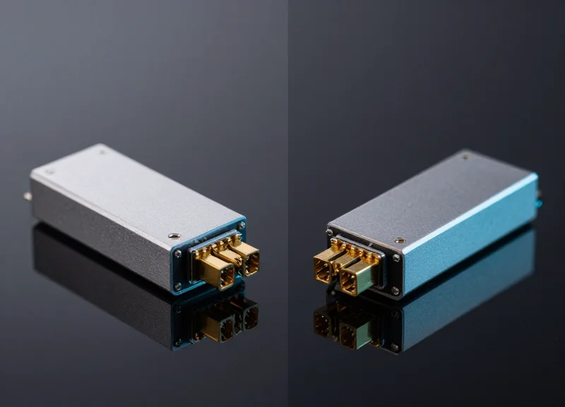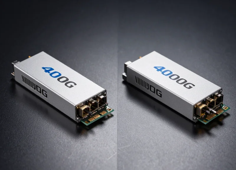
As data centers transition from 100G to 400G to meet AI and cloud demands, selecting the right optical standard becomes a high-stakes decision. While 400G FR4 is gaining massive traction, how does it truly stack up against alternatives like DR4, SR8, or LR4? This guide leverages twenty years of Silicon Valley engineering experience to break down the technical trade-offs and financial implications of your 400G interconnect strategy.
The Evolution of 400G: Why FR4 Matters Now

The 400G Shift: Meeting Hyperscale Demands
The migration from 100G to 400G is driven by the insatiable demand for bandwidth in cloud computing, AI workloads, and 5G backhaul. As data centers hit the limits of 100G density, 400G Ethernet provides a 4x increase in capacity per rack unit. Within this evolution, the 400G FR4 standard has emerged as a pivotal solution, leveraging Coarse Wavelength Division Multiplexing (CWDM) to transmit 400Gbps over just two single-mode fibers (SMF) for distances up to 2km. This shift is not just about speed; it is about maintaining economic viability while scaling fiber infrastructure.
Bridging the Gap Between Short and Long Reach
Early 400G deployments relied heavily on SR8 (short reach) for local links and DR4 for 500m spans. However, the FR4 standard (400GBASE-FR4) fills a critical void for mid-reach applications. By using four 100G PAM4 wavelengths, it avoids the high fiber counts required by parallel fiber solutions (like DR4 or SR8) while remaining significantly more affordable than long-range LR4 modules. It essentially serves as the 'Goldilocks' solution for spine-leaf architectures in hyperscale facilities.
| Standard | Max Reach | Fiber Count | Fiber Type | Wavelength Technology |
|---|---|---|---|---|
| 400G SR8 | 100m | 16 Fibers | Multimode (OM4) | 8x50G (850nm) |
| 400G DR4 | 500m | 8 Fibers | Single-mode | 4x100G (1310nm) |
| 400G FR4 | 2km | 2 Fibers | Single-mode | 4x100G (CWDM) |
| 400G LR4 | 10km | 2 Fibers | Single-mode | 4x100G (LAN-WDM) |
Key Drivers for FR4 Adoption
- Why choose FR4 over DR4 for 500m+ distances?
While DR4 is excellent for very short spans, it requires 8 fibers. FR4 uses wavelength multiplexing to run on a single duplex fiber pair, drastically reducing cabling complexity and operational costs for mid-range spans. - How does FR4 impact total cost of ownership (TCO)?
By minimizing fiber consumption and using less expensive CWDM optics compared to the high-precision lasers required for LR4, FR4 offers the optimal price-to-performance ratio for internal data center fabric. - Is FR4 compatible with existing 100G CWDM4 infrastructure?
Yes, FR4 was designed to follow the logic of 100G CWDM4, allowing operators to reuse existing single-mode duplex fiber plants, making it the most seamless upgrade path for 400G migration.
Technical Architecture: FR4 vs. DR4 vs. SR8

Technical Architecture: FR4 vs. DR4 vs. SR8
The fundamental difference between 400G FR4 and its alternatives lies in how the optical signal is organized: FR4 uses spectral efficiency to minimize fiber count, while DR4 and SR8 utilize physical parallelism. Choosing between these architectures requires balancing the complexity of the transceiver's internal optics against the cost and density of the data center's fiber cabling plant.
400G FR4: The CWDM4 Approach
The 400G FR4 module (specifically designed for 2km reaches) operates on single-mode fiber (SMF) using Coarse Wavelength Division Multiplexing (CWDM). It takes four electrical lanes of 100G PAM4 and converts them into four optical wavelengths: 1271nm, 1291nm, 1311nm, and 1331nm. These are multiplexed onto a single fiber for transmission and demultiplexed at the receiving end. This allows for a simple LC duplex connector interface, utilizing only two fiber strands for a complete 400G link.
400G DR4 and SR8: Parallel Optics
Conversely, 400G DR4 and SR8 avoid the complexity of multiplexing different wavelengths. 400G DR4 uses four parallel lanes of 100G PAM4 on the same 1310nm wavelength across four separate fiber pairs (8 fibers total). 400G SR8 targets short-reach multi-mode fiber (MMF), traditionally using eight lanes of 50G PAM4 across 16 fiber strands. These parallel architectures require MPO/MTP connectors, which increase the complexity of cable management and the physical footprint of the patch panels.
| Feature | 400G FR4 | 400G DR4 | 400G SR8 |
|---|---|---|---|
| Fiber Type | Single-mode (SMF) | Single-mode (SMF) | Multi-mode (MMF) |
| Max Reach | 2km | 500m | 70m (OM3) / 100m (OM4) |
| Connector | LC Duplex | MPO-12 | MPO-16 / MPO-24 |
| Wavelengths | 4 (CWDM4) | 1 (1310nm) | 1 (850nm) |
| Fiber Count | 2 Fibers | 8 Fibers | 16 Fibers |
Architectural Nuances & FAQ
- Why is FR4 considered more scalable for long distances?
Because FR4 uses CWDM to consolidate four signals onto a single fiber pair, it dramatically reduces the 'cost-per-meter' of the fiber itself. Over a 2km span, the savings from using 2 fibers instead of 8 (as required by DR4) outweighs the higher cost of the FR4 multiplexing optics. - Can DR4 be used for breakout applications?
Yes, one major architectural advantage of DR4 is the ability to 'break out' a single 400G port into four discrete 100G DR1 connections. FR4, because it multiplexes wavelengths on a single strand, is not natively suited for simple cable breakouts. - What is the role of PAM4 in these architectures?
Pulse Amplitude Modulation 4-level (PAM4) is the signaling foundation for all three. It allows the transmission of 2 bits per symbol, doubling the data rate over traditional NRZ signaling without requiring double the bandwidth.
Latency Performance: Impact of PAM4 and DSP
The transition to 400G networking necessitated a fundamental shift from Non-Return-to-Zero (NRZ) signaling to 4-level Pulse Amplitude Modulation (PAM4). While PAM4 doubles the data rate within the same bandwidth, it significantly reduces the Signal-to-Noise Ratio (SNR), making the use of a Digital Signal Processor (DSP) mandatory for signal recovery. Consequently, latency in 400G FR4 modules is primarily driven by the DSP's computational overhead—specifically for Forward Error Correction (FEC) and equalization—rather than the optical propagation delay itself. For ultra-low latency environments, understanding this 'DSP penalty' is essential when comparing FR4 against shorter-reach DR4 or legacy architectures.
The Role of DSP and FEC in Latency Generation
In a 400G FR4 module, the DSP performs complex tasks including Analog-to-Digital Conversion (ADC), chromatic dispersion compensation, and Gray mapping for PAM4 symbols. The most significant contributor to latency, however, is the Forward Error Correction (FEC) engine. Most 400G transceivers utilize KP4 FEC (RS-544), which is required to achieve a Bit Error Rate (BER) of less than 1E-15. This process involves buffering data blocks to perform parity checks, adding a deterministic delay that typically ranges from 100ns to 200ns depending on the CMOS node of the DSP chip.
| Component/Module | Modulation | DSP Requirement | Avg. Transceiver Latency (ns) |
|---|---|---|---|
| 400G FR4 | PAM4 | Required (KP4 FEC) | 110 - 250 ns |
| 400G DR4 | PAM4 | Required (KP4 FEC) | 110 - 250 ns |
| 100G LR4 (Legacy) | NRZ | Optional/Minimal | < 10 ns |
| 400G DAC (Direct Attach) | PAM4 | Host-Side DSP | Varies by Host |
Performance Implications for AI and HFT
For standard data center interconnects, a 200ns delay is negligible. However, in High-Frequency Trading (HFT) and Large Language Model (LLM) training clusters, these nanoseconds aggregate. In AI back-end networks, where All-Reduce and All-to-All collective communications occur across thousands of GPUs, the synchronized nature of the traffic means that transceiver latency can impact the overall 'tail latency' of the cluster. While FR4 is highly efficient for leaf-to-spine links due to its use of only two fibers (duplex LC), organizations requiring the absolute lowest latency may look toward 'DSP-lite' or Linear Drive Pluggable Optics (LPO) as emerging alternatives to traditional FR4 modules.
- Does 400G FR4 have higher latency than 400G DR4?
No, both typically use similar DSP architectures and KP4 FEC, resulting in nearly identical latency profiles. The difference lies in fiber count and reach, not signal processing speed. - Can you disable FEC to reduce latency in FR4 modules?
In most 400G implementations, disabling KP4 FEC is not feasible because the PAM4 signal would not meet the required BER for reliable data transmission over 2km. - How does DSP power consumption relate to latency?
Newer 7nm and 5nm DSPs used in FR4 modules reduce both power consumption and processing time, leading to incremental improvements in latency compared to first-generation 16nm DSPs.
Power Consumption Analysis: The Cost of Heat
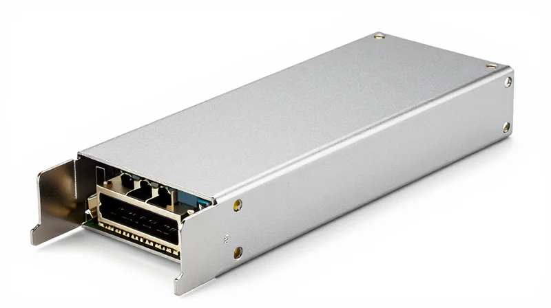
The 400G FR4 module represents a middle ground in the power consumption spectrum, typically drawing between 9W and 10.5W. While it consumes slightly more power than parallel-fiber alternatives like the DR4 due to the complexity of multiplexing four wavelengths onto a single fiber pair, it remains significantly more efficient than long-reach modules like the LR4. In a hyperscale environment, these marginal differences in wattage per port aggregate into substantial impacts on Power Usage Effectiveness (PUE) and the total cost of ownership (TCO) for networking infrastructure.
Comparative Power Profiles: FR4 vs. Alternatives
| Module Type | Typical Power Consumption | Reach | Key Power Driver |
|---|---|---|---|
| 400G SR8 | 7.5W - 9.0W | 100m | VCSEL Drivers |
| 400G DR4 | 8.0W - 10.0W | 500m | DSP & Silicon Photonics |
| 400G FR4 | 9.0W - 10.5W | 2km | DSP & CWDM Mux/Demux |
| 400G LR4 | 12.0W - 14.0W | 10km | TEC Cooling & High-Power EML |
The power consumption of the FR4 is primarily driven by the Digital Signal Processor (DSP) required for PAM4 modulation and the integrated cooling requirements of the lasers. Unlike the LR4, which often requires Thermo-Electric Coolers (TECs) to maintain precise wavelength stability over 10km, many FR4 designs utilize uncooled CWDM lasers, allowing them to stay within the 10W envelope. This power efficiency makes the FR4 ideal for high-density leaf-spine architectures where thermal headroom is limited.
The Scaling Effect: OpEx and Thermal Management
When scaling to a 128-port 400G switch, the difference between a 10W FR4 module and a 14W LR4 alternative becomes stark. A fully loaded chassis using FR4 modules would draw approximately 1,280W just for the optics. Moving to LR4 would increase that to nearly 1,800W. This 500W delta per switch does not just represent electricity costs; it necessitates more aggressive airflow and lower ambient inlet temperatures, which further inflates the facility's cooling budget.
Cooling Overhead and PUE
Data centers typically operate with a PUE ratio where every 1W consumed by IT equipment requires an additional 0.5W to 1W for cooling and power distribution. Consequently, a 10W FR4 module actually costs the facility between 15W and 20W of total energy. By staying at or below the 10W threshold, FR4 modules allow network engineers to maximize port density without exceeding the thermal limits of standard air-cooled racks.
Frequently Asked Questions: Power & Heat
- Why does the 400G FR4 consume more power than the DR4?
The FR4 requires additional internal components for Coarse Wavelength Division Multiplexing (CWDM) to combine four signals onto one fiber. The precision required for these lasers typically results in a slightly higher power draw compared to the parallel-fiber DR4 approach. - Can FR4 modules run in 'Low Power' mode?
Most 400G DSPs support power-saving features that can reduce consumption by disabling unused features or optimizing voltage, but the baseline power is largely dictated by the optical components and the PAM4 processing requirements. - How does heat affect the lifespan of an FR4 module?
Sustained operation at the upper limit of the module's temperature range (usually 70°C case temperature) can accelerate laser degradation. Efficient 10W designs help maintain a safer thermal margin compared to higher-wattage alternatives.
Fiber Infrastructure: Single-Mode vs. Multi-Mode Costs
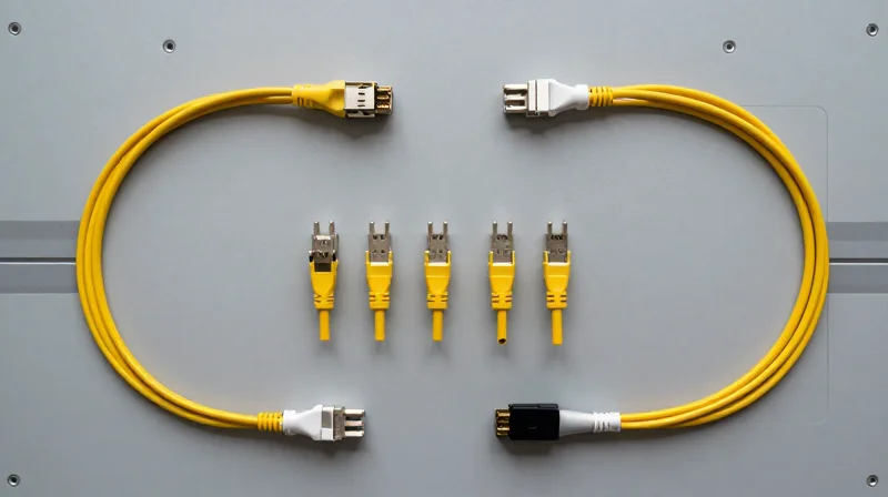
The Economic Impact of Fiber Infrastructure: SMF vs. MMF
The total cost of ownership (TCO) for 400G networking is heavily dictated by the fiber plant, where 400G FR4 modules offer a superior balance between transceiver price and cabling density. While short-reach solutions like SR8 rely on expensive Multi-Mode Fiber (MMF) and high-density MPO connectors, and DR4 requires parallel Single-Mode Fiber (SMF) paths, FR4 utilizes a simple duplex LC interface. By multiplexing four wavelengths onto a single pair of fibers, FR4 reduces the required fiber count by 75% compared to DR4, making it the most cost-effective choice for medium-distance leaf-to-spine interconnects where the cost of high-fiber-count trunking is prohibitive.
Cabling Density and Component Comparison
| Feature | 400G FR4 | 400G DR4 | 400G SR8 |
|---|---|---|---|
| Fiber Type | Single-Mode (SMF) | Single-Mode (SMF) | Multi-Mode (OM4) |
| Connector Type | Duplex LC | MPO-12 | MPO-16 / MPO-12 |
| Fibers per Link | 2 Fibers | 8 Fibers | 16 Fibers |
| Max Distance | 2 km | 500 m | 100 m |
| Relative Cabling Cost | Lowest | Moderate | High (Material Cost) |
The Hidden Costs of Parallel Fiber Deployment
Deploying parallel fiber solutions such as DR4 or SR8 involves complexities beyond the raw cost of the glass. High-count MPO trunk cables require specialized testing equipment, more expensive high-density patch panels, and significantly more space in cable trays. Furthermore, the sensitivity of MPO connectors to dust and contamination increases operational maintenance costs. In contrast, 2-fiber LC-based systems like FR4 leverage existing 10G, 40G, and 100G single-mode infrastructure. This allows data center operators to upgrade to 400G without a complete overhaul of their patch fields, preserving existing capital investments and reducing labor hours during migration.
Fiber Infrastructure FAQ
- Why is Single-Mode Fiber (SMF) preferred for 400G reaches over 100m?
SMF offers significantly lower attenuation and avoids the modal dispersion issues inherent in Multi-Mode Fiber (MMF), which struggles to maintain signal integrity at 400G speeds over longer distances. - When does 400G DR4 cabling become more expensive than FR4?
While DR4 transceivers are generally cheaper than FR4, the cabling infrastructure costs typically exceed FR4 once the link distance surpasses 100-150 meters due to the 4x increase in fiber strands required. - Can I use existing 100G CWDM4 fiber for 400G FR4?
Yes. 400G FR4 is specifically designed to be compatible with standard duplex single-mode fiber plants, making it a seamless drop-in upgrade for existing 100G CWDM4 or PSM4-to-LC architectures.
Transmission Reach: Finding the Sweet Spot for 2km
The 400G FR4 module represents the 'Goldilocks' zone of data center interconnects, providing a 2km reach that perfectly bridges the gap between the 500m limit of DR4 and the 10km long-haul capability of LR4. By utilizing Coarse Wavelength Division Multiplexing (CWDM) over duplex single-mode fiber, FR4 offers the most economical path for scaling spine-to-core links without the excessive hardware costs associated with long-reach optics or the complex cabling requirements of parallel fiber solutions.
The 2km Requirement in Leaf-Spine Architectures
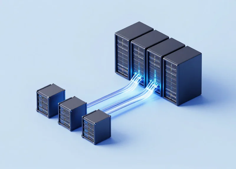
In modern hyperscale data centers, the physical distance between leaf and spine switches often exceeds the 500-meter threshold of DR4 optics, particularly in campus-wide deployments where multiple buildings are interconnected. While 400G DR4 is excellent for top-of-rack (ToR) to leaf connections, its reliance on parallel MPO-12 cabling becomes a significant cost driver as distances increase. 400G FR4 solves this by multiplexing four 100G signals onto a single pair of LC fibers, reducing the total fiber count and simplifying cable management for spans up to 2,000 meters.
Reach and Performance Comparison Matrix
| Module Type | Max Reach | Fiber Type | Optical Interface | Primary Application |
|---|---|---|---|---|
| 400G DR4 | 500m | Parallel SMF | MPO-12/MPO-8 | Intra-rack / ToR-Leaf |
| 400G FR4 | 2km | Duplex SMF | Duplex LC | Leaf-Spine / Intra-Campus |
| 400G LR4 | 10km | Duplex SMF | Duplex LC | Inter-Campus / Metro DCI |
Why 400G FR4 Wins Over LR4 for Campus Spans
While 400G LR4 can easily cover the 2km distance, it is engineered for 10km reaches, necessitating more powerful and expensive laser components. Choosing LR4 for a 2km link results in 'over-speccing' the network, leading to significantly higher capital expenditure (CapEx) without a performance benefit. Furthermore, LR4 modules typically consume more power and generate more heat, which increases long-term operational costs (OpEx) when deployed across thousands of ports.
- Can I use 400G FR4 for distances shorter than 2km?
Yes, 400G FR4 is fully compatible with shorter distances. It is often used for links as short as 100m when the existing fiber plant is duplex LC and the user wants to avoid upgrading to MPO cabling. - What is the main cost advantage of FR4 over DR4 for 2km?
The primary advantage is fiber infrastructure. For a 2km span, laying and maintaining a 12-fiber MPO cable (required for DR4) is significantly more expensive than a 2-fiber LC cable (required for FR4). - Is there a performance penalty for using CWDM in FR4?
Minimal. While multiplexing introduces slight insertion loss, the link budget of 400G FR4 is specifically designed to handle the 2km distance with high reliability and low bit-error rates (BER) using standard FEC.
Total Cost of Ownership (TCO) Breakdown

Determining the true value of 400G FR4 requires looking beyond the initial transceiver sticker price to include the 'hidden' costs of cabling density, installation labor, and cumulative energy consumption. While 400G DR4 modules may boast a lower per-unit purchase price, the requirement for expensive MPO-12 or MPO-8 cabling often makes the total system cost of FR4 significantly lower in data center environments where 2km reach and duplex LC fiber reuse are prioritized.
CapEx Comparison: Transceivers and Cabling Infrastructure
Capital expenditure (CapEx) accounts for roughly 60-70% of the initial TCO. The primary advantage of the FR4 module lies in its use of CWDM technology to transmit four wavelengths over a single pair of fibers, whereas DR4 requires parallel ribbons. This distinction drastically alters the budget for structured cabling.
| Cost Component | 400G FR4 (CWDM) | 400G DR4 (Parallel) | 400G LR4 (LWDM) |
|---|---|---|---|
| Transceiver Unit Cost | Moderate ($$$) | Low-Moderate ($$) | High ($$$$) |
| Fiber Type Required | Duplex LC SMF | MPO-12/MPO-8 SMF | Duplex LC SMF |
| Cabling Complexity | Low (2 fibers/link) | High (8 fibers/link) | Low (2 fibers/link) |
| Patch Panel Density | High (LC Duplex) | Medium (MPO) | High (LC Duplex) |
OpEx and 5-Year Lifecycle Modeling
Operational expenditure (OpEx) is dominated by power consumption and the cooling required to offset thermal output. Over a five-year period, the energy efficiency of the silicon photonics or EML lasers used in FR4 modules impacts the data center's PUE (Power Usage Effectiveness) and overall utility billing.
| TCO Metric (Per 100 Links) | 400G FR4 | 400G DR4 | 400G LR4 |
|---|---|---|---|
| Initial Hardware & Cabling | $85,000 | $92,000 | $145,000 |
| 5-Year Power Consumption | ~43,800 kWh | ~39,400 kWh | ~52,500 kWh |
| Cooling & Facility Overhead | Moderate | Low-Moderate | High |
| Total 5-Year TCO Estimate | $115,000 | $122,000 | $185,000 |
Financial Decision Factors
- When is FR4 the most cost-effective?
When upgrading existing 100G CWDM4 infrastructure, as it allows for the reuse of existing duplex LC fiber, eliminating the need for expensive new cable pulls. - How does DR4 impact long-term costs?
DR4 requires more fiber strands per link. While the modules are cheaper, the cost of MPO cabling and the increased physical space required in cable trays can lead to higher long-term OpEx. - What is the premium for LR4?
LR4 carries a significant price premium (often 2x the cost of FR4) due to the tighter tolerances of LWDM lasers and the 10km reach capability, making it a poor TCO choice for spans under 2km. - Do thermal loads affect the TCO?
Yes. FR4 modules typically consume between 10W and 12W. Modules with lower power consumption reduce the cooling load on the HVAC system, providing incremental OpEx savings at scale.
Future-Proofing: Interoperability and 800G Migration
Future-Proofing Your Network with 400G FR4
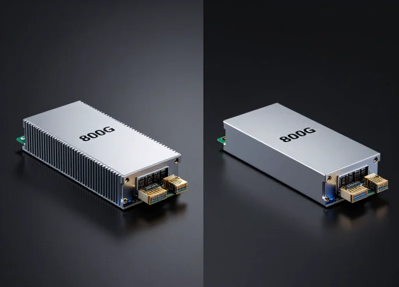
400G FR4 modules represent more than just a 2km reach solution; they are a strategic bridge to the 800G era because they utilize 100G PAM4 signaling per optical lane. This architecture aligns perfectly with the electrical interfaces of next-generation 800G switches, which typically utilize 8x100G lanes. By adopting FR4 now, data center operators ensure that their current fiber plant investments—specifically duplex single-mode fiber—remain viable as they transition to 800G and eventually 1.6T hardware, avoiding the costly 'rip and replace' cycles associated with parallel MPO cabling.
The Migration Path: From 400G to 800G
| Metric | 400G FR4 | 800G (2x400G FR4) | 800G DR8 |
|---|---|---|---|
| Optical Lanes | 4 x 100G (CWDM) | 8 x 100G (Dual CWDM) | 8 x 100G (Parallel) |
| Fiber Type | Duplex SMF | Dual Duplex SMF | MPO-12/16 SMF |
| Connector | LC/CS | Dual LC / CS / SN | MPO-12/16 |
| Reach | 2km | 2km | 500m |
| Backward Compatibility | Native | High (Breakout) | Moderate (MPO-Specific) |
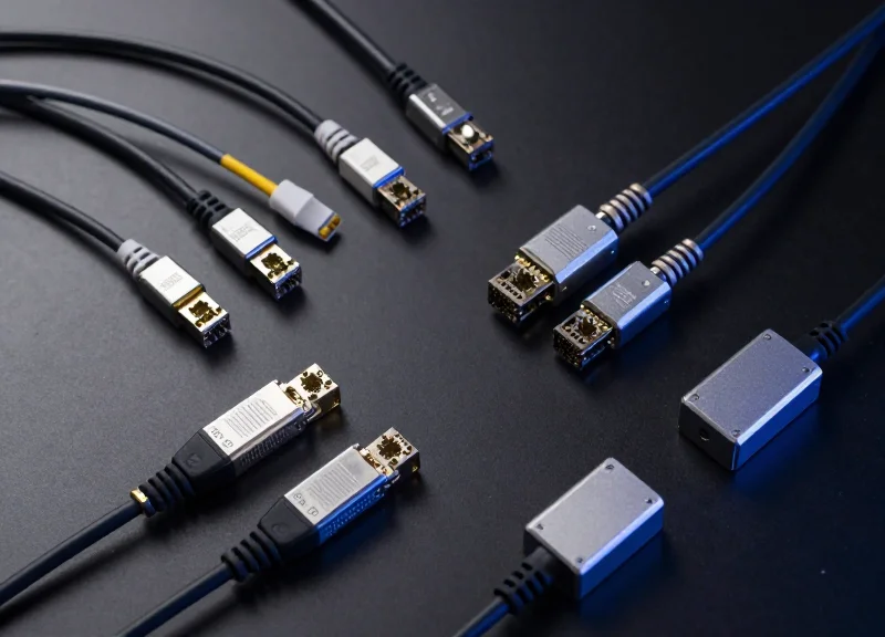
The shift to 800G often involves the use of 2x400G FR4 modules in OSFP or QSFP-DD800 form factors. These modules effectively house two 400G FR4 engines, allowing a single 800G port to talk to two legacy 400G FR4 ports using a simple breakout cable. This backward compatibility is a significant advantage for FR4 over DR4 alternatives, as it maintains the use of standard LC patch cords and reduces the complexity of the structured cabling system.
Ecosystem Maturity and Interoperability
The 100G Lambda MSA (Multi-Source Agreement) has fostered a robust ecosystem for FR4 technology. This maturity ensures that 400G FR4 modules from different vendors are highly interoperable, which is critical when scaling to 800G. As the industry moves toward 200G-per-lane signaling for 1.6T systems, the experience gained in managing the four-wavelength CWDM grid of FR4 will be the foundation for next-generation FR8 and LR8 solutions.
- Can 400G FR4 modules connect to 800G ports?
Yes, 800G switches can support 400G FR4 modules via breakout cables or by using 2x400G-FR4 modules that treat the 800G port as two independent 400G interfaces. - Will my current fiber support 1.6T upgrades?
The duplex single-mode fiber used for 400G FR4 is the most future-proof medium available, as future 1.6T standards (8x200G) continue to prioritize SMF for both power efficiency and reach. - Why is FR4 better for migration than DR4?
FR4 uses WDM to minimize fiber count. Migrating with DR4 at 800G (DR8) requires 16 fibers per link, which rapidly consumes conduit space and increases cable management complexity compared to the 2-fiber or 4-fiber paths of FR4/2xFR4.
In conclusion, the decision to deploy 400G FR4 is a move toward long-term operational stability. It balances current performance needs with a clear, low-complexity path to 800G, ensuring that the network can scale in density without requiring a fundamental redesign of the physical layer.
In conclusion, while 400G FR4 offers a superior balance of reach and fiber efficiency, the optimal choice depends on your existing cable plant and specific workload requirements. Balancing performance against TCO is the key to a scalable network. Ready to optimize your data center? Contact our engineering team for a customized 400G infrastructure audit and quote.