As data centers transition from 100G to 400G and beyond, the 200G QSFP56 SR4 has emerged as a critical intermediate solution for high-density networking. This article provides a comprehensive technical analysis of the QSFP56 SR4 form factor, explaining its modulation technology and how it solves the bandwidth bottlenecks in modern high-performance computing environments.
Introduction to the 200G Networking Ecosystem

Introduction to the 200G Networking Ecosystem
The 200G networking ecosystem represents a pivotal shift in data center architecture, moving beyond the bandwidth limitations of Non-Return-to-Zero (NRZ) signaling to adopt Four-Level Pulse Amplitude Modulation (PAM4). While 100G was the long-standing industry workhorse, the exponential growth of AI/ML workloads and hyper-scale cloud computing necessitated a throughput increase that was more cost-effective and thermally efficient than early-generation 400G deployments. The 200G QSFP56 SR4 standard emerged as the pragmatic solution, doubling the capacity of standard 100G QSFP28 interfaces while maintaining the familiar four-lane form factor.
The Strategic Bridge: 100G vs. 200G vs. 400G
In the evolution of Ethernet standards, 200G serves as a vital transition point. It utilizes the same 50G-per-lane electrical signaling foundation as 400G, but by limiting the configuration to four lanes, it avoids the extreme power density and cooling challenges often associated with early 400G QSFP-DD modules. This makes 200G an ideal upgrade path for enterprises that require more than 100G but are not yet ready to overhaul their entire cooling and power infrastructure for a full 400G core.
| Feature | 100G (QSFP28) | 200G (QSFP56) | 400G (QSFP-DD) |
|---|---|---|---|
| Modulation | NRZ | PAM4 | PAM4 |
| Lanes | 4 x 25G | 4 x 50G | 8 x 50G |
| Bits Per Clock | 1 Bit | 2 Bits | 2 Bits |
| Typical Application | Enterprise Edge | Data Center Aggregation | Cloud/Hyperscale Core |
Common Questions on 200G Adoption
- Why choose 200G over jumping straight to 400G?
200G offers a lower price-per-bit than 100G while maintaining a much lower power consumption and heat profile than 400G, making it more reliable for high-density Top-of-Rack (ToR) switching. - Is 200G QSFP56 backward compatible with 100G?
Physically, QSFP56 ports can often accept QSFP28 modules, but since 200G uses PAM4 modulation and 100G uses NRZ, they are not natively interoperable without a switch that supports multi-rate configurations or the use of a gearbox. - What is the primary driver for 200G SR4?
The primary driver is the need for short-reach (SR) multi-mode fiber connectivity in high-performance computing (HPC) environments where low latency and high bandwidth are critical.
The Evolution: From QSFP28 to QSFP56
The Technological Leap: From QSFP28 to QSFP56
The evolution from QSFP28 to QSFP56 is defined by a significant leap in signaling efficiency rather than a change in physical dimensions. While both standards utilize the Quad Small Form-factor Pluggable (QSFP) architecture, QSFP56 doubles the aggregate throughput from 100Gbps to 200Gbps by transitioning from Non-Return to Zero (NRZ) signaling to 4-level Pulse Amplitude Modulation (PAM4). This allows the 200G QSFP56 SR4 to transmit 50Gbps per lane across four channels, providing a high-density, cost-effective upgrade path for data centers hitting the bandwidth limits of 100G infrastructure.
Physical Comparison and Data Rates
| Feature | QSFP28 (100G) | QSFP56 (200G) |
|---|---|---|
| Max Data Rate | 103.1 Gbps | 212.5 Gbps |
| Modulation | NRZ | PAM4 |
| Lanes | 4 x 25G | 4 x 50G |
| Form Factor | SFF-8665 | SFF-8665 (Enhanced) |
| Fiber Compatibility | OM3/OM4 MPO-12 | OM3/OM4 MPO-12 |
Backward Compatibility and Infrastructure Reuse
One of the primary advantages of the QSFP56 standard is its mechanical backward compatibility. Because the external dimensions of the module and the MPO-12 connector interface remain unchanged, QSFP56 transceivers can physically fit into legacy QSFP28 and QSFP+ ports. However, the compatibility is primarily 'downward.' A 200G QSFP56 port on a switch can often support a 100G QSFP28 module by adjusting the internal SerDes from PAM4 to NRZ mode. Conversely, a legacy 100G switch cannot support a 200G module because it lacks the hardware required to process PAM4 signals.
Common Questions on the QSFP Evolution
- Does QSFP56 use the same fiber cabling as QSFP28?
Yes, the 200G QSFP56 SR4 uses the same MPO-12 multi-mode fiber connectors as the 100G QSFP28 SR4, allowing organizations to upgrade their hardware without replacing existing fiber plant. - Why is PAM4 necessary for 200G?
PAM4 carries two bits of information per symbol compared to one bit for NRZ. This effectively doubles the bandwidth without requiring a corresponding increase in electrical frequency, which would cause significant signal integrity issues over copper and optical components. - Can I mix QSFP28 and QSFP56 on the same switch?
Generally, yes. Most modern 200G/400G switches are designed to be multi-rate, allowing individual ports to be configured for either 100G (NRZ) or 200G (PAM4) operation depending on the module inserted.
Core Technical Specifications of QSFP56 SR4
Core Technical Specifications of QSFP56 SR4
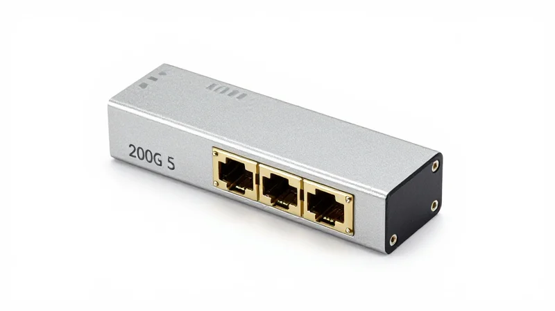
The 200G QSFP56 SR4 (Short Reach 4-channel) is a hot-pluggable optical transceiver designed for high-density 200 Gigabit Ethernet links over multi-mode fiber (MMF). It operates on a center wavelength of 850nm and leverages four independent transmit and receive channels, each capable of 53.125 Gbps data rates. By utilizing advanced PAM4 modulation, the module achieves a total aggregate bandwidth of 212.5 Gbps while maintaining the compact QSFP form factor.
Optical and Electrical Interface Characteristics
The QSFP56 SR4 utilizes a 4x50G electrical interface (200GAUI-4) to communicate with the host switch or router. Internally, the module converts these electrical signals into optical pulses using a VCSEL (Vertical-Cavity Surface-Emitting Laser) array. To manage signal integrity at these high frequencies, the module includes integrated Digital Diagnostic Monitoring (DDM) and a robust Clock and Data Recovery (CDR) circuit on both the transmitter and receiver paths.
| Parameter | Specification Detail |
|---|---|
| Aggregate Data Rate | 212.5 Gbps (4x 53.125 Gbps) |
| Modulation Type | PAM4 (4-level Pulse Amplitude Modulation) |
| Wavelength | 850 nm |
| Connector Type | MPO-12 / MTP-12 (Male/Pinned) |
| Typical Power Consumption | Less than 5 Watts |
| Operating Temperature | 0°C to 70°C (Commercial Grade) |
Transmission Distances and Fiber Requirements
Because the SR4 variant relies on multi-mode fiber, its maximum reach is limited by modal dispersion. Performance varies significantly based on the grade of fiber optic cabling deployed within the data center. While OM3 is supported for legacy environments, OM4 or OM5 is highly recommended for standard 200G deployments to ensure sufficient link margins.
| Fiber Type | Modal Bandwidth | Maximum Reach |
|---|---|---|
| OM3 MMF | 2000 MHz*km | 70 Meters |
| OM4 MMF | 4700 MHz*km | 100 Meters |
| OM5 MMF | 4700 MHz*km | 100 Meters |
- Why does QSFP56 SR4 use PAM4 instead of NRZ?
PAM4 allows the module to transmit two bits of information per symbol, effectively doubling the data rate of NRZ within the same bandwidth. This transition was essential to move from 100G (4x25G NRZ) to 200G (4x50G PAM4) without requiring more fiber lanes. - Can I use a QSFP56 SR4 with an MPO-12 unpinned cable?
No, the QSFP56 SR4 transceiver typically features a male (pinned) MPO-12 interface. Therefore, it requires a female (unpinned) MPO-12 patch cable to establish a proper connection. - Is the SR4 module compatible with breakout applications?
Yes, it is commonly used in breakout scenarios where a 200G port is split into 4x50G links using an MPO-to-LC breakout cable, connecting to four SFP56 SR transceivers.
The Role of PAM4 Modulation in 200G Optics

The transition to 200G QSFP56 SR4 is fundamentally driven by Pulse Amplitude Modulation 4-level (PAM4), a signaling technique that doubles the bandwidth efficiency of optical links. While previous 100G generations relied on Non-Return to Zero (NRZ) signaling, PAM4 allows each of the four lanes in a QSFP56 module to carry 50Gbps of data. By utilizing four distinct signal levels to represent combinations of two bits, PAM4 achieves the required 200G aggregate throughput without requiring an unattainable increase in the physical baud rate or fiber count.
How PAM4 Differs from NRZ
In traditional NRZ signaling, the signal exists in one of two states: high or low, representing a binary 1 or 0. To reach 200G using NRZ, the hardware would need to operate at extremely high frequencies, leading to significant signal degradation and electromagnetic interference. PAM4 solves this by using four voltage levels (0, 1, 2, 3), which correspond to the bit pairs 00, 01, 10, and 11. This effectively halves the required Nyquist frequency for a given data rate, allowing 50Gbps transmission per lane at a 25Gbaud rate.
| Feature | NRZ (100G QSFP28) | PAM4 (200G QSFP56) |
|---|---|---|
| Voltage Levels | 2 (High/Low) | 4 (0, 1, 2, 3) |
| Bits Per Symbol | 1 Bit | 2 Bits |
| Baud Rate per 50G Lane | 50 Gbaud | 25 Gbaud |
| Signal-to-Noise Ratio | High (Better) | Lower (More Sensitive) |
| Spectral Efficiency | 1 bit/Hz | 2 bits/Hz |
Signal Integrity and Forward Error Correction (FEC)
While PAM4 provides superior spectral efficiency, it introduces challenges regarding signal-to-noise ratio (SNR). Because the four voltage levels are spaced more closely together than the two levels in NRZ, the signal is more susceptible to noise and jitter. To compensate for this, 200G QSFP56 SR4 optics utilize mandatory Forward Error Correction (FEC). FEC algorithms add redundant data to the transmission, allowing the receiving end to identify and correct bit errors caused by the tighter tolerances of PAM4 signaling, ensuring a reliable Link Bit Error Rate (BER).
Frequently Asked Questions About PAM4
- Why was PAM4 chosen over increasing the NRZ clock speed?
Increasing NRZ clock speeds to 50Gbaud or higher causes massive signal loss (attenuation) in electrical traces and optical components. PAM4 allows 50G data rates at 25Gbaud, staying within the manageable thermal and electrical limits of the QSFP form factor. - Does PAM4 increase latency in 200G networks?
Yes, slightly. The requirement for Forward Error Correction (FEC) to process PAM4 signals adds a small amount of nanosecond-scale latency compared to the FEC-free or lighter FEC modes used in some NRZ 100G applications. - Is PAM4 backward compatible with NRZ?
Technically, the modulations are different. While some modern DSPs (Digital Signal Processors) can support both, a 200G QSFP56 port must specifically support 'breakout' modes or speed-down functions to communicate with older 100G NRZ QSFP28 modules.
Connectivity and Cabling: The MPO-12 Interface
Connectivity and Cabling: The MPO-12 Interface
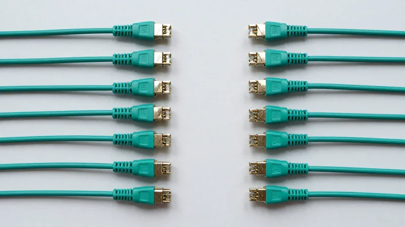
The 200G QSFP56 SR4 optical module utilizes a female MPO-12 (Multi-fiber Push-On) connector interface, which is the industry standard for short-reach parallel optics. Unlike single-mode optics that often rely on duplex LC connectors, the SR4 design uses four discrete lanes for transmission and four for reception. This necessitates a multi-fiber ribbon or patch cable capable of aligning multiple fibers simultaneously. To ensure high-speed signal integrity at 200G, the physical interface relies on precise alignment pins and a Physical Contact (PC) polish to minimize back-reflection and insertion loss across the eight active fiber strands.
Fiber Media and Reach Specifications
To achieve the full 200G throughput, these transceivers require Laser-Optimized Multi-Mode Fiber (LOMMF). While the technology is backward compatible with older fiber grades, the maximum reach is strictly dictated by the modal bandwidth of the cable. OM4 and OM5 fibers are strongly recommended for new deployments to provide the necessary headroom for PAM4 signal modulation, which is more sensitive to chromatic dispersion than traditional NRZ signals.
| Fiber Type | Cabling Standard | Max Reach (200G SR4) |
|---|---|---|
| OM3 | 50/125 ΙΙΙ | 70 Meters |
| OM4 | 50/125 ΙΙΙΙ | 100 Meters |
| OM5 | 50/125 WBMMF | 100 Meters |
MPO-12 Lane Mapping and Polarity
The MPO-12 interface for SR4 does not use all 12 available fiber positions. Instead, it follows a standard 8-fiber layout: the four leftmost fibers (Positions 1, 2, 3, 4) are dedicated to the Transmit (TX) channels, while the four rightmost fibers (Positions 9, 10, 11, 12) are used for the Receive (RX) channels. The central four positions (5, 6, 7, 8) remain unused. Maintaining the correct polarity is critical; typically, a 'Type B' (Cross-over) MPO cable is used to connect two transceivers directly, ensuring the TX lanes on one end align with the RX lanes on the other. Using the wrong polarity will result in a total link failure as the light pulses will hit the inactive central pins or the wrong directional components.
- Can existing 100G MPO cables be used?
Yes, since both 100G QSFP28 SR4 and 200G QSFP56 SR4 use the same MPO-12 interface and 8-fiber pinout, existing OM4 cabling infrastructure is generally compatible. - Why is OM3 reach limited to 70m?
OM3 fiber has lower modal bandwidth than OM4, leading to increased inter-symbol interference (ISI) when processing high-frequency PAM4 signals at 50Gbps per lane. - What is the significance of the female MPO connector?
The QSFP56 SR4 transceiver contains alignment pins (male); therefore, the patch cable must be a female MPO connector (without pins) to ensure proper mating.
Power Consumption and Thermal Management
Power Consumption and Thermal Management
The 200G QSFP56 SR4 transceiver typically operates within a power envelope of 4.5W to 5.0W, representing a significant engineering achievement in energy efficiency for 200GbE throughput. By leveraging 50G PAM4 signaling, these modules provide double the bandwidth of previous 100G generations while maintaining a manageable thermal footprint that fits within the standard power classes defined by the MSA (Multi-Source Agreement) for the QSFP56 form factor.
Energy Efficiency: QSFP56 vs. Previous Generations
While the absolute power consumption of a 200G module is higher than its 100G predecessor, the efficiency per gigabit is vastly improved. The integration of 7nm Digital Signal Processors (DSPs) allows the QSFP56 SR4 to handle complex error correction and modulation with minimal leakage current. This balance is critical for large-scale leaf-spine architectures where power-over-provisioning can lead to excessive operational costs.
| Parameter | 100G QSFP28 SR4 | 200G QSFP56 SR4 |
|---|---|---|
| Typical Power Consumption | 2.5W - 3.5W | 4.0W - 5.0W |
| Modulation Type | 25G NRZ | 50G PAM4 |
| Power Per Gigabit | ~30mW / Gbps | ~22.5mW / Gbps |
| Max Case Temperature | 70°C | 70°C |
Cooling Requirements and Airflow Management
Thermal management in high-density switches requires a multi-layered approach. Because the 200G QSFP56 SR4 dissipates nearly 5W of heat in a very small volume, airflow velocity must be strictly maintained. In a 32-port or 64-port 1U switch, the aggregate thermal load from transceivers alone can exceed 300W. To prevent 'thermal throttling' or permanent hardware failure, network operators must ensure that the switch's cooling fans are configured for the correct airflow direction (port-side intake or exhaust) to match the data center's hot-aisle/cold-aisle containment strategy.
- Does 200G QSFP56 SR4 require active cooling?
Yes, these modules rely on the host system's active cooling (fans) and internal heatsinks. They cannot operate in a passive or still-air environment without exceeding their 70°C rated case temperature. - How does PAM4 impact heat dissipation?
PAM4 requires sophisticated DSP chips for signal processing and FEC (Forward Error Correction). These chips generate more heat than the simpler NRZ clock and data recovery (CDR) circuits used in 100G optics. - What happens if a module exceeds its thermal limit?
Most QSFP56 SR4 modules feature internal thermal sensors. If the temperature exceeds 70°C, the module may report a high-temperature alarm via the I2C interface, and if it continues to rise, the laser drivers may shut down to prevent permanent damage.
Comparative Analysis: QSFP56 vs. QSFP-DD
Comparative Analysis: QSFP56 vs. QSFP-DD
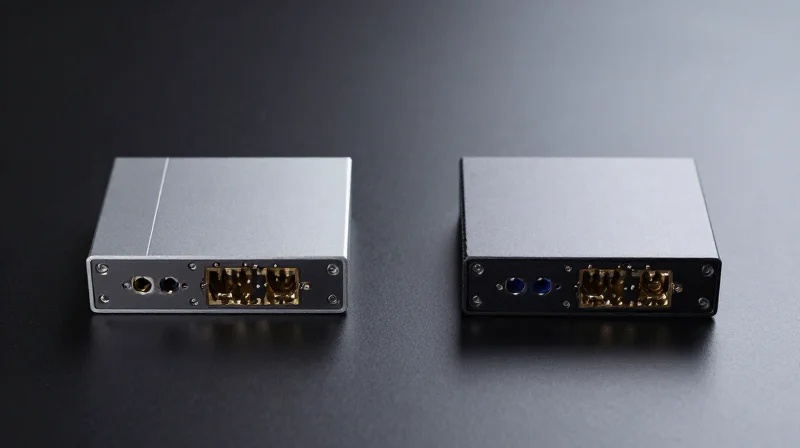
While both QSFP56 and QSFP-DD (Double Density) utilize PAM4 modulation to achieve high-speed data rates, they differ fundamentally in their electrical interface architecture and scaling potential. QSFP56 is an evolution of the 4-lane QSFP design, specifically optimized for 200G applications by running four 50G lanes. In contrast, QSFP-DD introduces an additional row of electrical contacts to provide an 8-lane interface, effectively doubling the density and enabling up to 400G or 800G throughput within the same physical footprint as a standard QSFP module.
| Feature | QSFP56 | QSFP-DD |
|---|---|---|
| Electrical Lanes | 4 Lanes (4 x 50G PAM4) | 8 Lanes (8 x 50G or 8 x 100G PAM4) |
| Maximum Bandwidth | 200 Gbps | 400 Gbps / 800 Gbps |
| Backwards Compatibility | QSFP+, QSFP28 | QSFP+, QSFP28, QSFP56 |
| Typical Power Usage | Lower (approx. 5W for SR4) | Higher (due to 8-lane circuitry) |
| Ideal Use Case | Dedicated 200G Core/Aggregation | Future-proofed 400G Data Centers |
Architectural Trade-offs and Scaling
The primary advantage of QSFP56 lies in its relative simplicity and power efficiency for 200G links. Because it maintains the 4-lane structure of previous QSFP generations, it presents fewer thermal management challenges than the 8-lane QSFP-DD. However, QSFP-DD is the superior choice for infrastructure longevity. A QSFP-DD port can accept a QSFP56 module, but a QSFP56 port cannot support the 8-lane requirements of a 400G QSFP-DD module. This makes QSFP-DD the standard for 400G-ready switches, while QSFP56 remains a targeted, high-efficiency solution for 200G-specific network tiers.
Common Questions: Form Factor Selection
- Can I plug a QSFP56 SR4 into a QSFP-DD port?
Yes. QSFP-DD ports are designed with backward compatibility in mind. The dual-row contact design allows it to interface seamlessly with the single-row contact layout of QSFP56 modules. - Why choose QSFP56 over QSFP-DD for 200G?
QSFP56 is often more cost-effective for pure 200G deployments. It consumes less power and generates less heat because it does not require the additional electrical traces and processing components needed to manage eight lanes. - Does QSFP-DD support the same MPO cabling as QSFP56?
For SR4 applications, both modules typically use the MPO-12 connector for multi-mode fiber. The difference is internal to the module's electrical signaling rather than the external optical interface.
Key Application Scenarios in Modern Data Centers

The 200G QSFP56 SR4 module serves as a critical bridge in the transition from legacy 100G networks to ultra-high-speed 400G and 800G environments. By utilizing PAM4 modulation over four lanes of multi-mode fiber, it offers a cost-effective, power-efficient solution for links within 100 meters, making it indispensable for high-bandwidth internal data center traffic.
Leaf-Spine Fabric Connectivity and Expansion
In modern 'clos' or leaf-spine architectures, the 200G QSFP56 SR4 is primarily utilized for leaf-to-spine uplinks. As data centers scale horizontally, the bottleneck often shifts to the fabric layer. 200G provides a 2x throughput increase over traditional 100G QSFP28 without requiring a total overhaul of existing MPO-12 cabling infrastructure. This allow for seamless capacity upgrades in enterprise and hyperscale facilities where fiber density is at a premium.
AI and Machine Learning Compute Clusters
Artificial Intelligence and Machine Learning workloads involve massive datasets distributed across GPU-accelerated servers. These clusters require reliable, high-speed interconnects for RDMA (Remote Direct Memory Access) over Converged Ethernet (RoCE). The 200G QSFP56 SR4 provides the necessary bandwidth for rapid parameter synchronization and data exchange between compute nodes, ensuring that processor idle time is minimized during deep learning training cycles.
High-Frequency Trading and Low-Latency Finance
In the realm of High-Frequency Trading (HFT), microseconds matter. Because the SR4 variant uses short-reach multi-mode fiber and avoids the complex digital signal processing (DSP) overhead found in long-range coherent optics, it maintains a lower latency profile. This makes it a preferred choice for connecting trading servers to switch fabrics within the same colocation hall where speed of execution is the primary competitive advantage.
| Scenario | Primary Requirement | Why 200G QSFP56 SR4 |
|---|---|---|
| Enterprise Cloud | Cost-Efficiency | Doubles bandwidth using existing MMF cabling. |
| AI Training | Throughput / RoCE | Supports high-speed RDMA for GPU clusters. |
| Edge Data Centers | Power Density | Lower power consumption per bit compared to 400G. |
| Financial Services | Minimal Latency | Short-reach optics avoid long-range signal processing. |
Application FAQ
- Can 200G QSFP56 SR4 be used for Data Center Interconnect (DCI)?
Typically no, as SR4 is limited to 100m over OM4 fiber. DCI usually requires FR4 or LR4 modules for longer distances. - Is it compatible with existing 100G infrastructure?
While the MPO-12 connector is the same, the modulation changes from NRZ to PAM4, meaning a gearbox or compatible switch port is required for interoperability. - What is the benefit of SR4 over breakout configurations?
SR4 allows for a direct 200G-to-200G connection, simplifying cable management compared to breaking 400G ports into 2x200G or 4x100G.
Interoperability and FEC Requirements
Ensuring seamless interoperability for 200G QSFP56 SR4 modules requires more than physical connector matching; it demands strict adherence to IEEE 802.3cd standards, particularly regarding Forward Error Correction (FEC). Because PAM4 signaling is more susceptible to noise than traditional NRZ, FEC acts as a critical mathematical buffer that corrects transmission errors at the receiver end, maintaining a post-FEC Bit Error Rate (BER) of less than 10^-15.
The Necessity of RS-FEC (544, 514)
The 200G QSFP56 SR4 specification utilizes Reed-Solomon Forward Error Correction, specifically defined as RS(544, 514), also known as KP-FEC. At 50G per lane, the eye opening in PAM4 signaling is significantly smaller than in 25G NRZ, leading to a higher pre-FEC Bit Error Rate. Without active error correction, the link would fail to meet the performance requirements of modern data center fabrics. It is important to note that FEC is not optional for 200G SR4; both the transmitting and receiving host ports must support and enable the same FEC algorithm to establish a stable link.
FEC Configuration and Performance Metrics
| Parameter | RS-FEC (KP4) | No FEC (Legacy) |
|---|---|---|
| Standard | IEEE 802.3cd | N/A (Not supported for 200G) |
| Overhead | Approx. 5.8% | 0% |
| Pre-FEC BER Limit | 2.4 x 10^-4 | 10^-12 (Required for Link) |
| Link Stability | High (Required for 200G) | Unstable / Non-functional |
Interoperability and Host Settings
While the QSFP56 form factor is physically compatible with some legacy ports, a 200G SR4 module will only operate at its native speed in a host port designed for QSFP56. Interoperability issues often arise when connecting equipment from different vendors if there is a mismatch in the FEC implementation or the 'Auto-Negotiation' status. For successful link-up, engineers must verify that the transceiver's internal EEPROM registers are correctly interpreted by the host's Network Operating System (NOS) to apply the correct KP4 FEC settings automatically.
- Can I turn off FEC on a 200G QSFP56 SR4 link?
No. FEC is mandatory for 200G PAM4 links to correct the errors inherent in multi-level signaling; disabling it will result in excessive packet loss or total link failure. - What happens if the FEC settings on two ends of a fiber don't match?
The link will typically remain in a 'Down' state or show as 'Link Up' with 100% packet loss, as the receiver cannot correctly decode the symbol stream without the proper FEC parity data. - Is RS-FEC (544, 514) the same as the FEC used in 100G?
No, 100G (QSFP28) often uses Base-R FEC or RS-FEC (528, 514), also known as KR-FEC. The RS(544, 514) used in 200G provides the stronger correction capabilities required for PAM4 symbols.
Future Outlook: The Longevity of 200G Solutions
Future Outlook: The Longevity of 200G Solutions
Despite the rapid ascent toward 800G and 1.6T, the 200G QSFP56 SR4 transceiver remains a cornerstone for enterprise and mid-tier data centers that prioritize a balanced ratio of cost-per-bit to power consumption. While hyperscalers are early adopters of the highest possible density, the 200G standard offers a stable, mature ecosystem for organizations transitioning from legacy 100G NRZ infrastructures to PAM4-based high-speed connectivity without the thermal complexities of 400G or 800G hardware.
Market Positioning vs. 400G and 800G
The longevity of 200G QSFP56 is largely tied to its backward compatibility and port density on existing 200G switches. Unlike 400G QSFP-DD, which requires more complex thermal management and often higher-cost optics, 200G QSFP56 utilizes the same physical footprint as 40G and 100G QSFP modules, simplifying the upgrade path for many existing rack layouts.
| Technology Tier | Current Status | Expected Longevity | Primary Use Case |
|---|---|---|---|
| 200G QSFP56 | Mature / Stable | 5 - 7 Years | Enterprise Core & AI Clusters |
| 400G QSFP-DD | Growth Phase | 7 - 10 Years | Cloud Provider Backbones |
| 800G OSFP/QSFP-DD | Early Adoption | 10+ Years | Hyperscale AI & ML Training |
Why 200G Remains Relevant
For many operators, 200G represents the 'efficiency peak' of current PAM4 technology. It provides a 2x bandwidth increase over 100G while maintaining manageable power envelopes (typically under 5W per module). As AI and ML workloads migrate from the hyperscale core to the enterprise edge, the demand for cost-effective 200G SR4 solutions is projected to see a secondary surge in volume.
- Is 200G QSFP56 becoming obsolete due to 400G?
No. While 400G is standard for massive cloud builds, 200G remains the preferred choice for enterprise data centers that do not yet require 400G bandwidth but need the efficiency of PAM4 signaling. - What is the primary factor limiting 200G's lifespan?
The transition to 112G SerDes technology in next-gen switches is the primary factor. However, backward compatibility through breakout cables and multi-rate ports will extend the utility of 200G modules for several years. - Should I invest in 200G now or wait for 400G prices to drop?
If your current switch fabric is 200G-based, the SR4 optics offer the lowest latency and highest reliability today. Waiting for 400G involves a full hardware refresh that may not be ROI-positive for another 3-4 years.
In conclusion, 200G QSFP56 SR4 is far from a bridge technology destined for a quick exit. Its role as a stable, efficient, and cost-predictable solution ensures it will remain a vital component of the data center interconnect landscape well into the late 2020s.
Understanding the technical nuances of 200G QSFP56 SR4 is essential for optimizing data center throughput and latency. By leveraging PAM4 modulation and efficient MPO-12 cabling, enterprises can scale their infrastructure effectively. Contact our engineering team today for a customized optical solution quote or to learn more about our 200G product line.