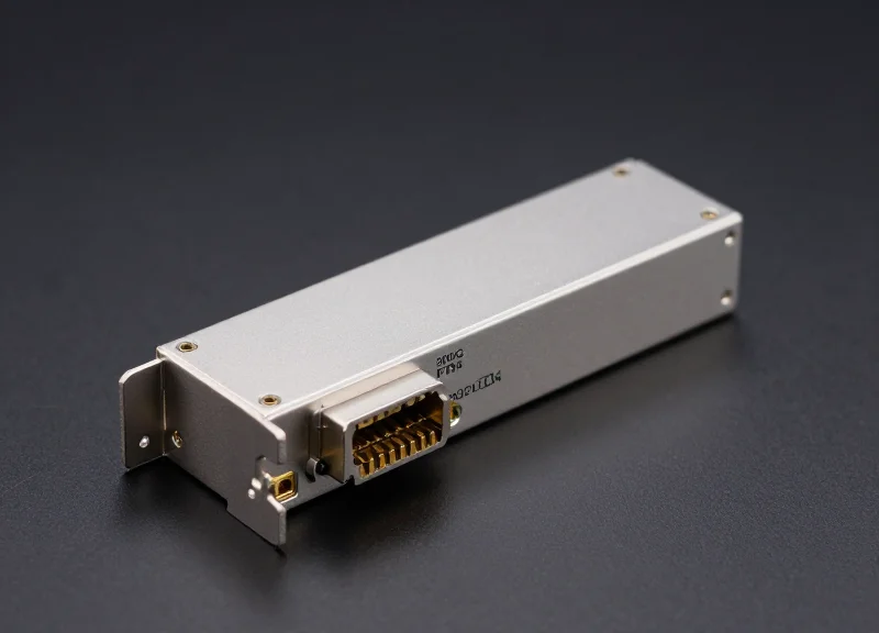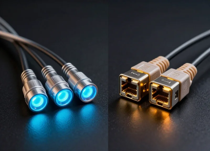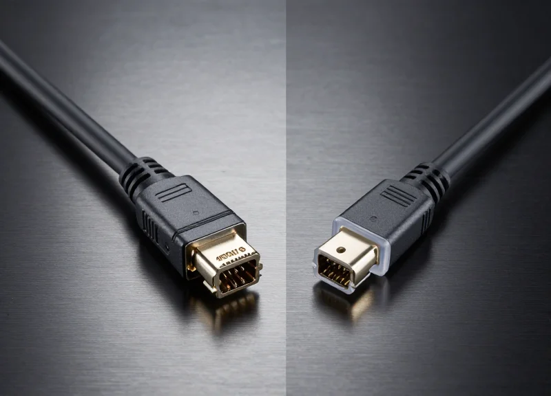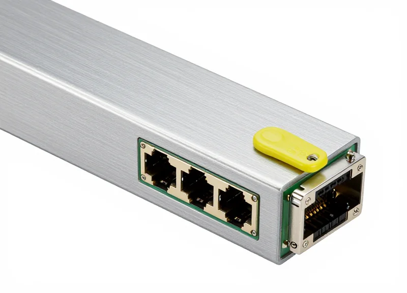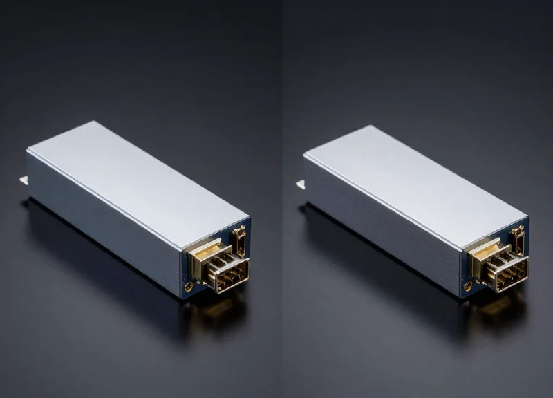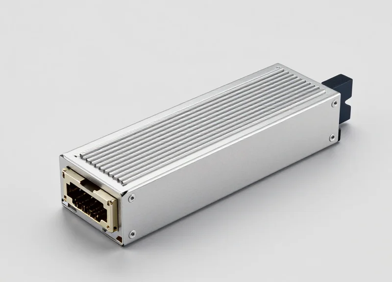
As data centers evolve to handle massive AI and machine learning workloads, 800G bandwidth is no longer a luxury but a necessity. The 800G OSFP DR8 transceiver stands at the forefront of this revolution, offering unparalleled density and performance. This guide explores the engineering behind the module and why it is becoming the preferred choice for hyperscale interconnects.
The Evolution to 800G Connectivity

The industry's move toward 800G connectivity is a necessary architectural leap to support the unprecedented data traffic generated by large-scale AI training and high-performance computing (HPC) environments. As modern data centers hit the throughput limits of 400G infrastructures, 800G provides the critical path to higher bandwidth, improved port density, and the efficient scaling required to prevent networking bottlenecks from idling expensive compute resources.
Key Drivers: The AI and ML Revolution
Artificial Intelligence and Machine Learning (AI/ML) clusters are the primary engines behind the 800G transition. These workloads rely on massive, low-latency interconnects to facilitate rapid communication and gradient synchronization between thousands of GPU nodes. By transitioning to 800G, operators can maintain the necessary radix in spine-leaf architectures while reducing the physical footprint and complexity of the cabling infrastructure.
| Metric | 400G Infrastructure | 800G Infrastructure |
|---|---|---|
| Max Throughput per Port | 400 Gbps | 800 Gbps |
| Electrical Lane Speed | 50G or 100G PAM4 | 100G or 200G PAM4 |
| Standard Form Factors | QSFP-DD / OSFP | OSFP / QSFP-DD800 |
| Primary Use Case | General Cloud Computing | AI/ML Training & HPC |
Scaling with Density and Thermal Efficiency
The evolution to 800G is not merely about raw speed; it addresses the physical constraints of the modern rack. Through the use of advanced form factors like OSFP, the industry can manage the significant heat generated by 800G optical engines. The OSFP design includes integrated heat sinks that allow for better thermal dissipation than previous generations, ensuring that as bandwidth density increases, the reliability and lifespan of the optics remain high.
- Why skip intermediate speeds and move directly to 800G?
The industry standardized on doubling the 400G rate to align with the development of 112G SerDes lanes and the natural capacity progression of switch silicon chips like Broadcom's Tomahawk series. - How does 800G impact data center latency?
By increasing per-port throughput and enabling flatter network topologies with fewer hops, 800G helps maintain the ultra-low latency required for synchronous AI compute tasks. - Is 800G backward compatible?
Most 800G OSFP ports are designed to be backward compatible with 400G modules using adapters or via specific breakout configurations, allowing for phased upgrades.
Understanding the OSFP Form Factor
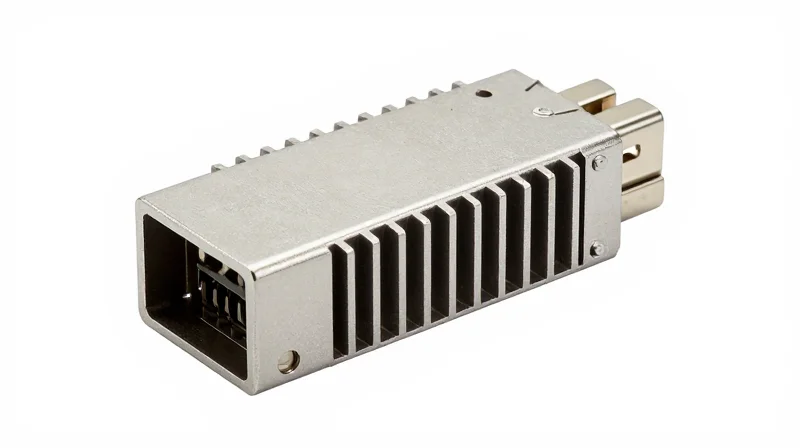
The Octal Small Form-factor Pluggable (OSFP) is a revolutionary transceiver design specifically engineered to overcome the physical and thermal limitations of previous generations. As data rates climb to 800G, the power consumption of Digital Signal Processors (DSPs) increases significantly, necessitating a form factor that can handle higher wattages without compromising performance or reliability.
Mechanical Design and the 'Octal' Advantage
The 'Octal' in OSFP refers to its eight-lane electrical interface. In the context of 800G OSFP DR8, each of these eight lanes operates at 100G using PAM4 modulation. Physically, the OSFP module is slightly wider and deeper than the QSFP-DD. This increased volume provides the necessary real estate for complex high-speed circuitry and, more importantly, allows for a more robust mechanical structure capable of housing advanced optical components.
Superior Thermal Management: The Integrated Heat Sink
Thermal management is the primary differentiator for the OSFP form factor. Unlike the QSFP-DD, which features a flat-top design that relies on a heat sink attached to the equipment's cage, the OSFP module incorporates an integrated heat sink directly onto the transceiver body. This design allows for better airflow contact and heat dissipation directly from the module's internal components to the ambient environment.
| Feature | OSFP Form Factor | QSFP-DD Form Factor |
|---|---|---|
| Thermal Design | Integrated heat sink (fins on module) | Flat top (requires cage heat sink) |
| Power Envelope | Supports up to 15W - 20W+ | Typically limited to 12W - 15W |
| Physical Size | Wider and deeper | More compact, legacy compatible |
| Airflow Efficiency | High (airflow passes through fins) | Moderate (relies on cage thermal path) |
Why Thermal Efficiency Matters for 800G
- Does OSFP support backward compatibility?
While not natively compatible with QSFP ports due to size differences, OSFP-to-QSFP adapters exist to allow older modules to work in OSFP slots. - What is the maximum power capacity of OSFP?
The OSFP specification is designed to handle up to 30W of power, making it future-proof for 1.6T and even 3.2T applications. - How does the heat sink affect port density?
The integrated heat sink allows OSFP to maintain high port density (up to 32 ports per 1U switch) by preventing thermal throttling in high-ambient-temperature environments.
By moving the heat sink from the switch cage to the module itself, OSFP simplifies the cooling requirements for switch manufacturers. This shift ensures that the most power-intensive component of the network—the transceiver—is self-optimized for cooling, which is critical for the dense 800G deployments found in modern AI clusters.
Decoding DR8: Distance and Lanes

Decoding the DR8 Nomenclature
In the context of 800G OSFP, 'DR8' refers to a specific set of optical specifications where 'DR' stands for Data-center Reach (typically defined as 500 meters over Single-Mode Fiber) and '8' represents the number of parallel optical lanes. This architecture deviates from Wavelength Division Multiplexing (WDM) by utilizing eight distinct fiber pairs—one transmit and one receive fiber per lane—to deliver a total aggregate bandwidth of 800Gbps. This design is specifically engineered to minimize latency and power consumption by simplifying the optical sub-assembly compared to long-reach alternatives.
The 500-Meter Reach: Bridging the Gap
The 500-meter distance is the industry standard for intra-datacenter connectivity within a single building. While Multi-Mode Fiber (MMF) solutions like SR8 are limited to 50–100 meters at these speeds, DR8 utilizes Single-Mode Fiber (SMF) to maintain signal integrity over longer spans without the dispersion issues inherent in MMF. This reach is ideal for connecting leaf switches to spine switches in modern Clos network topologies, providing sufficient overhead for even the largest hyperscale data center halls.
8-Lane Parallel Architecture and PAM4
The 800G DR8 module employs eight parallel lanes, each operating at 100Gbps using 53.125 GBaud PAM4 (Pulse Amplitude Modulation 4-level) signaling. By using eight lanes of 100G, the DR8 module offers a seamless breakout capability that is essential for network flexibility. A single 800G port can be broken down into eight 100G ports or two 400G ports (400G DR4), allowing network operators to interconnect older 100G/400G hardware with new 800G switches.
| Feature | 800G DR8 | 800G DR8+ | 800G 2xDR4 |
|---|---|---|---|
| Max Reach | 500 Meters | 2 Kilometers | 500 Meters |
| Fiber Type | Parallel SMF | Parallel SMF | Parallel SMF |
| Optical Lanes | 8 x 100G | 8 x 100G | 2 x (4 x 100G) |
| Connector Type | MPO-16 / 2xMPO-12 | MPO-16 | 2xMPO-12 |
Connectivity and Fiber Infrastructure Requirements
Because DR8 relies on parallel transmission rather than multiplexing, it requires a higher fiber count in the cabling infrastructure. The OSFP DR8 module typically uses an MPO-16 connector or a dual MPO-12 (2xMPO-12) interface. For data centers transitioning from 400G, the 2xMPO-12 variant is often preferred as it allows the 800G module to act as two independent 400G DR4 engines, simplifying the cable management and migration path.
Common Questions on DR8 Implementation
- Can 800G DR8 be used for 100G breakout?
Yes, the 8-lane structure is natively compatible with 100G DR standards. Using a breakout cable (MPO to 8xLC), a single 800G DR8 port can connect to eight individual 100G SFP112 or QSFP28 DR transceivers. - Why choose DR8 over FR8?
DR8 uses parallel fibers which reduces the complexity of the transceiver by removing the need for optical mux/demux components. This leads to lower power consumption and lower per-module costs, provided the fiber plant can support the higher strand count. - Is there a difference between DR8 and DR8+?
The 'plus' variant (DR8+) typically signifies an enhanced optical link budget that allows for distances up to 2km on single-mode fiber, whereas standard DR8 is capped at 500 meters.
The Power of 8x100G PAM4 Modulation
The Power of 8x100G PAM4 Modulation
The 800G OSFP DR8 achieves its massive 800Gbps aggregate throughput by utilizing eight parallel lanes, each transmitting at 100Gbps using 4-level Pulse Amplitude Modulation (PAM4). By doubling the bits per symbol compared to traditional signaling, PAM4 allows the module to meet the extreme bandwidth demands of modern AI and data center fabrics without requiring excessive physical bandwidth.
Understanding PAM4: Efficiency in Signaling
Unlike traditional Non-Return-to-Zero (NRZ) signaling, which transmits a single bit per clock cycle using two voltage levels, PAM4 utilizes four distinct signal levels. This allows each symbol to represent two bits of data (00, 01, 10, 11). By doubling the data density, PAM4 effectively halves the required Nyquist frequency for a given bit rate, making 100Gbps transmission technically feasible over standard single-mode fiber and electrical interfaces.
| Attribute | NRZ Signaling | PAM4 Signaling |
|---|---|---|
| Bits per Symbol | 1 Bit | 2 Bits |
| Voltage Levels | 2 (Low/High) | 4 (0, 1, 2, 3) |
| Symbol Rate for 100G | 100 GBaud | 50 GBaud |
| Signal-to-Noise Ratio | High Tolerance | Reduced (Requires DSP) |
The Critical Role of the DSP Chip
At the 800G scale, signal integrity becomes a significant challenge due to insertion loss, crosstalk, and chromatic dispersion. The Digital Signal Processor (DSP) within the OSFP DR8 module acts as the system's brain, performing high-speed analog-to-digital conversion and complex mathematical compensations. It ensures that the multi-level PAM4 signals are correctly sampled, equalized, and decoded at the receiving end, maintaining a low bit-error rate (BER).
- Why is PAM4 necessary for 800G?
Without PAM4, the baud rate required for 100G per lane would exceed the physical capabilities of current optical and electrical components, leading to unsustainable signal loss. - What does the DSP do for signal quality?
The DSP uses adaptive equalization and facilitates Forward Error Correction (FEC) to identify and fix bit errors caused by noise and signal degradation across the fiber link. - Does 800G DR8 support breakout modes?
Yes, the 8-lane architecture of the DR8 is specifically designed to support breakout configurations, such as 2x400G or 8x100G, providing flexibility in leaf-spine architectures.
Optical Interface and Connector Standards
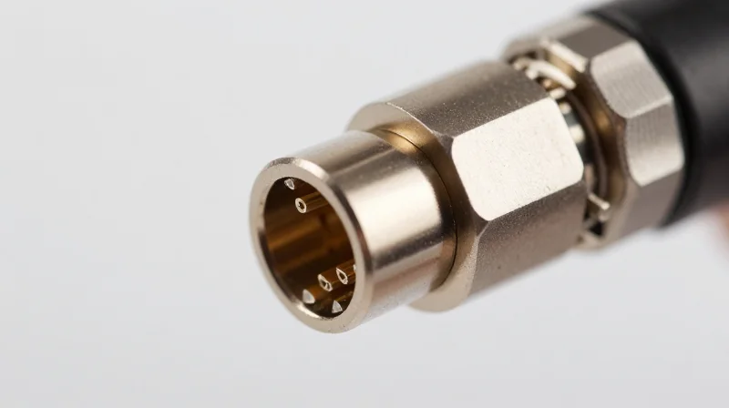
The optical interface of the 800G OSFP DR8 module is a critical engineering component that facilitates the physical connection between the transceiver's high-speed internal optics and the external fiber plant. To support an aggregate 800Gbps throughput across eight parallel 100G lanes, these modules utilize high-density multi-fiber push-on (MPO) connectors designed specifically for single-mode fiber (SMF) applications. The interface must manage exactly 16 fibers—8 for transmission (Tx) and 8 for reception (Rx)—ensuring precise alignment and minimal insertion loss to maintain signal integrity over its 500-meter reach.
The Shift to MPO-16 and Dual MPO-12 Architectures
While previous generations of transceivers often relied on the MPO-12 connector, the 800G DR8 standard necessitates a move toward higher fiber counts. The most common implementation for OSFP DR8 is the MPO-16 connector. This single-row interface provides a compact footprint that aligns perfectly with the eight-lane architecture of the transceiver. By using a single MPO-16 connector, data centers can simplify cable management while ensuring all 16 fibers are housed in a single ferrule. Alternatively, some specialized 2x400G configurations utilize dual MPO-12 connectors, allowing the 800G module to behave as two independent 400G ports for breakout applications.
| Connector Type | Fiber Configuration | Alignment Pins | Primary Use Case |
|---|---|---|---|
| MPO-16 (APC) | 16 Fibers (8 Tx, 8 Rx) | Male (Pinned) / Female | Standard 800G DR8 Native Connectivity |
| Dual MPO-12 (APC) | 24 Fibers (16 Active) | Dual Ferrules | 2x400G Breakout / Legacy Interop |
| MPO-24 (APC) | 24 Fibers (16 Active) | Three Rows or Single Row | High-Density Custom Trunks |
Ensuring Signal Integrity with APC Polishing
Due to the extreme sensitivity of 100G PAM4 (Pulse Amplitude Modulation) signaling, the optical interface for 800G DR8 exclusively employs Angled Physical Contact (APC) ferrules. Standard flat-polished (PC or UPC) connectors are insufficient because they allow back-reflections to return to the laser source, creating optical noise that can degrade the Bit Error Rate (BER). APC connectors feature an 8-degree end-face angle that directs reflected light into the fiber cladding, which is essential for maintaining the high Signal-to-Noise Ratio (SNR) required for 800G performance.
- Why is MPO-16 preferred over MPO-12 for DR8?
MPO-16 provides a 1:1 mapping for the 8 Tx and 8 Rx lanes in a single row, reducing the physical complexity and potential for fiber crossing compared to using multiple MPO-12 connectors. - Is 800G OSFP DR8 compatible with UPC fiber?
No. Using UPC (Ultra Physical Contact) connectors with a DR8 module will cause excessive return loss, likely leading to link failure or significantly degraded performance. - What is the role of alignment pins in these connectors?
Alignment pins ensure that the micron-scale cores of the 16 fibers align perfectly across the interface, which is critical for minimizing decibel (dB) loss in parallel optics.
Thermal Efficiency and Power Consumption
Power Consumption Profile of 800G OSFP DR8
The power consumption of an 800G OSFP DR8 module is primarily driven by its high-performance Digital Signal Processor (DSP) and the eight sets of lasers and drivers required for parallel transmission. Most current market iterations consume between 14W and 16W under full load. While this is significantly higher than previous 400G generations, the efficiency per bit has actually improved, allowing data centers to achieve higher aggregate throughput within manageable power budgets.
Comparative Power and Thermal Specifications
| Parameter | Typical Range (OSFP DR8) | Impact on Data Center |
|---|---|---|
| Typical Power Draw | 14W - 16W | Requires optimized PSU capacity per rack |
| Max Power Limit | Up to 18W | Design ceiling for worst-case thermal scenarios |
| Operating Temp | 0°C to 70°C | Standard commercial temperature range |
| Thermal Dissipation | Integrated Fin Stack | Reduces reliance on chassis-level airflow |
Thermal Management and the OSFP Form Factor
Thermal efficiency is where the OSFP form factor excels compared to its counterparts. The OSFP design includes an integrated heat sink directly on the module's top surface. This allows for more effective heat transfer into the cooling airflow of the switch or router. Because the 800G DR8 uses 8x100G lanes, the internal components generate concentrated heat; the OSFP's superior thermal interface ensures that the DSP remains within its optimal operating temperature, preventing thermal throttling and maintaining signal integrity.
Stability in High-Density Environments
- How does the DR8 module handle airflow?
The module is designed to work with both Front-to-Back and Back-to-Front airflow configurations, using the integrated fins to maximize surface area for heat exchange. - What happens if the module exceeds 16W?
Modern 800G modules include firmware-level thermal protection that can downclock the DSP or alert the network management system to prevent hardware damage. - Does silicon photonics affect power?
Yes, implementations using Silicon Photonics (SiPh) often show slightly lower power consumption and better thermal stability than traditional discrete laser designs.
To maintain stability in a fully loaded 1RU switch with 32 ports of 800G OSFP DR8, engineers must account for nearly 500W of heat from the optics alone. The OSFP's thermal design is the primary reason it has become the preferred choice for 800G deployments where cooling overhead is a critical.
Comparison: 800G OSFP DR8 vs. 2xFR4 and 2xDR4
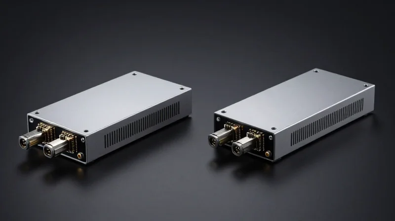
The choice between 800G OSFP DR8, 2xFR4, and 2xDR4 depends primarily on existing fiber infrastructure and the required reach for spine-leaf connections. While DR8 leverages eight parallel lanes of 100G PAM4 to provide the simplest and most cost-effective path for short-reach 500m applications, 2xFR4 utilizes wavelength division multiplexing (WDM) to transmit over fewer fibers at longer distances up to 2km, and 2xDR4 provides a critical migration path for backward compatibility with 400G infrastructure.
Technical Specification Comparison
| Feature | 800G OSFP DR8 | 800G OSFP 2xFR4 | 800G OSFP 2xDR4 |
|---|---|---|---|
| Max Reach | 500m | 2km | 500m |
| Fiber Type | Parallel SMF (16 fibers) | Duplex SMF (4 fibers) | Parallel SMF (16 fibers) |
| Connector Type | MPO-16 / Dual MPO-12 | Dual LC | Dual MPO-12 |
| Optical Technology | 8x100G Parallel | 2x(4x100G) WDM | 2x(4x100G) Parallel |
| Breakout Mode | 8x100G DR / 2x400G DR4 | 2x400G FR4 | 2x400G DR4 |
Strategic Deployment: Parallel Fiber vs. WDM
The 800G OSFP DR8 is the preferred architecture for hyperscale data centers that have already invested in high-count MPO cabling. Because DR8 does not require complex internal multiplexing or demultiplexing components, it typically offers lower power consumption and lower latency compared to WDM-based modules like the 2xFR4. However, the 2xFR4 is superior when fiber conservation is the priority; it delivers 800G over far fewer fibers, which significantly reduces cable management complexity for inter-rack connections exceeding the 500-meter threshold where parallel fiber costs become prohibitive.
The Role of 2xDR4 in Migration
The 2xDR4 module acts as a 'bridge' technology for legacy environments. It is essentially two 400G DR4 engines housed inside a single 800G form factor. This allows operators to split an 800G port directly into two 400G DR4 links using standard MPO-12 connectors. This provides a seamless migration path for the massive installed base of 400G hardware without requiring the specialized MPO-16 cabling or complex breakout panels often associated with native 8x100G DR8 configurations.
Comparison FAQ
- Can 800G DR8 connect directly to 800G 2xFR4?
No. DR8 uses parallel single-mode fiber with 8 distinct channels at 1310nm, while 2xFR4 uses wavelength division multiplexing (CWDM4) over duplex fiber. They are optically incompatible. - Which module is more cost-effective for short distances?
The 800G DR8 is generally more cost-effective for distances under 500m because it uses a simpler uncooled laser design and lacks the expensive MUX/DEMUX optical components required for WDM. - Does 800G DR8 support 400G breakout?
Yes, 800G DR8 can be broken out into 2x400G DR4 or 8x100G DR1 links, providing high flexibility for connecting different switch generations.
Deployment Scenarios in Hyperscale Data Centers

The 800G OSFP DR8 module is a cornerstone of next-generation hyperscale networking, providing the raw throughput and port density required to sustain AI/ML training clusters and massive cloud-scale infrastructures. By leveraging eight parallel lanes of 100G PAM4, these modules offer a unique combination of high-capacity point-to-point connectivity and the flexibility to break down into multiple lower-speed ports, effectively bridging the gap between legacy 100G/400G hardware and the new 800G standard.
Leaf-Spine Interconnects and Topology Scaling
In modern flat-network designs, the 800G OSFP DR8 is primarily utilized as the interconnect between spine switches and leaf switches. Transitioning from 400G to 800G allows data center operators to double their fabric capacity without increasing the number of fiber runs or physical switch ports, which is critical for maintaining a manageable power and cooling profile in high-density environments. The OSFP form factor’s superior thermal management ensures these links remain stable even under the continuous, high-load traffic patterns typical of east-west data flow.
Breakout Scenarios for High-Density Deployments
The parallel architecture of the DR8 interface (8x100G) is its greatest asset for deployment flexibility. Unlike WDM-based modules, the DR8 uses individual fiber pairs for each lane, allowing for simple physical breakouts using MPO-16 or dual MPO-12 cabling systems. This allows a single 800G port to act as multiple logical ports for various network tiers.
| Breakout Mode | Lane Configuration | Connector Type | Primary Use Case |
|---|---|---|---|
| 800G to 8x100G | 8 x 100G-DR | MPO-16 to 8x Duplex LC | Connecting 800G Spine to 100G legacy Leaf/Server ports |
| 800G to 2x400G | 2 x 400G-DR4 | MPO-16 to 2x MPO-12 | Aggregating 400G Leaf switches into an 800G Spine |
| 800G to 1x800G | 1 x 800G-DR8 | MPO-16 to MPO-16 | Direct high-capacity Spine-to-Spine or DCI links |
Support for AI/ML Training Fabrics
AI/ML clusters require massive bandwidth and ultra-low latency for collective communication operations like All-Reduce. The 800G OSFP DR8 is frequently deployed in InfiniBand or high-speed Ethernet backends for GPU-to-GPU clusters. By using DR8 breakout configurations, a single 800G switch can support a higher number of GPU nodes (e.g., via 8x100G breakouts) while maintaining a non-blocking architecture, which is vital for reducing training times in large language models (LLMs).
Deployment FAQ
- Can 800G OSFP DR8 modules interoperate with 400G DR4?
Yes, through a breakout cable, four lanes of an 800G DR8 port can connect directly to a 400G DR4 transceiver, as both use 100G PAM4 modulation per lane over single-mode fiber. - What is the typical reach of DR8 in these scenarios?
The 800G OSFP DR8 is designed for 'Datacenter Reach' (DR), supporting distances up to 500 meters over OS2 single-mode fiber, which covers nearly all intra-datacenter cabling needs. - Why choose DR8 over 2xFR4 for breakouts?
DR8 is preferred for breakouts because it uses parallel fibers (one per lane). 2xFR4 uses wavelength multiplexing, making it significantly more complex and expensive to break out into individual 100G ports.
The 800G OSFP DR8 module is a cornerstone of future-proofed network infrastructure, providing the speed and efficiency required for the AI era. Whether you are scaling a cloud data center or an enterprise AI lab, understanding these specifications is critical for optimal network design. Ready to upgrade your data center interconnects? Contact our technical experts today for a customized consultation or sample evaluation.