Modern campus environments demand unprecedented bandwidth and reliability. As digital transformation accelerates, choosing between fiber-optic backbones and traditional alternatives is no longer just a technical decision—it is a financial and operational imperative. This guide breaks down why fiber is winning the race in performance and cost-efficiency.
The Evolution of Campus Networking Infrastructure
The Era of Copper Constraints
For decades, campus networks relied predominantly on twisted-pair copper cabling, such as Cat5 and Cat6. While these standards were initially sufficient for basic local area networking, they inherently presented physical limitations. The 100-meter distance constraint forced IT administrators to deploy intermediate network closets frequently, increasing the maintenance footprint and power requirements across sprawling campuses. Furthermore, copper infrastructure is susceptible to electromagnetic interference, limiting its efficacy in environments with heavy equipment or high-voltage cabling.
Comparative Performance Metrics
| Feature | Copper (Cat6a) | Fiber Optic |
|---|---|---|
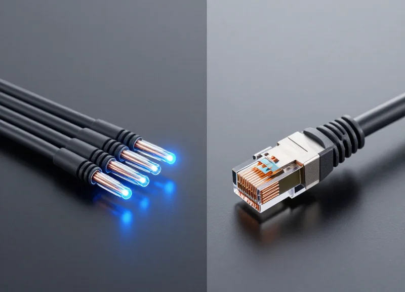
| Max Distance | 100 meters | Up to 40 kilometers |
| Bandwidth Potential | 10 Gbps | 100 Gbps to Terabits |
| Interference | Susceptible | Immune |
| Lifespan | Limited | Future-proof |
Key Drivers of Fiber Adoption
- Scalability Demands
The transition to high-definition video conferencing, IoT devices, and cloud-first educational tools created bandwidth demands that copper simply could not satisfy without massive, expensive infrastructure duplication. - Latency Sensitivity
Modern research and academic applications require near-zero latency, which is achieved through optical transmission rather than electrical signaling used in copper systems. - Inter-Building Connectivity
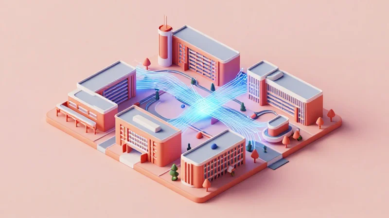
Fiber offers the necessary reach to connect multiple campus buildings on a single broadcast domain, eliminating the need for complex, latency-heavy routing between disparate building segments.
Latency Benchmarks: Why Fiber Wins the Speed Race
The Physics of Speed: Why Fiber Dominates Latency
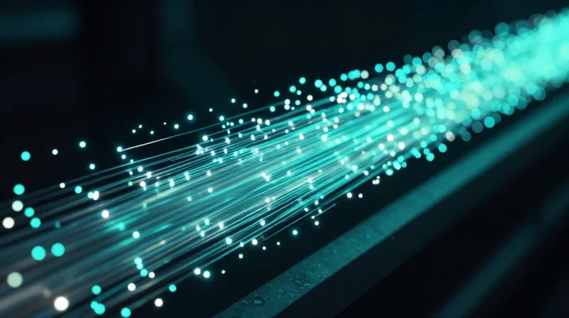
Fiber optic cables transmit data using light pulses through ultra-pure glass, providing a near-perfect medium for data transmission that lacks the electrical resistance and electromagnetic interference found in copper. While the speed of light in glass is approximately 31% slower than in a vacuum, it remains significantly more efficient than electron flow in copper or signal propagation in wireless environments where packet loss and retransmission are common. For campus-wide applications such as high-frequency research data transfers, real-time security monitoring, and institutional ERP systems, the lower latency floor of fiber ensures that the network never becomes the bottleneck for critical operations.
Latency Benchmarks: A Comparative Overview
| Medium Type | Prop. Delay (per km) | Campus RTT (Typical) | Susceptibility to Jitter |
|---|---|---|---|
| Single-Mode Fiber | ~4.9 microseconds | < 1 ms | Negligible |
| Copper (Cat6a/7) | ~5.5 microseconds | 1-5 ms | Moderate (EMI-dependent) |
| Wireless Backhaul | ~3.3 microseconds (Air) | 10-50 ms | High (Weather/Interference) |
| Legacy Coax | ~5.0 microseconds | 10-20 ms | Significant |
Processing Overhead and Signal Degradation
Latency is not merely the time it takes for a signal to travel a physical distance; it also includes the 'processing overhead' at each network node. Copper-based systems require complex signal processing to mitigate crosstalk and attenuation over distances exceeding 100 meters, which adds valuable milliseconds to every packet. Wireless alternatives, while seemingly fast through the air, suffer from protocol overheads like CSMA/CA (Carrier Sense Multiple Access with Collision Avoidance), where devices must wait for a clear channel before transmitting. Fiber eliminates these variables by providing a dedicated, shielded path that requires minimal error correction even at distances of several kilometers.
Performance FAQs: Fiber vs. Alternatives
- Why is 'jitter' often worse on wireless campus networks than fiber?
Jitter is the variance in latency. Wireless networks are susceptible to environmental changes, physical obstacles, and frequency congestion, causing packet delivery times to fluctuate. Fiber provides a stable, fixed path, ensuring consistent timing for voice and video traffic. - Does the 100-meter limit of copper affect campus latency?
Yes. To cover distances beyond 100 meters with copper, you must use repeaters or switches. Every active hop adds switching latency (nanoseconds to microseconds). Fiber can span the entire campus (up to 10km or more) in a single run, removing unnecessary active equipment. - How does fiber improve the performance of cloud-based campus tools?
Cloud applications like Microsoft 365 or Zoom rely on rapid 'handshakes' between the client and server. By reducing the local 'first-mile' latency to near-zero, fiber ensures that the inevitable delays of the public internet are not compounded by a slow local network.
Power Consumption: The Sustainability Advantage of Fiber
Power Consumption: The Sustainability Advantage of Fiber
Fiber-optic connectivity represents a fundamental shift in network sustainability because it utilizes light rather than electrical currents for data transmission. While copper-based Ethernet (Cat6/7) and wireless backhaul require significant power to overcome electrical resistance and signal attenuation over short distances, fiber can carry data for kilometers with negligible signal loss. In a campus environment, this efficiency translates into fewer 'active' components—such as repeaters and signal boosters—directly reducing the aggregate power draw of the networking infrastructure by up to 80% compared to traditional copper architectures.
Passive Optical Networks (PON) vs. Active Architectures
The primary driver behind fiber’s energy advantage is the use of Passive Optical Networking (PON). Unlike active Ethernet, which requires powered switches in telecommunications closets every 100 meters, PON uses unpowered optical splitters to distribute signals. This eliminates the need for 'mid-span' power and, crucially, the climate-controlled environments (HVAC) those active switches would otherwise require. By centralizing active electronics in a single location, campus IT departments can drastically simplify their power distribution and thermal management strategies.
| Network Technology | Power Source Requirement | Estimated Watts per User | Cooling Necessity |
|---|---|---|---|
| Copper (Active Ethernet) | Required at every switch/IDF | 1.5W - 3.0W | High (Requires localized HVAC) |
| Fiber (Passive Optical) | Centralized at Core/OLT | 0.3W - 0.5W | Minimal (Passive splitters) |
| High-Density Wireless | Required at each AP/Node | 5.0W - 12.0W | Moderate (Device dependent) |
Reducing the Carbon Footprint of Campus Data Centers
The environmental impact of fiber extends beyond the cables themselves to the very heart of the campus data center. High-speed fiber allows for the consolidation of hardware, meaning fewer ports and devices are needed to manage the same volume of traffic. This consolidation improves Power Usage Effectiveness (PUE) by reducing the 'idle power' consumed by underutilized equipment. Furthermore, because fiber generates no electromagnetic heat during transmission, the thermal load on server rooms is significantly lower, allowing institutions to meet ESG (Environmental, Social, and Governance) targets by lowering their cooling-related greenhouse gas emissions.
- How does fiber help reduce HVAC costs in old campus buildings?
By replacing powered copper switches with passive splitters, buildings no longer need dedicated cooling systems for wiring closets, often allowing for the decommissioning of localized AC units. - Is fiber manufacturing more sustainable than copper?
Yes. Fiber is made from silica (sand), an abundant resource, whereas copper mining is energy-intensive and involves significant ecological disruption and chemical processing. - Does higher bandwidth on fiber mean higher power consumption?
No. Unlike copper, where higher frequencies require more power to maintain signal integrity, fiber can scale from 1Gbps to 100Gbps with minimal changes in energy consumption per bit of data transferred.
Copper vs. Fiber: Distance and Signal Integrity Limits
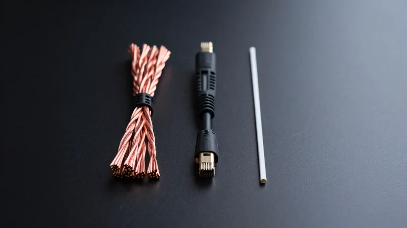
The fundamental divide between copper and fiber optics lies in their transmission medium: copper is limited by the physical resistance of electrical signals over distance, typically capping at 100 meters for high-speed data, whereas fiber optics utilize light pulses that maintain integrity over several kilometers with minimal degradation.
The 100-Meter Barrier: Understanding Copper's Constraints
Copper cabling, such as Cat6a or Cat7, transmits data through electrical voltages. As these electrons move through the wire, they encounter resistance, which converts signal energy into heat. This phenomenon, known as attenuation, causes the signal wave to flatten and lose clarity. Beyond the industry-standard 100-meter limit, the 'Signal-to-Noise Ratio' (SNR) drops to a level where data becomes unrecoverable without active regeneration. Additionally, copper acts as an antenna, picking up Electromagnetic Interference (EMI) and Radio Frequency Interference (RFI) from power lines, machinery, and lighting, further compromising signal integrity in dense campus settings.
Fiber's Optical Advantage: Distance and Purity
Fiber optic cables utilize glass or plastic strands to transmit data as pulses of light. Since light does not experience electrical resistance, attenuation is significantly lower—often measured in decibels per kilometer rather than per meter. Furthermore, because glass is an insulator, it is entirely immune to EMI and RFI. This allows fiber to be run alongside high-voltage power lines or through areas with heavy industrial equipment without any risk of data corruption or cross-talk, making it the only viable solution for connecting disparate buildings across a large campus geography.
| Feature | Copper (Cat6a/7) | Multi-Mode Fiber (OM4) | Single-Mode Fiber (OS2) |
|---|---|---|---|
| Max Distance (10Gbps) | 100 Meters | 400 Meters | 10 - 40 Kilometers |
| EMI/RFI Immunity | Poor (Susceptible) | Total (Immune) | Total (Immune) |
| Signal Loss (Attenuation) | High | Medium-Low | Extremely Low |
| Typical Campus Use | Horizontal (Desks) | Vertical (Risers) | Outside Plant (Backbone) |
Frequently Asked Questions
- Can copper be used for building-to-building links?
While technically possible if the distance is under 100 meters, it is discouraged due to ground potential differences and lightning strike risks, which can damage hardware. Fiber provides electrical isolation, making it safer for inter-building links. - Does weather affect fiber signal integrity?
No. Unlike copper, which can be affected by temperature-induced resistance changes or moisture in connectors, fiber signals are light-based and unaffected by standard environmental temperature fluctuations. - What is the primary limit of fiber distance?
For single-mode fiber, the limit is typically defined by the 'optical budget'—the strength of the laser transmitter versus the sensitivity of the receiver—rather than the cable itself.
Wireless Backhaul vs. Dedicated Fiber: Reliability Comparison
The fundamental difference in reliability between dedicated fiber and wireless backhaul lies in the medium: fiber optics utilize a physical, shielded conduit that is immune to electromagnetic interference and weather, while wireless backhaul relies on atmospheric propagation which is inherently susceptible to signal degradation, weather patterns, and environmental obstructions. For campus environments requiring Five Nines (99.999%) uptime, dedicated fiber remains the only solution that guarantees consistent throughput regardless of external conditions.
Environmental Resilience and Signal Integrity
Dedicated fiber optics are buried or housed in protective conduits, making them virtually immune to atmospheric conditions such as heavy rain, fog, or snow—phenomena known collectively as 'rain fade' in the wireless world. In contrast, high-frequency wireless backhaul (such as 60GHz or 80GHz millimeter-wave) can experience significant signal attenuation during storm events, leading to packet loss or complete link failure. Furthermore, fiber is non-conductive, protecting network equipment from lightning strikes and electrical surges that frequently plague outdoor wireless hardware.
Spectral Congestion and Interference
Wireless backhaul operates in a shared medium. Even licensed bands can face interference from neighboring networks, while unlicensed bands (2.4GHz, 5GHz, 60GHz) are subject to unpredictable noise from other campus devices. Fiber optics, however, offer a closed-loop system where each strand provides dedicated bandwidth. There is zero risk of 'cross-talk' or signal collision from external sources, ensuring that the latency and jitter profiles remain flat even as the surrounding RF environment becomes increasingly crowded.
| Metric | Dedicated Fiber Optics | High-Capacity Wireless Backhaul |
|---|---|---|
| Uptime Guarantee | 99.999% (Carrier Grade) | 99.9% to 99.99% (Weather Dependent) |
| Weather Sensitivity | None (Immune to Rain/Fog) | High (Subject to Rain Fade) |
| Interference Risk | Zero (Physical Shielding) | Moderate to High (RF Congestion) |
| Latency Stability | Sub-millisecond (Deterministic) | Variable (Fluctuates with Link Quality) |
| Security | High (Physical Access Required) | Moderate (Encryption Required for Over-the-Air) |
Reliability FAQ
- Does rain significantly impact campus fiber performance?
No. Because fiber uses light pulses within a glass core protected by multiple layers of cladding and jacketing, atmospheric moisture has zero impact on signal integrity or speed. - What is 'Fresnel Zone' encroachment in wireless backhaul?
The Fresnel Zone is an elliptical area around the line-of-sight path between two wireless points. If trees grow or new buildings are constructed within this zone, signal reliability can drop significantly, a problem that does not exist for underground or correctly routed fiber. - Can wireless backhaul ever match fiber for mission-critical apps?
While modern E-Band wireless can offer multi-gigabit speeds, it cannot match fiber's consistency. For applications like real-time medical imaging or synchronized data center replication, the jitter introduced by wireless environmental variables is often unacceptable.
Total Cost of Ownership (TCO): Beyond the Initial CapEx
The Strategic Shift from CapEx to OpEx in Campus Networking
Assessing the true value of campus fiber connectivity requires looking past the initial capital expenditure (CapEx) to the total cost of ownership (TCO) over a 10- to 20-year horizon. While copper or wireless systems may appear cheaper during the installation phase, they suffer from higher operational expenses (OpEx) due to frequent hardware refreshes, higher energy requirements for active equipment, and susceptibility to environmental degradation. Fiber optics, specifically Passive Optical Networks (PON), minimize the need for mid-span active electronics, thereby slashing cooling and power costs while providing a future-proof foundation that scales with software rather than hardware swaps.
Lifecycle and Replacement Cycles
One of the most significant TCO drivers is the physical lifespan of the medium. Fiber optic cabling is rated for 30 to 50 years, whereas Category 6a or 7 copper cabling often requires replacement within 10 to 15 years to keep pace with bandwidth demands or due to physical oxidation. Wireless backhaul hardware typically hits technical obsolescence every 5 to 7 years. When factoring in the labor costs of repeated cable pulls and hardware decommissioning, fiber’s 'once-and-done' installation model becomes a major financial asset, protecting the institution from the inflationary costs of future labor-intensive retrofits.
| Cost Factor | Fiber Optic | Copper (CAT6a/7) | Wireless Backhaul |
|---|---|---|---|
| Installation (CapEx) | High | Moderate | Low to Moderate |
| Cable Lifespan | 30-50 Years | 10-15 Years | N/A (Hardware 5-7y) |
| Energy Consumption | Very Low (Passive) | High (Active) | Moderate |
| Maintenance (OpEx) | Low | Moderate/High | High (Interference) |
| Scalability Cost | Minimal (SFP Swap) | High (New Runs) | Moderate (New Radio) |
Energy Efficiency and Maintenance Savings
Fiber networks, particularly GPON or EPON architectures, significantly reduce the number of powered switches required across a campus. By eliminating intermediate telecommunications rooms that require dedicated HVAC and backup power, institutions can realize up to a 40% reduction in annual energy costs. Maintenance is further simplified because glass is immune to electromagnetic interference (EMI) and lightning strikes, which are common causes of port failure in copper-based and wireless systems. This inherent reliability translates to fewer service tickets and reduced technician man-hours over the network's life.
Frequently Asked Questions: Fiber TCO
- Is fiber more expensive to repair if a line is cut?
While the tools for fiber splicing are specialized, the frequency of repairs is significantly lower than copper due to fiber's higher tensile strength and immunity to environmental corrosion. - How does fiber impact the real estate value of a campus?
Modern fiber infrastructure is increasingly viewed as a utility-grade asset, increasing the desirability and valuation of campus facilities for high-tech tenants or research departments. - Can existing conduits be reused for fiber to lower costs?
Yes, fiber's small diameter often allows it to be blown through existing congested conduits where bulky copper bundles would not fit, significantly reducing civil engineering costs.
Future-Proofing: Scalability for 5G, IoT, and AI
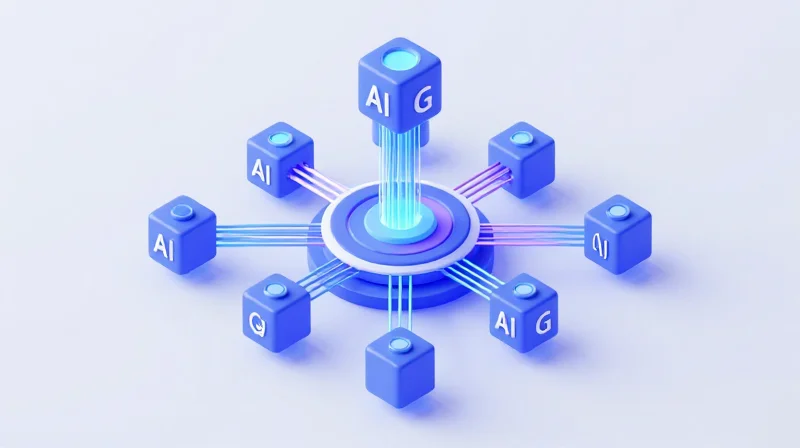
Future-Proofing: Scalability for 5G, IoT, and AI
Fiber optic connectivity is the only transmission medium capable of sustaining the exponential growth of campus data traffic because it decouples the physical infrastructure from bandwidth limitations. While copper and wireless alternatives are bound by rigid physical laws regarding frequency and distance, fiber's capacity is determined by the electronics at either end; by simply upgrading transceivers, a single fiber pair can jump from 10 Gbps to 400 Gbps or more. This inherent scalability makes it the indispensable backbone for the next generation of campus technologies, ensuring that the network can evolve alongside emerging standards without the need for disruptive and costly cable replacements.
Enabling 5G Densification and Small Cell Architecture
The rollout of private 5G on campuses relies heavily on a strategy known as 'densification,' which requires a high number of small cell antennas distributed throughout the environment. Each of these nodes requires a high-capacity backhaul connection to maintain 5G’s promised speeds and ultra-low latency. Wireless backhaul often suffers from interference and line-of-sight issues in dense campus environments, whereas fiber provides a dedicated, interference-free path. This 'fiber-to-the-antenna' approach is the only way to ensure that 5G services—such as augmented reality (AR) for education or remote campus security—function with the necessary reliability.
Infrastructure Readiness Comparison
| Feature | Fiber Optics (Single Mode) | Copper (Cat 6A/7) | Wireless (WiFi 6E/7) |
|---|---|---|---|
| Theoretical Bandwidth | 69 Tbps (and growing) | 10 Gbps | 9.6 - 46 Gbps (Shared) |
| Latency Performance | Lowest (Speed of Light) | Moderate (Distance Sensitive) | Variable (Congestion Sensitive) |
| Lifespan | 25+ Years | 5-10 Years | 3-5 Years (Hardware Cycle) |
| IoT Density Support | Unlimited (via WDM) | Limited by Port Density | Limited by Spectrum Noise |
The Nexus of AI and Edge Computing
Artificial Intelligence applications on campus, from autonomous vehicles to real-time research data processing, generate massive datasets that must be processed at the 'edge' to avoid latency. Fiber supports the high-speed interconnects required between localized edge data centers and the campus core. Using Wave Division Multiplexing (WDM), campuses can run multiple virtual 'lanes' of data over a single fiber strand, allowing AI workloads to operate in isolation from general student traffic. This ensures that mission-critical AI operations never compete for bandwidth with everyday administrative or recreational data usage.
Future-Proofing FAQ
- Can current WiFi 7 technology replace the need for a fiber backbone?
No. While WiFi 7 increases wireless speeds, it requires a robust fiber backhaul to the access point to deliver those speeds to the network core. Without fiber, the access point becomes a bottleneck. - Is fiber worth the investment for a campus with minimal IoT today?
Yes. The cost of retrofitting a campus with fiber after buildings are completed is significantly higher than installing it during initial phases. Fiber provides the 'headroom' for the inevitable influx of smart building sensors and security devices. - How does fiber handle the power requirements of future devices?
While fiber doesn't carry electricity, hybrid 'Powered Fiber' cables combine glass strands with copper conductors, allowing campuses to provide both high-speed data and power to remote IoT devices over distances far exceeding standard PoE limits.
Strategic Deployment: Transitioning from Legacy Systems
Transitioning to campus fiber connectivity from legacy copper or microwave systems is a multi-year strategic initiative that demands a 'backbone-out' approach. Rather than an immediate rip-and-replace, IT leaders should focus on a hybrid architecture that leverages existing infrastructure while systematically eliminating bandwidth bottlenecks. This ensures that the campus can support the exponential growth of AI and IoT applications without causing massive service interruptions during the installation phase.
The Three-Phase Migration Roadmap
A structured migration allows for budgetary flexibility and technical validation. The following phases represent the industry standard for modernizing campus environments.
- Phase 1: Core Backbone Modernization
Upgrade the primary links between data centers and main distribution frames (MDFs) to 100G+ fiber. This eliminates the 'choke point' at the center of the network. - Phase 2: Edge Distribution Expansion
Extend fiber to individual buildings and intermediate distribution frames (IDFs), replacing aging copper trunks with Single-Mode Fiber (SMF) to support greater distances. - Phase 3: Deep Fiber Integration
The final stage involves bringing fiber closer to the end-user or high-demand nodes, such as 5G small cells, high-density lecture halls, and research labs.
Comparison: Legacy vs. Fiber-Ready Architectures
| Feature | Legacy (Copper/Wireless) | Fiber-Ready (GPON/Active Ethernet) | |||
|---|---|---|---|---|---|
| Distance Limits | 100m for Copper | Up to 40km without repeaters | |||
| Maintenance | High (Susceptible to corrosion/EMI) | Low (Resistant to environmental factors) | Power Consumption | High (Requires active cooling for many switches) | Low (Passive optical components require no power) |
| Upgrade Path | Requires new cabling | Change optics only (keep existing fiber) |
Strategic Technical Considerations
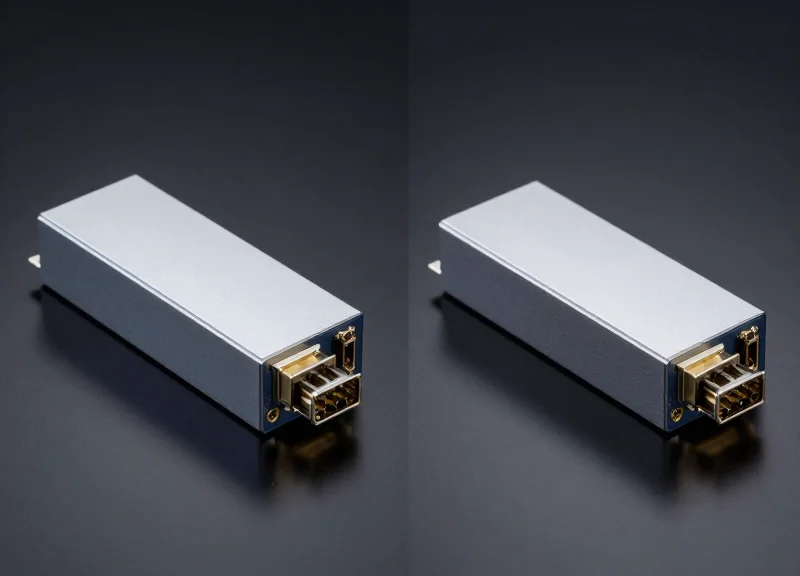
To ensure a seamless transition, IT departments must address the technical bridge between old and new. This often involves the use of high-density media converters and multi-rate SFP+ transceivers that allow 1G, 10G, and 40G equipment to coexist on the same fiber strand during the transition period. Furthermore, auditing existing conduit space is essential; if conduits are at capacity, utilizing micro-fiber and air-blown fiber technology can provide a cost-effective alternative to new trenching.
Migration FAQ
- How do we handle legacy devices that only have copper ports?
Utilize Industrial Media Converters or Layer 2/3 switches with a mix of RJ45 and SFP+ ports to bridge the gap between fiber backhaul and legacy end-point devices. - Can we reuse existing conduits for fiber installation?
Yes, provided the conduit integrity is verified. Micro-trenching or utilizing the 'innerduct' method can allow multiple fiber cables to inhabit the same space previously occupied by a single copper bundle. - What is the most common mistake during fiber deployment?
Underestimating future capacity needs. Installing Multi-Mode fiber (MMF) instead of Single-Mode fiber (SMF) for long runs often leads to expensive re-cabling as speeds move toward 400G.
Transitioning to a fiber-centric campus is a strategic move that pays dividends in performance and sustainability. Ready to upgrade your infrastructure? Contact our engineering team today for a customized TCO audit and start building a future-ready network.