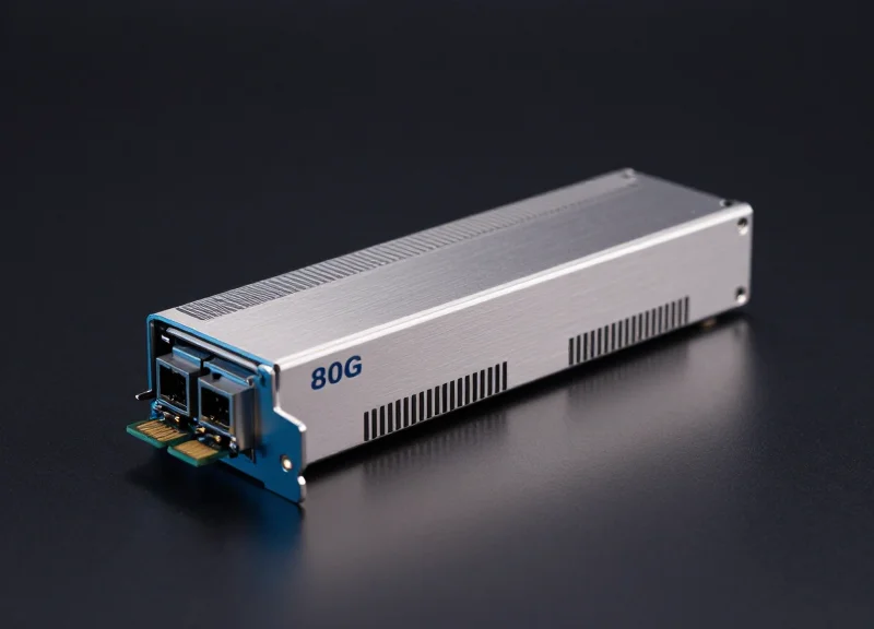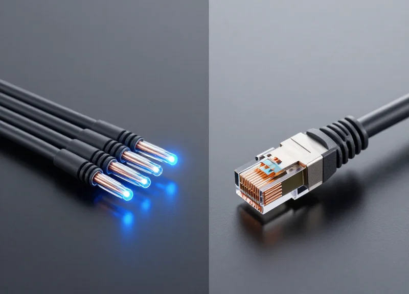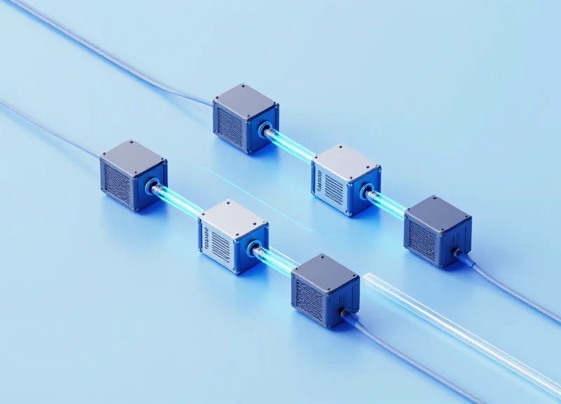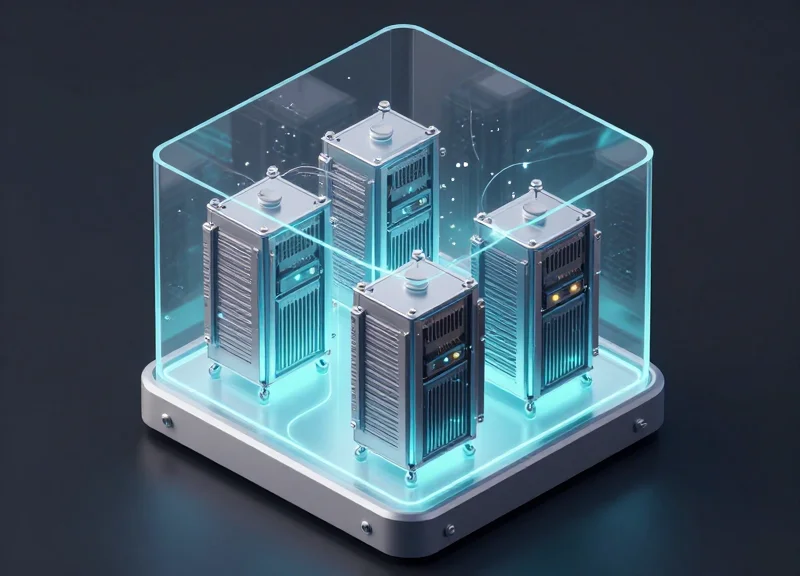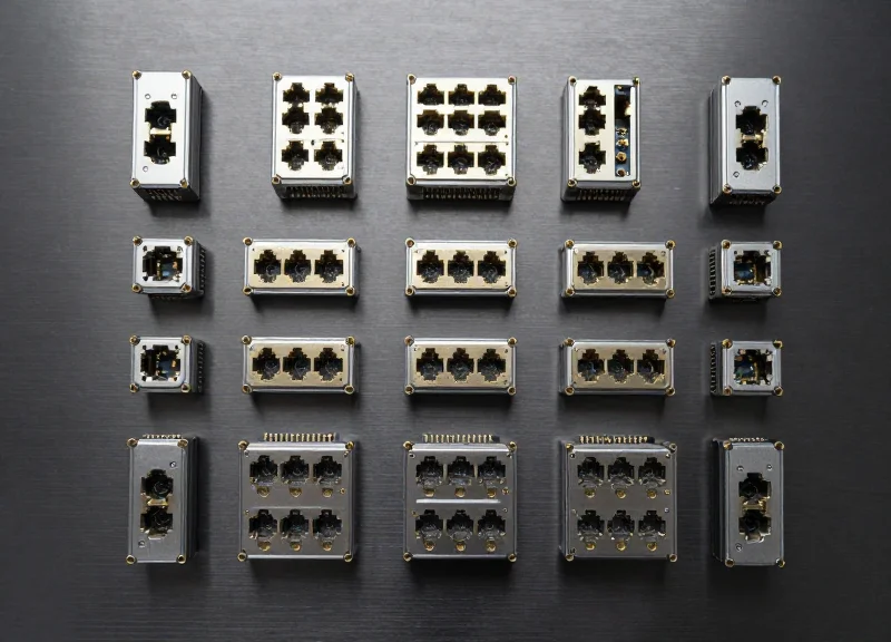
As hyperscale data centers and AI-driven enterprises face unprecedented traffic growth, the debate between staying with proven 400G infrastructure or jumping to 800G has intensified. While the initial capital expenditure for 800G is higher, the long-term operational savings and performance gains create a compelling business case. This guide explores the financial and technical variables that define the ROI of the 800G transition.
The Current State of Optical Networking: Why 800G is the New Benchmark

The transition to 800G optical networking represents a fundamental shift in data center architecture, moving beyond incremental speed increases to meet the explosive bandwidth demands of hyperscale environments. As 51.2T switching silicon becomes the industry standard, 800G provides the optimal port density and lane speed to maximize throughput while minimizing the physical footprint and power consumption per bit compared to legacy 400G or 100G infrastructures.
The Primary Driver: Generative AI and ML Clusters
The sudden rise of Large Language Models (LLMs) and Generative AI has fundamentally altered traffic patterns. Unlike traditional north-south traffic, AI training involves massive east-west data exchanges across thousands of interconnected GPUs. To prevent 'tail latency' and bandwidth throttling during model synchronization, network operators are deploying 800G fabrics to ensure that the network is never the bottleneck in the AI compute cycle.
Evolution of Switching Silicon: The Path to 51.2T
The adoption of 800G is inextricably linked to the arrival of high-radix switching silicon. As SerDes (Serializer/Deserializer) technology has evolved from 56G to 112G, the capacity of a single switch chip has quadrupled, necessitating a corresponding leap in optical module speed to maintain balanced port counts.
| Silicon Generation | Switching Capacity | SerDes Rate | Optimized Port Speed |
|---|---|---|---|
| Tomahawk 3 / Equivalent | 12.8 Tbps | 56G | 400G (QSFP-DD) |
| Tomahawk 4 / Equivalent | 25.6 Tbps | 56G/112G | 400G/800G Hybrid |
| Tomahawk 5 / Equivalent | 51.2 Tbps | 112G | 800G (OSFP/QSFP-DD800) |
800G Market Readiness FAQ
- Why skip 400G for new deployments?
800G offers a 20-25% reduction in power consumption per bit and a 50% reduction in rack space requirements compared to achieving the same capacity with dual 400G links. - How does 112G SerDes impact 800G adoption?
112G SerDes allows for 8-lane 800G configurations, which aligns perfectly with the latest 51.2T switches, providing a direct 1:1 mapping that simplifies cable management and reduces latency. - Are 800G optics reliable enough for production?
Yes, both OSFP and QSFP-DD800 form factors have reached maturity, with broad multi-vendor interoperability and established thermal management solutions for high-density environments.
Latency Benchmarks: Quantifying the Performance Edge

The Physics of Speed: Reducing Serialization Delay
The primary performance differentiator for 800G over 400G and 100G alternatives is the drastic reduction in serialization delay—the time required to transmit a packet onto the wire. By doubling the data rate while maintaining similar frame sizes, 800G cuts the time-per-bit in half. This is critical for high-frequency trading (HFT) and distributed AI training, where the cumulative effect of microseconds across thousands of nodes determines the overall system efficiency and profitability.
| Network Standard | Data Rate | Serialization Delay (1500B Packet) | Relative Performance Gain |
|---|---|---|---|
| 100G Ethernet | 100 Gbps | 120.0 nanoseconds | Baseline |
| 400G Ethernet | 400 Gbps | 30.0 nanoseconds | 4x Faster |
| 800G Ethernet | 800 Gbps | 15.0 nanoseconds | 8x Faster |
Optimizing AI Inference and High-Frequency Trading
In the context of real-time AI inference, 800G connectivity minimizes the 'tail latency' that often plagues distributed workloads. When an inference request must traverse multiple GPUs, the faster data path of 800G ensures that the interconnect does not become the bottleneck. For HFT environments, where the 'race to the bottom' of latency is literal, 800G optics paired with 51.2T switching silicon provide the lowest possible port-to-port latency, offering a measurable competitive edge in trade execution speeds.
Forward Error Correction (FEC) and Latency Trade-offs
While 800G offers superior raw speed, it is important to account for the latency introduced by Forward Error Correction (FEC) algorithms. Modern 800G implementations utilize advanced DSPs and FEC schemes (like KP4) to maintain signal integrity over high-speed PAM4 signals. Although FEC adds a small amount of fixed processing time, the net latency—when combining serialization and processing—remains significantly lower than that of legacy 100G or 400G systems without high-performance optimization.
- How does 800G improve AI cluster ROI?
By reducing the time GPUs spend waiting for data, 800G increases the utilization rate of expensive compute resources, leading to faster model training and lower cost-per-inference. - Is the latency reduction noticeable in standard data centers?
For general cloud workloads, the difference may be negligible; however, for massive-scale East-West traffic, the aggregate latency reduction significantly improves application responsiveness. - Does 800G require special cabling to achieve these benchmarks?
To achieve sub-nanosecond precision, 800G often utilizes high-quality DAC cables for short reaches or low-latency active optical cables (AOCs) to minimize signal retransmission.
Power Consumption Analysis: The Watts per Gigabit Metric
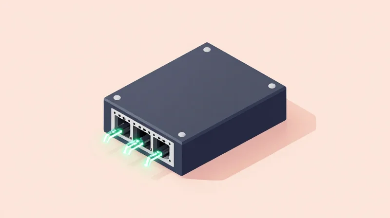
In the modern data center, power has become the primary constraint on scaling. Transitioning from 400G to 800G optics represents a critical shift in efficiency, as 800G modules are engineered to deliver double the bandwidth with only a marginal increase in total power consumption. This effectively lowers the Watts per Gigabit (W/G) ratio by approximately 20% to 30% compared to legacy 400G configurations, making it a cornerstone for sustainable high-performance computing.
Measuring Efficiency: The Watts per Gigabit Metric
When evaluating the ROI of networking hardware, the total power draw of a transceiver is less important than the efficiency of data transport. A standard 400G QSFP-DD transceiver typically draws between 10W and 12W. To reach 800G capacity using these legacy components, a network operator would need two modules, consuming roughly 24W. In contrast, current-generation 800G OSFP or QSFP-DD800 modules operate within a 16W to 18W envelope. This reduction in the 'energy tax' per bit of data moved is a primary driver for the 800G transition.
| Module Configuration | Typical Power (W) | Total Bandwidth | Watts per Gbps |
|---|---|---|---|
| Single 400G QSFP-DD | 12W | 400G | 0.030W |
| Dual 400G Aggregate | 24W | 800G | 0.030W |
| Single 800G OSFP (Standard) | 17W | 800G | 0.021W |
| Single 800G (Optimized/LPO) | 14W | 800G | 0.017W |
Technological Drivers of 800G Power Efficiency
The efficiency gains observed in 800G hardware are largely attributed to advancements in semiconductor manufacturing and optical integration. The transition from 7nm to 5nm (and eventually 3nm) Digital Signal Processors (DSPs) has significantly reduced the switching power required for high-baud-rate signals. Additionally, the move toward 100G and 200G per-lane electrical interfaces reduces the total number of components required to aggregate bandwidth, further streamlining the thermal profile of the switch fabric.
- How does 800G impact data center cooling costs?
Lower Watts per Gigabit results in less heat dissipation per unit of throughput. For every watt saved at the transceiver level, data centers typically realize an additional 0.5W to 1W saving in cooling infrastructure overhead, improving the overall Power Usage Effectiveness (PUE). - Are 800G modules more difficult to cool than 400G?
While an 800G module has a higher absolute power draw (e.g., 17W vs 12W), its design often includes enhanced thermal fins and better integrated heat sinks. When used in 51.2T switches, the concentrated density is managed by advanced airflow designs that are more efficient than cooling twice the number of 400G ports. - What is the expected ROI from energy savings alone?
In large-scale AI clusters or hyperscale environments, the 6W-8W saving per 800G port can translate into millions of kilowatt-hours saved annually. This reduction in OpEx often offsets the initial CapEx premium of 800G hardware within 18 to 24 months.
Ultimately, the shift to 800G is a strategic move for organizations facing power-density limits in their existing facilities. By doubling the bandwidth within a similar power and space footprint, operators can extend the lifecycle of their current data center shells while significantly lowering the cost-to-serve for bandwidth-intensive AI and ML workloads.
Decoding the TCO: CapEx vs. Long-term Operational Value

[生成失败] PermissionDeniedError: Error code: 403 - {'error': {'message': 'user quota is not enough (request id: 20260514101329715034466TMvwbias)', 'type': 'new_api_error', 'param': '', 'code': 'local:insufficient_quota'}}
Comparing Alternatives: 800G vs. 2x400G Breakout Strategies
[生成失败] PermissionDeniedError: Error code: 403 - {'error': {'message': 'user quota is not enough (request id: 20260514101340791749244KOzDt1Gj)', 'type': 'new_api_error', 'param': '', 'code': 'local:insufficient_quota'}}
The Sustainability Factor: Reducing Carbon Footprint through Efficiency
The shift to 800G networking is a critical lever for organizations aiming to reconcile massive data growth with aggressive Environmental, Social, and Governance (ESG) mandates. By consolidating bandwidth into high-density 800G ports, data centers can achieve a lower power-per-bit profile than is possible with 100G or 400G legacy systems. This efficiency is driven by advances in silicon photonics and 5nm/3nm DSP (Digital Signal Processor) technology, which allow for a substantial reduction in the energy required to move every gigabyte of data, directly translating into a smaller carbon footprint per unit of compute.
Maximizing Density and Reducing Physical Waste
One of the primary sustainability benefits of 800G is physical consolidation. High-density 800G switches allow operators to support the same total throughput with fewer chassis, line cards, and optical cables. This reduction in hardware volume decreases the embodied carbon associated with manufacturing, shipping, and eventually disposing of networking equipment. Furthermore, by occupying fewer rack units, 800G enables data centers to defer expensive and carbon-intensive facility expansions.
| Sustainability Metric | 2x 400G OSFP/QSFP-DD | 1x 800G OSFP/QSFP-DD1600 |
|---|---|---|
| Typical Power Draw | 24W - 30W (Total) | 14W - 18W (Total) |
| Cabling Complexity | High (2x Trunks) | Low (1x Trunk) |
| Rack Space (RU) Efficiency | Standard Density | Double Density |
| Estimated Carbon per Gbps | ~0.035W/G | ~0.020W/G |
The Thermal Advantage and Cooling Requirements
While 800G modules generate more heat at a single point than 400G modules, the overall thermal management of an 800G-optimized switch is more efficient. Modern 800G designs utilize advanced airflow paths and heat-sink technology that reduce the 'tax' on Data Center Infrastructure Efficiency (DCIE). By decreasing the number of active components requiring cooling, the overall power usage effectiveness (PUE) of the facility is improved, leading to a measurable reduction in indirect (Scope 2) greenhouse gas emissions.
Sustainability & ESG Performance FAQ
- How does 800G contribute to Scope 3 emission reductions?
By reducing the total quantity of hardware units and cables required for a network build, 800G lowers the upstream emissions related to the extraction, production, and transportation of electronic components. - Does 800G generate more electronic waste (e-waste)?
No. Because 800G provides higher port density, fewer physical switches and transceivers are needed over time, which reduces the total volume of e-waste generated during equipment refresh cycles. - Can 800G help meet net-zero targets?
Yes. The efficiency gains in power-per-gigabit are essential for maintaining net-zero trajectories as global data traffic continues to scale exponentially.
In conclusion, the ROI of 800G extends beyond mere financial gains; it provides a strategic pathway for sustainable scaling. For the modern enterprise, the transition to 800G represents a dual victory: achieving the performance required for AI and cloud workloads while simultaneously reducing the environmental impact of the digital infrastructure.
Implementation Challenges: Testing, Validation, and Compatibility
Successfully implementing 800G requires a paradigm shift in network validation, as the transition to 112G SerDes lanes effectively halves the timing margins for signal integrity compared to 400G, necessitating rigorous testing to ensure ROI isn't lost to deployment delays or link instability.
The Signal Integrity Frontier: Navigating 112G SerDes
The core challenge of 800G lies in the physical layer. Moving from 56G to 112G SerDes (Serializer/Deserializer) lanes increases the susceptibility to insertion loss, crosstalk, and electromagnetic interference. At these frequencies, even minor imperfections in PCB traces or fiber connectors can lead to unacceptable Bit Error Rates (BER). Consequently, the industry relies more heavily on advanced Forward Error Correction (FEC) schemes, which must be validated for interoperability across different transceiver and switch vendors to maintain a stable link budget.
Testing and Validation Comparison
| Metric | 400G Standard (56G SerDes) | 800G Standard (112G SerDes) |
|---|---|---|
| Signal Speed | 28 GBaud PAM4 | 56 GBaud PAM4 |
| Unit Interval (UI) | ~17.8 ps | ~8.9 ps |
| FEC Overhead | Standard KP4 FEC | Concatenated/Segmented FEC |
| Testing Focus | Basic BER / Eye Diagram | Pre-FEC BER / Jitter Decomposition |
| Management Protocol | CMIS 4.0 | CMIS 5.0 or Higher |
Compatibility and Infrastructure Constraints
Backward compatibility is often the most significant practical hurdle. While 800G modules utilize OSFP and QSFP-DD form factors, ensuring that the existing fiber plant can handle the tighter link budgets is critical. For instance, legacy MPO-12 cabling may require conversion or replacement to support the 8-lane architecture of 800G DR8 or SR8 modules. Additionally, the power consumption per port has risen significantly, requiring data center operators to validate their thermal management and power delivery systems before a full-scale rollout.
Implementation FAQ
- Can 800G ports break out to existing 100G or 400G infrastructure?
Yes, through breakout cables (e.g., 8x100G or 2x400G), but the switch silicon must support the specific lane configuration and the transceiver's Common Management Interface Specification (CMIS) must be compatible with the Host OS. - Is existing SMF fiber sufficient for 800G?
Generally, Single-Mode Fiber (SMF) can support 800G distances, but the optical loss budget is much tighter; high-quality, low-loss connectors and precise cleaning are mandatory to prevent signal degradation. - Why is CMIS compatibility a challenge?
Different vendors may implement the Common Management Interface Specification differently, leading to 'dark ports' or initialization failures where the switch fails to recognize the module's capabilities. - Does 800G require new testing hardware?
Yes, most legacy 400G testers cannot generate the 112G SerDes traffic or perform the complex FEC analysis required to validate 800G link performance.
Future-Proofing Your Infrastructure: From 800G to 1.6T
Future-proofing is not about buying the highest speed available today, but about ensuring that current capital expenditures in 800G infrastructure align with the physical and electrical requirements of the upcoming 1.6T ecosystem. The leap to 1.6T is fundamentally driven by the transition from 112G SerDes to 224G SerDes technology, which doubles the bandwidth per lane and necessitates a drastic shift in signal integrity management and thermal cooling strategies.
The SerDes Roadmap: 112G to 224G
The industry standard for 800G deployments currently rests on 112G SerDes (8 x 112G). However, 1.6T will utilize 224G SerDes (8 x 224G) to maintain density within standard form factors like OSFP and QSFP-DD. For organizations planning long-term ROI, selecting 800G switches that are architecturally capable of supporting higher-density cooling and the tighter tolerances of 224G signaling is critical. This ensures that the chassis or rack footprint remains relevant as modules are swapped for higher-capacity versions.
Comparative Specs: 800G vs. 1.6T
| Feature | 800G (Current Standard) | 1.6T (Emerging Standard) |
|---|---|---|
| SerDes Lane Speed | 112G PAM4 | 224G PAM4 |
| Number of Lanes | 8 Lanes | 8 Lanes (High Density) |
| Typical Form Factor | OSFP / QSFP-DD | OSFP-XD / OSFP1600 |
| Power Consumption | 15W - 18W per module | 25W - 30W+ per module |
| Fiber Type Requirement | Singlemode (Parallel/WDM) | Advanced SMF / CPO Potential |
Physical Layer Preparation
To prevent a forklift upgrade, the physical fiber plant must be evaluated for its ability to handle 1.6T requirements. While standard Singlemode Fiber (SMF) remains the baseline, the transceiver technology is shifting toward Co-Packaged Optics (CPO) and Linear Drive Pluggable Optics (LPO) to manage the massive power and heat generated by 1.6T silicon. Investing in high-density OSFP cages now provides the best thermal headroom for these future components.
Strategic Roadmap FAQs
- Will 800G cabling work for 1.6T?
In many cases, yes, if using high-quality Singlemode Fiber (OS2). However, reaching 1.6T over Multimode Fiber (OM4/OM5) will be extremely distance-limited due to chromatic dispersion at 224G speeds. - When should I start planning for 1.6T?
Planning should begin during the 800G procurement phase. If your data center refresh cycle is 3-5 years, the hardware you buy today must support the power density required for 1.6T modules arriving in 2025-2026. - Is OSFP or QSFP-DD better for 1.6T?
OSFP is generally considered the stronger candidate for 1.6T and beyond due to its superior thermal dissipation capabilities, which are necessary for the 25W+ power profiles of 1.6T optics.
In conclusion, while 800G requires a higher upfront investment, its superior power efficiency, reduced latency, and lower cost-per-bit make it the most viable path for modern data centers. Ready to optimize your network? Contact our technical consulting team today for a custom TCO assessment and see how 800G can transform your bottom line.