As global data traffic continues its exponential climb, network architects are under pressure to find long-reach, high-density solutions that don't compromise on efficiency. The 200G QSFP56 ER4 emerges as a pivotal solution for extended reach connectivity up to 40km. This technical deep dive explores the architecture, modulation, and real-world deployment strategies that make this transceiver a cornerstone of modern optical infrastructure.
Introduction to 200G QSFP56 ER4 Architecture
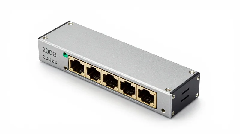
The 200G QSFP56 ER4 is a high-density, hot-pluggable optical transceiver designed for 200 Gigabit Ethernet links over distances up to 40km. It leverages the Quad Small Form-factor Pluggable 56 (QSFP56) design, utilizing four independent 50Gbps lanes modulated with 4-level Pulse Amplitude Modulation (PAM4). By employing a LAN-WDM optical sub-assembly, the ER4 variant multiplexes four specific wavelengths into a single-mode fiber, providing a robust solution for backhaul and metropolitan area networks where extended reach and high spectral efficiency are paramount.
The QSFP56 Form Factor: Performance Evolution
The QSFP56 form factor is the direct evolutionary successor to the QSFP28. While it maintains the same physical dimensions to ensure backwards compatibility with legacy cages in certain hardware configurations, the internal electrical interface is significantly enhanced. The primary differentiator is the shift from 25G NRZ (Non-Return to Zero) signaling used in QSFP28 to 50G PAM4 signaling. This allows the module to double the aggregate bandwidth to 200Gbps without increasing the number of physical lanes or significantly expanding the thermal footprint.
Decoding the ER4 Designation
The 'ER4' nomenclature identifies the specific optical characteristics and reach capabilities of the module. 'ER' stands for Extended Reach, indicating a transmission distance of up to 40km using Single Mode Fiber (SMF) with the assistance of Host Forward Error Correction (FEC). The '4' indicates the use of four distinct optical wavelengths. Unlike SR4 (Short Reach) which uses parallel fiber, the ER4 uses Local Area Network Wavelength Division Multiplexing (LAN-WDM) to grid four lanes onto a single fiber pair.
| Feature | 200G QSFP56 SR4 | 200G QSFP56 FR4 | 200G QSFP56 ER4 |
|---|---|---|---|
| Max Reach | 100m (OM4) | 2km (SMF) | 40km (SMF) |
| Modulation | PAM4 | PAM4 | PAM4 |
| Wavelength | 850nm | CWDM4 Grid | LAN-WDM Grid |
| Optical Interface | MPO-12 | Duplex LC | Duplex LC |
Optical Lane Specifications
The ER4 architecture utilizes the LAN-WDM wavelength grid, which is characterized by narrower spacing than CWDM, allowing for better performance over long distances by minimizing chromatic dispersion. The four wavelengths are centered at 1295.56nm, 1300.05nm, 1304.58nm, and 1309.14nm. These signals are managed by cooled EML (Electro-absorption Modulated Lasers) and high-sensitivity APD (Avalanche Photodiode) receivers to maintain signal integrity over the 40km span.
- Does 200G ER4 require FEC?
Yes, to achieve the full 40km reach, the module relies on the host system to implement KR4 Forward Error Correction (FEC) to mitigate bit errors inherent in high-speed PAM4 transmission over long distances. - Is QSFP56 ER4 backwards compatible with QSFP28?
While the physical form factor is the same, the modulation (PAM4 vs NRZ) is different. A QSFP56 port can often accept a QSFP28 module, but a 200G ER4 module will not function in a legacy 100G QSFP28 port unless the hardware specifically supports 200G PAM4. - What is the typical power consumption?
A 200G QSFP56 ER4 module typically consumes between 5W and 7.5W, depending on the manufacturer and the operating environment, necessitating robust thermal management in high-density switches.
The Shift to PAM4: Doubling Capacity without Doubling Fiber
How PAM4 Redefines Optical Throughput
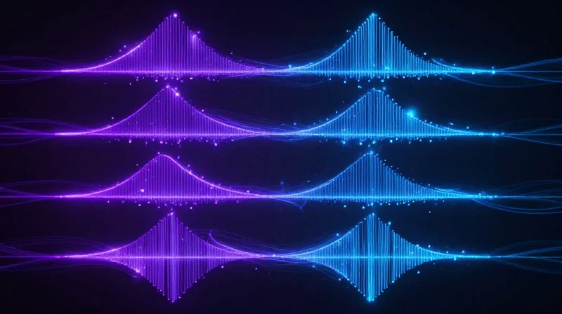
To achieve 200G throughput within the QSFP56 form factor, the industry shifted from traditional Non-Return to Zero (NRZ) signaling to 4-level Pulse Amplitude Modulation (PAM4). While NRZ uses two signal levels to represent a logical 0 or 1, PAM4 utilizes four distinct voltage levels to represent four combinations of two bits: 00, 01, 10, and 11. This transition allows the 200G QSFP56 ER4 to transmit 50Gbps per lane over four wavelengths, reaching the 200G aggregate capacity without requiring a doubling of the physical fiber count or an unsustainable increase in the baud rate.
Technical Comparison: NRZ vs. PAM4
| Feature | NRZ (Binary) | PAM4 (Multilevel) |
|---|---|---|
| Bits per Symbol | 1 bit | 2 bits |
| Signal Levels | 2 levels (0, 1) | 4 levels (0, 1, 2, 3) |
| Baud Rate @ 50G | 50 GBaud | 25-28 GBaud |
| Signal-to-Noise Ratio | High (Better Resilience) | Low (Higher Sensitivity) |
| Bandwidth Efficiency | 1x | 2x |
The Necessity of the Digital Signal Processor (DSP)
The move to PAM4 introduces significant design challenges, primarily because the 'eye diagram' for PAM4 has three openings instead of one. These eyes are smaller, making the signal more susceptible to noise and inter-symbol interference (ISI). To counteract this, the 200G QSFP56 ER4 module incorporates a powerful Digital Signal Processor (DSP). The DSP handles equalization and clock recovery, ensuring that the 4-level signal can be accurately decoded at the receiver side after traversing 40km of single-mode fiber.
Efficiency and Cost Benefits
By doubling the data density per clock cycle, PAM4 reduces the required frequency bandwidth for the optical components. This allows manufacturers to use 25G-class optical components—such as lasers and modulators—to achieve 50G per lane performance. This reuse of established optical technology is critical for maintaining the cost-effectiveness and thermal efficiency of the QSFP56 ER4 module, which must operate within a strict power envelope while delivering high-speed data across extended reaches.
Frequently Asked Questions
- Why does 200G QSFP56 ER4 require Forward Error Correction (FEC)?
Due to the reduced Signal-to-Noise Ratio (SNR) in PAM4 signaling, the probability of bit errors is higher than in NRZ. Host-side FEC (such as KP4 FEC) is mandatory to correct these errors and maintain a reliable link over long distances. - Does PAM4 increase the power consumption of the module?
Yes, the addition of the DSP required for PAM4 processing consumes more power compared to simple NRZ retimers. However, the QSFP56 form factor is specifically designed with improved thermal management to handle this increased load. - Can PAM4 modules interoperate with NRZ modules?
No. PAM4 and NRZ use entirely different modulation formats at the physical layer. A 200G PAM4 port cannot natively communicate with a 100G NRZ port unless a gearbox or specialized translation layer is used.
Technical Specifications: Power, Wavelength, and Sensitivity
Technical Specifications: Power, Wavelength, and Sensitivity
The 200G QSFP56 ER4 optical module is engineered for high-density, long-reach applications, leveraging a sophisticated 4-channel LAN-WDM design and PAM4 modulation to maintain signal integrity over 40km of single-mode fiber (SMF). Its technical profile is defined by tight wavelength spacing and high-sensitivity receivers that compensate for the signal-to-noise ratio challenges inherent in 50Gbps-per-lane PAM4 signaling.
LAN-WDM Wavelength Allocation
The 200G ER4 standard utilizes the Local Area Network Wavelength Division Multiplexing (LAN-WDM) grid. Unlike Coarse WDM (CWDM), LAN-WDM channels are positioned much closer together within the O-band, specifically centered around the zero-dispersion wavelength of G.652 fiber. This precision reduces chromatic dispersion, which is vital for maintaining the temporal alignment of the PAM4 eyes over 40km without the need for external dispersion compensation.
| Channel | Center Wavelength (nm) | Frequency (THz) |
|---|---|---|
| L0 | 1295.56 | 231.4 |
| L1 | 1300.05 | 230.6 |
| L2 | 1304.58 | 229.8 |
| L3 | 1309.14 | 229.0 |
Power Consumption and Thermal Efficiency
The QSFP56 form factor is highly sensitive to thermal performance due to its compact size. The 200G ER4 module typically operates with a maximum power consumption of approximately 7.0W. This power budget includes the high-performance Digital Signal Processor (DSP) required for PAM4 clock and data recovery (CDR) and the thermo-electric cooler (TEC) necessary to stabilize the LAN-WDM lasers. Effective heat dissipation in the switch chassis is critical to ensure the module stays within its standard 0°C to 70°C operating temperature range.
Receiver Sensitivity and Link Budget
Achieving a 40km reach with PAM4 requires significantly higher receiver sensitivity than traditional 10km LR4 modules. The 200G ER4 generally utilizes an APD (Avalanche Photodiode) receiver rather than a PIN diode to enhance sensitivity. Since PAM4 reduces the signal-to-noise ratio (SNR) compared to NRZ, the optical budget must be managed strictly, often requiring a minimum receiver sensitivity in the range of -15 dBm to -17 dBm (depending on the Pre-FEC Bit Error Rate).
| Parameter | Typical Specification |
|---|---|
| Modulation Type | PAM4 |
| Max Transmission Distance | 40km (with Host FEC) |
| Typical Power Consumption | 7.0W |
| Optical Connector | Duplex LC |
| Transmitter Type | EML (Electro-absorption Modulated Laser) |
Technical FAQ: Specs in Detail
- Why is LAN-WDM necessary for 200G ER4?
LAN-WDM provides tighter channel spacing near the zero-dispersion point of single-mode fiber, which is essential for PAM4 signals that are highly susceptible to chromatic dispersion over 40km. - Does the 200G QSFP56 ER4 require FEC?
Yes, the link must operate with Forward Error Correction (FEC) on the host equipment. Specifically, RS(544,514) FEC is required to correct the raw BER to a post-FEC level of < 1E-12. - How does the power consumption compare to 100G ER4?
While 100G ER4 often consumed 3.5W to 5W, the 200G ER4 increases this to roughly 7W due to the complexity of the 50G PAM4 DSPs.
Link Budget Analysis for 40km Transmission
Link Budget Analysis for 40km Transmission
Achieving a 40km reach at 200G speeds necessitates a robust optical link budget that accounts for fiber attenuation, chromatic dispersion, and the signal-to-noise ratio requirements inherent to PAM4 modulation. Unlike 100G ER4 solutions which often used NRZ, the 200G QSFP56 ER4 relies on the combination of higher-order modulation and integrated semiconductor optical amplifiers (SOA) or high-sensitivity APD receivers to bridge the 18dB+ loss typical of 40km spans.
Calculating the Optical Power Budget
The power budget is the difference between the transmitter's output power and the receiver's sensitivity. For 200G ER4, the budget must be strictly maintained to keep the Pre-FEC Bit Error Rate (BER) within the limits that the host system can correct.
| Parameter | Value (Typical) | Unit |
|---|---|---|
| Minimum Launch Power (Per Lane) | +2.0 | dBm |
| Fiber Attenuation (40km @ 0.25dB/km) | 10.0 | dB |
| Connector and Splice Loss | 2.0 | dB |
| Operating Margin | 2.0 | dB |
| Required Receiver Sensitivity (Post-FEC) | <-16.0 | dBm |
The Necessity of Host FEC (KP4)
One of the most critical aspects of 200G QSFP56 ER4 transmission is its dependence on Forward Error Correction (FEC). Unlike older 10km standards that could occasionally run error-free without FEC, the 40km ER4 standard specifically utilizes IEEE 802.3bs KP4 FEC. PAM4 signaling is more susceptible to noise due to its four distinct voltage levels being packed into the same amplitude swing as NRZ. The KP4 FEC algorithm resides on the host IC and is responsible for correcting a raw BER of approximately 2.4E-4 to a post-FEC BER of better than 1E-12, effectively making the long-distance transmission reliable.
- Does 200G ER4 require an external amplifier?
No, the 200G QSFP56 ER4 module typically includes internal amplification or high-sensitivity APD components to reach 40km without requiring external line amplifiers. - What happens if FEC is disabled on the host port?
If FEC is disabled, the link will likely fail or experience massive packet loss, as the raw PAM4 signal over 40km exceeds the error thresholds of standard Ethernet processing. - How does dispersion affect the 40km link?
The LAN-WDM wavelength grid is specifically chosen near the zero-dispersion point of G.652 fiber to minimize chromatic dispersion, ensuring signal pulse integrity over the 40km span.
Thermal Management and Cooling in QSFP56 Systems
Thermal Management and Cooling in QSFP56 Systems
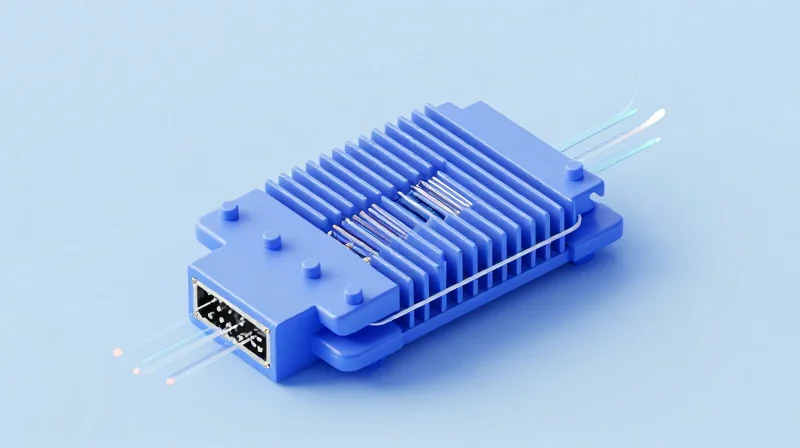
Thermal management in 200G QSFP56 ER4 systems is primarily defined by the challenge of dissipating approximately 7W of power within a compact footprint while maintaining the strict temperature tolerances required for 40km optical transmission. Efficient heat removal is not merely a matter of component longevity; it is a prerequisite for signal integrity, as the 4-level Pulse Amplitude Modulation (PAM4) used in these modules is highly sensitive to thermal noise and laser wavelength instability caused by localized hotspots.
Heat Dissipation Challenges in High-Density Ports
In high-density data center switches, where 32 or more QSFP56 ports may be populated in a single rack unit, the cumulative thermal load can exceed 220W. The ER4 variant is particularly susceptible to thermal issues because its LAN-WDM lasers require precise frequency stability to remain within their designated 800GHz channels. Excessive heat causes 'wavelength drift,' where the laser frequency shifts, leading to increased bit error rates (BER) and potentially triggering Forward Error Correction (FEC) thresholds that degrade link throughput.
| Cooling Component | Primary Function | Optimization Strategy |
|---|---|---|
| Riding Heat Sink | Provides direct conductive cooling for the module shell | Increased fin height and high-velocity airflow integration |
| Thermal Interface Material (TIM) | Reduces air gaps between the module and the heat sink | Use of high-conductivity pads with low compression force |
| Internal Heat Spreaders | Distributes heat from the DSP to the module casing | Nickel-plated copper shells to improve heat flux distribution |
Optimizing Airflow and Heat Sink Integration
System designers must optimize both the passive and active elements of the cooling path. Passive management involves the use of 'riding heat sinks' that maintain physical contact with the top surface of the QSFP56 module via spring-loaded clips. Active management relies on chassis-level airflow, where the pressure drop across the cage must be minimized to allow sufficient air volume to pass over the cooling fins. Engineering the surface roughness of the module's top plate is also critical, as even microscopic air gaps can significantly increase thermal resistance (Rth), leading to premature thermal throttling of the internal Digital Signal Processor (DSP).
- What is the maximum case temperature for a 200G QSFP56 ER4?
The standard commercial operating case temperature range is 0°C to 70°C, beyond which the module may enter a low-power protection mode. - How does PAM4 signaling impact thermal design?
PAM4 requires more sophisticated DSPs compared to NRZ, which increases power consumption by roughly 20-30%, necessitating more aggressive cooling solutions. - Does airflow direction affect ER4 performance?
Yes, front-to-back (port-to-CPU) airflow is generally preferred for optical modules as it ensures the coolest air reaches the transceivers before being heated by other internal components.
Application Scenarios: Data Center Interconnect (DCI)

Application Scenarios: Data Center Interconnect (DCI)
In the evolving landscape of edge computing and distributed cloud services, the 200G QSFP56 ER4 module acts as a critical enabler for Metro Data Center Interconnect (DCI) strategies. It is specifically engineered to bridge the gap between short-reach campus links and long-haul coherent transport, providing a robust 40km reach over standard Single Mode Fiber (SMF) that meets the throughput demands of modern high-bandwidth applications.
Eliminating Optical Amplification in Metro Links
The primary value proposition of the 200G ER4 in DCI environments is the elimination of mid-span infrastructure. Traditionally, reaching distances up to 40km at high data rates required the use of Erbium-Doped Fiber Amplifiers (EDFAs) to boost signal strength or complex coherent transceivers. The 200G QSFP56 ER4 utilizes high-performance EML (Electro-absorption Modulated Laser) transmitters and sensitive APD (Avalanche Photodiode) receivers to achieve a link budget that accommodates 40km of fiber loss natively. This 'passive' approach significantly reduces both Capital Expenditure (CAPEX) and Operational Expenditure (OPEX) by removing the power, cooling, and maintenance requirements of active amplification sites.
| Feature | 200G QSFP56 ER4 | 200G Coherent (QSFP-DD) |
|---|---|---|
| Typical Reach | Up to 40km | 80km to 1000km+ |
| Power Consumption | < 7.5W | 15W - 22W |
| Latency | Ultra-Low (Direct Detection) | Higher (Due to DSP processing) |
| Cost per Port | Economic / Mid-range | High / Premium |
| Infrastructure | Point-to-Point (Passive) | Requires Active DWDM System |
Optimizing Network Latency and Power Efficiency
For DCI applications such as synchronous data replication and storage area network (SAN) extension, latency is a non-negotiable metric. Because the 200G QSFP56 ER4 utilizes direct detection rather than the complex Digital Signal Processing (DSP) required for coherent modulation, it offers significantly lower latency. Furthermore, at approximately 7-7.5W per module, it allows data center operators to maximize port density in high-radix switches without exceeding the thermal envelopes of standard 1RU or 2RU chassis, which is often a limiting factor in metro-edge facilities.
- Can 200G ER4 be used for point-to-multipoint DCI?
No, it is primarily designed for point-to-point 40km links. However, it can be integrated into standard patch panels and cross-connects within a metro fiber ring. - Does this module require special fiber for 40km?
It works over standard G.652 Single Mode Fiber. Performance is optimized when the fiber plant is clean and splices are within standard loss tolerances. - Why choose ER4 over LR4 for DCI?
200G LR4 is limited to 10km. For links between 10km and 40km, ER4 is mandatory to ensure signal integrity without adding external amplifiers.
Telecom Carrier Backhaul and 5G Infrastructure
The Strategic Role of 200G ER4 in 5G Architecture
The 200G QSFP56 ER4 serves as a critical bridge in the 5G evolution, offering service providers a high-capacity, mid-reach solution that satisfies the rigorous bandwidth demands of modern telecom backhaul. As 5G New Radio (NR) deployments scale, the transport network must handle significantly increased data traffic from cell sites to the core. The ER4 variant, with its 40km reach over single-mode fiber (SMF) using PAM4 modulation, allows carriers to consolidate multiple 100G links into a single 200G interface, optimizing fiber utilization and reducing the physical footprint in central offices and hub sites.
Optimizing Midhaul and Backhaul Transport
In 5G networks, the transport layer is divided into fronthaul, midhaul, and backhaul. While fronthaul often relies on shorter-reach optics, the midhaul (connecting the Distributed Unit to the Centralized Unit) and backhaul (connecting the CU to the Core Network) frequently require the 30km to 40km reach provided by ER4 technology. The use of QSFP56 ER4 in these segments eliminates the need for optical amplifiers in many metro-scale deployments, significantly lowering capital expenditure (CAPEX) and simplifying network maintenance.
| Feature | 100G QSFP28 ER4 | 200G QSFP56 ER4 | 400G QSFP-DD ER4 |
|---|---|---|---|
| Modulation | NRZ | PAM4 | PAM4 |
| Maximum Reach | 40km | 40km (with FEC) | 40km (with FEC) |
| Power Consumption | < 5.0W | < 7.5W | < 12.0W |
| Spectral Efficiency | Baseline | 2x Baseline | 4x Baseline |
| Primary Application | 4G/LTE Backhaul | 5G Midhaul/Backhaul | Core Aggregation |
Operational Advantages for Service Providers
- Fiber Conservation
By doubling the capacity per wavelength compared to 100G ER4, carriers can defer expensive new fiber trenching projects by maximizing existing fiber plants. - Power Efficiency
The QSFP56 form factor provides a better 'bits-per-watt' ratio than legacy solutions, which is vital for remote cabinets with limited power and cooling budgets. - Seamless Integration
Because it utilizes the established QSFP form factor, 200G ER4 is backwards compatible with many existing switches and routers, allowing for phased upgrades.
Telecom Deployment FAQ
- Why is FEC mandatory for 200G ER4 in telecom applications?
Unlike older 100G NRZ standards, the PAM4 modulation used in 200G ER4 is more sensitive to noise. Forward Error Correction (FEC) is required on the host equipment to maintain link integrity over the full 40km distance. - Can 200G ER4 be used in environments without climate control?
Most 200G ER4 modules are rated for commercial temperature ranges (0°C to 70°C), but industrial temperature (I-Temp) versions are increasingly available for outdoor cabinet deployments common in telecom networks. - How does 200G ER4 impact latency in 5G networks?
The optical transmission itself adds negligible latency; however, the mandatory host-side FEC adds a few microseconds. This is generally well within the requirements for 5G midhaul and backhaul segments.
Interoperability and Industry Standards Compliance
The Foundation of Interoperability: IEEE and MSA Standards
Interoperability for 200G QSFP56 ER4 transceivers is not a coincidence but the result of rigorous adherence to international protocols that define the optical, electrical, and mechanical boundaries of the hardware. By following the IEEE 802.3bs and Multi-Source Agreement (MSA) specifications, manufacturers ensure that their modules can operate reliably in a heterogeneous network environment. This standardization allows network engineers to deploy 200G ER4 solutions across switches and routers from different vendors, such as Cisco, Arista, and Juniper, without the risk of physical mismatch or signal incompatibility.
IEEE 802.3bs: The 200GBASE-ER4 Optical Specification
The IEEE 802.3bs standard is the primary authority for 200GbE over single-mode fiber. For the ER4 variant, it specifies the 200GBASE-ER4 Physical Medium Dependent (PMD) sublayer. This standard dictates the use of four LAN-WDM wavelengths (1295nm to 1309nm) and the implementation of PAM4 modulation. Crucially, it defines the Bit Error Rate (BER) thresholds and the requirement for host-side KP4 Forward Error Correction (FEC), which is essential for maintaining signal integrity over the 40km span.
QSFP56 MSA and Management Interface Compliance
While IEEE handles the optical transmission, the QSFP56 MSA (Multi-Source Agreement) defines the physical form factor and the electrical interface. This includes the mechanical dimensions of the module, the 38-pin connector layout, and the Common Management Interface Specification (CMIS). Compliance with CMIS is particularly vital for interoperability, as it standardizes how the host system monitors Digital Optical Monitoring (DOM) parameters like laser bias, temperature, and RX power levels.
| Standard Authority | Primary Focus | Impact on 200G ER4 Interoperability |
|---|---|---|
| IEEE 802.3bs | Optical/Link Layer | Defines 200GBASE-ER4 PAM4 signaling and link budget for 40km reach. |
| QSFP56 MSA | Mechanical/Electrical | Ensures physical fit, pin compatibility, and thermal dissipation standards. |
| SFF-8636 / CMIS | Management Interface | Standardizes I2C communication and real-time diagnostic monitoring (DOM). |
| OIF CEI-56G-VSR | Chip-to-Module | Governs the 50G PAM4 electrical lanes between the host ASIC and the module. |
Interoperability and Compatibility FAQ
- Can a 200G QSFP56 ER4 module work in a QSFP-DD port?
Yes. QSFP-DD ports are designed to be backward compatible with QSFP56 modules. The 200G ER4 module will fit mechanically and operate as long as the switch OS supports the 200G configuration. - Is KP4 FEC mandatory for 200G ER4 links?
Yes. Per IEEE 802.3bs, the host system must enable KP4 Forward Error Correction to bridge the gap between the raw BER and the required error-free performance of 1E-12. - Will 200G ER4 interoperate with 200G LR4?
Generally, no. While they share the same wavelengths, ER4 has a much higher launch power and receiver sensitivity designed for 40km, which could saturate or damage a 10km LR4 receiver without significant attenuation.
Comparison: QSFP56 ER4 vs. QSFP-DD and Other 200G Variants
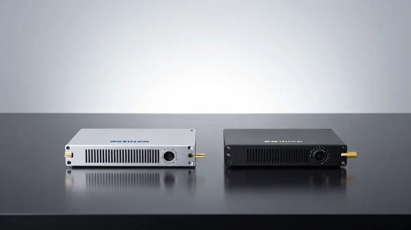
The choice between QSFP56 ER4 and other 200G variants is primarily dictated by the host system's hardware design and the intended roadmap for network scaling. While the QSFP56 ER4 is the industry standard for 4-lane 200G deployments in legacy-compatible environments, the emergence of QSFP-DD (Double Density) and OSFP (Octal Small Form-factor Pluggable) at the 200G tier provides unique advantages in port density and thermal management, albeit at the cost of increased complexity.
QSFP56 vs. QSFP-DD: Architectural Differences
The fundamental difference lies in the electrical interface. QSFP56 utilizes 4 lanes of 50G PAM4 to achieve 200G throughput, maintaining the same physical footprint as the traditional QSFP28. In contrast, QSFP-DD was designed for 400G by utilizing 8 lanes; when used for 200G, it may operate in a 'breakout' style or as a 200G-NRZ equivalent in some legacy configurations, though 200G QSFP-DD is less common for long-reach ER4 applications than the native QSFP56 solution.
| Feature | QSFP56 (ER4) | QSFP-DD (200G) | OSFP (200G) |
|---|---|---|---|
| Electrical Lanes | 4 x 50G PAM4 | 8 x 25G NRZ or 4 x 50G | 8 x 25G NRZ or 4 x 50G |
| Backwards Compatibility | QSFP+, QSFP28 | QSFP+, QSFP28, QSFP56 | Requires Adapter |
| Max Power Budget | ~5W - 7W | 7W - 12W | Up to 15W |
| Ideal Use Case | Dedicated 200G Networks | 400G Ready Infrastructure | High-Power Computing/AI |
Migration Strategy and Port Density
Network operators must evaluate their existing chassis. If a data center is built on a 200G-native switching fabric, the QSFP56 ER4 offers the most cost-effective and power-efficient method for long-range interconnects. However, for organizations deploying 400G-capable switches that plan to run ports at 200G temporarily, QSFP-DD may be the preferred variant due to its 'double density' design, allowing for seamless upgrades to 400G by simply swapping the transceiver without changing the physical line card.
Technical Considerations for Deployment
- Thermal Management
QSFP56 modules generally run cooler than QSFP-DD modules due to fewer active electrical lanes, making them easier to manage in high-density 1U top-of-rack switches. - Cost Efficiency
The 200G QSFP56 ecosystem is currently more mature for the ER4 40km reach, often resulting in lower per-unit costs compared to specialized QSFP-DD 200G long-reach optics. - Interoperability
QSFP56 ER4 is strictly defined by MSA standards for 4-lane operation, ensuring better plug-and-play reliability in multi-vendor 200G environments.
FAQ: Comparing 200G Form Factors
- Can I plug a QSFP56 ER4 into a QSFP-DD port?
Yes, QSFP-DD ports are designed to be backwards compatible with QSFP56 modules. The module will occupy the first four lanes of the 8-lane port. - Why choose OSFP for 200G?
OSFP is typically reserved for environments requiring extreme heat dissipation, such as AI clusters, though it is less common for ER4 long-haul applications. - Does 200G QSFP-DD offer better distance than QSFP56?
No, the reach is determined by the optical engine (e.g., ER4 for 40km). Both form factors can support the ER4 standard, but QSFP56 is the more prevalent choice for this specific distance.
The 200G QSFP56 ER4 represents a critical milestone in optical networking, providing the perfect balance of reach, power efficiency, and density for 40km applications. As you plan your next network upgrade, ensuring compatibility and technical alignment is paramount. Reach out to our technical consulting team today for a comprehensive compatibility assessment and a custom quote for your high-speed networking needs.