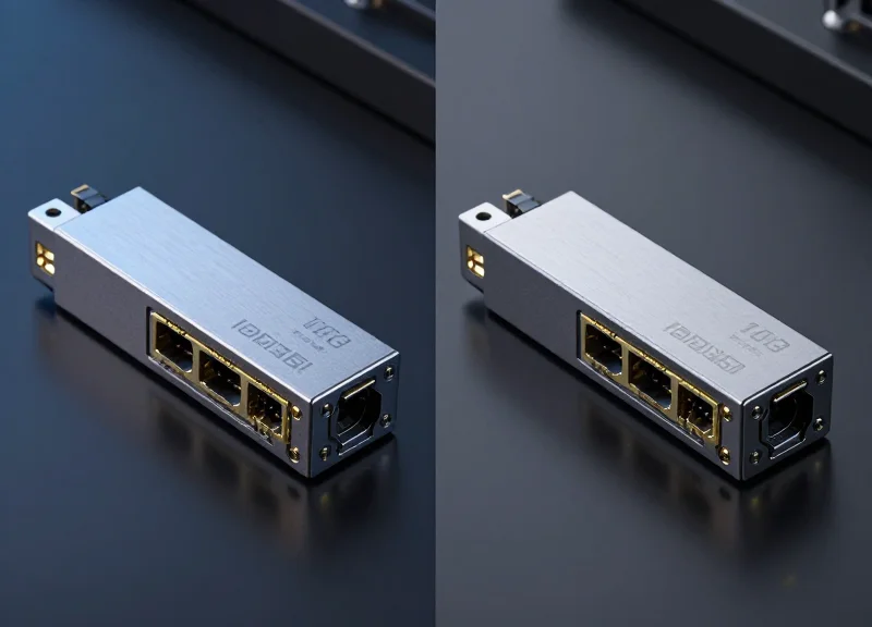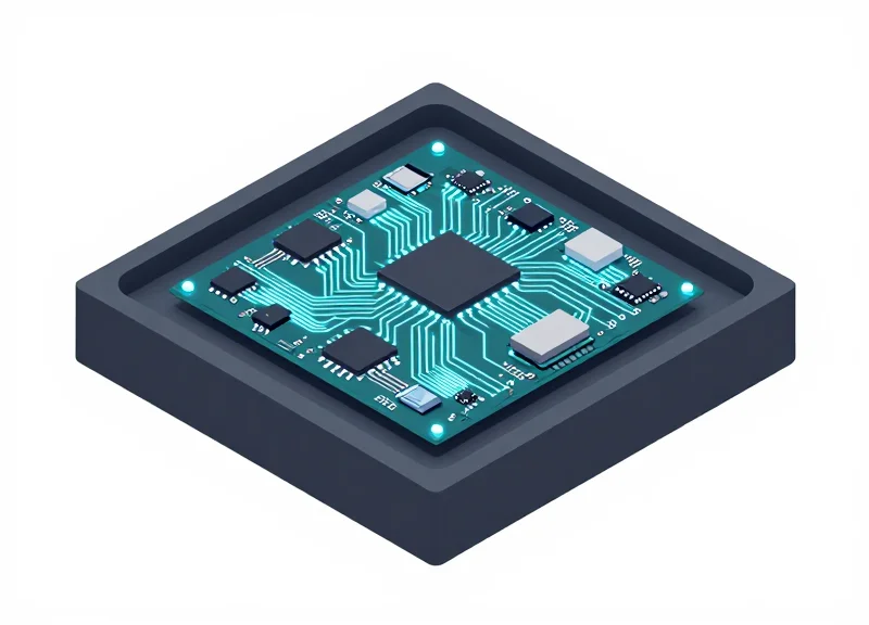
In the world of high-speed optical networks, hardware is only as capable as the code that controls it. Firmware serves as the critical bridge between silicon-level performance and network-level intelligence. As data centers transition to 400G and 800G speeds, understanding the nuances of firmware coding for switches becomes essential for network architects and engineers seeking to eliminate bottlenecks and ensure seamless interoperability.
Understanding the Fundamentals of Switch Firmware

Firmware coding for switches is the specialized engineering discipline of developing low-level software that instructs networking hardware on how to initialize, manage, and forward data packets at line rate. Unlike general-purpose software, switch firmware must interact directly with Application-Specific Integrated Circuits (ASICs) and Field Programmable Gate Arrays (FPGAs) to bridge the gap between physical electrical signals and complex networking protocols like BGP or OSPF. It acts as the permanent instruction set stored on the device's non-volatile memory, ensuring that the hardware logic is correctly orchestrated to handle high-density traffic without latency bottlenecks.
The Hierarchical Layers of Switch Firmware
To understand switch firmware, one must view it as a multi-layered stack rather than a single monolithic program. Each layer serves a distinct purpose in the lifecycle of a packet and the operational state of the device.
| Layer | Primary Responsibility | Typical Location |
|---|---|---|
| Bootloader | Hardware initialization and OS kernel loading | ROM / Flash Memory |
| Microcode / ASIC Firmware | Instruction sets for the data plane and packet forwarding | On-chip SRAM/TCAM |
| Network OS (NOS) | Control plane protocols and management interfaces | System Flash / SSD |
1. The Bootloader: The Root of Trust
The bootloader is the first code executed when a switch is powered on. Its primary role is to perform the Power-On Self-Test (POST), initialize the CPU, memory controllers, and internal buses, and subsequently locate and decompress the main operating system image. In modern enterprise switches, the bootloader also serves as a 'Root of Trust,' verifying digital signatures to ensure that the firmware has not been tampered with before execution.
2. Microcode and the Forwarding Engine
At the heart of a high-performance switch is the microcode. This is highly optimized code written to run on the switch’s ASIC. While the general CPU handles management tasks, the microcode dictates how the ASIC parses headers, performs lookups in the Ternary Content-Addressable Memory (TCAM), and executes switching logic. Coding at this level requires deep knowledge of hardware architecture and timing constraints, as it directly impacts the switch's throughput and 'wire-speed' capabilities.
3. The Network Operating System (NOS)
The NOS is the highest layer of firmware, providing the environment for the control plane. It manages the user interface (CLI/WebUI), SNMP agents, and the complex routing stacks that determine the best path for data. Whether it is a proprietary system like Cisco IOS or an open-source alternative like SONiC, the NOS abstracts the hardware complexity into a manageable software interface for network administrators.
Common Questions on Switch Firmware Fundamentals
- How does switch firmware differ from a standard PC BIOS?
While both perform hardware initialization, switch firmware remains active after boot to manage continuous high-speed data forwarding logic, whereas a PC BIOS typically hands off most control to the OS once the boot process is complete. - What is 'Bare Metal' switching in the context of firmware?
Bare metal switching refers to hardware sold without a pre-installed NOS. These switches use a specialized bootloader called ONIE (Open Network Install Environment) to allow users to install their choice of third-party firmware. - Why is microcode updated less frequently than the NOS?
Microcode is tied directly to the hardware gates of the ASIC. It is typically only updated to fix critical logic bugs or enable latent hardware features, whereas the NOS is updated frequently to add new protocols and security patches.
The Role of the Hardware Abstraction Layer (HAL)
The Hardware Abstraction Layer (HAL): Bridging Software and Silicon
In the context of switch firmware coding, the Hardware Abstraction Layer (HAL) is the critical intermediary that translates high-level Network Operating System (NOS) commands into low-level instructions understood by the Application-Specific Integrated Circuit (ASIC). By abstracting the complexities of the silicon—such as register mappings, memory buffer management, and pipeline stages—the HAL allows network engineers to develop software that is agnostic to the underlying hardware vendor. Whether the switch utilizes Broadcom, Marvell, or Intel/Nvidia silicon, the HAL ensures that the control plane can push routing tables and ACLs without needing to rewrite the entire codebase for each specific chip architecture.
Comparative Benefits of HAL-Driven Architectures
| Feature | Legacy Direct-Access Coding | Modern HAL-Based Abstraction |
|---|---|---|
| Portability | Extremely Low; locked to specific silicon | High; code runs on any supported ASIC |
| Development Cycle | Years; requires silicon-specific experts | Months; utilizes standardized APIs |
| Vendor Lock-in | High; software is proprietary to hardware | Low; facilitates 'White Box' networking |
| Error Handling | Manual register-level debugging | Standardized API return codes |
Standardizing the Forwarding Plane via SAI
One of the most significant advancements in firmware coding is the Switch Abstraction Interface (SAI). SAI is an open-source standard that defines the API to program the forwarding plane. Before SAI, each silicon vendor provided a proprietary SDK that required unique integration. Firmware developers now use SAI as a standardized layer within the HAL, allowing a single NOS (like SONiC) to manage diverse hardware platforms. This shift has transitioned switch firmware coding from a hardware-centric task to a more scalable software-defined engineering discipline.
- Does the HAL impact switching performance?
No. The HAL resides in the control plane and handles the configuration of the data plane. Once the ASIC is programmed via the HAL, packet forwarding happens at wire speed within the silicon itself. - What is the relationship between the HAL and the SDK?
The HAL sits above the vendor's Software Development Kit (SDK). It consumes the SDK's functions to perform the actual hardware manipulation while exposing a simplified, uniform API to the NOS. - Can a single firmware support multiple ASIC generations?
Yes, provided the HAL is updated to map existing software calls to the new register layouts or pipeline features of the newer silicon generation.
Packet Processing and Pipeline Management

Packet Processing and Pipeline Management
Packet processing in switch firmware is the critical logic layer that dictates how data moves through the silicon's ingress and egress pipelines. At its core, firmware must program the Network Processor or ASIC to handle high-velocity traffic by managing specialized memory structures and forwarding engines. While the hardware performs the heavy lifting of moving bits, the firmware is responsible for defining the 'rules of engagement'—populating forwarding databases, managing buffer thresholds, and ensuring that every packet is processed according to protocol standards without introducing jitter or latency.
Forwarding Engines and Table Lookups
Firmware manages the population and aging of lookup tables, which are essential for both Layer 2 (switching) and Layer 3 (routing). When a packet arrives, the firmware-driven logic initiates a lookup in the Forwarding Database (FDB) for MAC addresses or the Routing Information Base (RIB) for IP prefixes. This involves complex interactions with Hash Tables for exact matches and Longest Prefix Match (LPM) algorithms for routing, ensuring that the hardware can identify the destination port in a single clock cycle.
| Memory Type | Primary Use Case | Lookup Mechanism | Characteristics |
|---|---|---|---|
| SRAM / Hash Tables | L2 MAC Tables, VLAN IDs | Exact Match | High density, lower power, fast for 1:1 mappings. |
| TCAM | ACLs, QoS, Policy Routing | Ternary (0, 1, X) | Parallel search, supports 'Don't Care' bits, high power draw. |
| LPM Tree | L3 IPv4/IPv6 Routing | Prefix Match | Algorithmic search for the most specific route entry. |
TCAM Resource Optimization
Ternary Content Addressable Memory (TCAM) is a scarce and expensive resource within the switch silicon. Firmware coding plays a pivotal role in 'carving' or partitioning TCAM into slices for different features like Access Control Lists (ACLs), Quality of Service (QoS) markings, and telemetry. Efficient firmware must implement intelligent resource management to prevent 'table full' errors, which would otherwise force the switch to drop packets or divert them to the slower CPU (Control Plane) for processing, a condition known as 'punting'.
The Egress Pipeline and Buffer Logic
Once a forwarding decision is made, the firmware manages the egress pipeline where packets are queued and potentially modified. This includes header rewrites (such as TTL decrements or VLAN tagging) and applying traffic shaping policies. Firmware developers must carefully tune Weighted Round Robin (WRR) or Strict Priority (SP) scheduling algorithms to ensure that mission-critical voice or video traffic is prioritized over bulk data transfers during periods of network congestion.
- What is wire-speed forwarding?
It is the ability of the switch to process and forward packets at the maximum theoretical rate of the physical port without any frame loss, achieved by keeping the forwarding logic entirely within the hardware pipeline. - How does firmware handle 'punting'?
Punting occurs when the ASIC cannot handle a packet (e.g., an unknown protocol or an expired TTL). The firmware traps these packets and sends them to the local CPU for manual processing, which is significantly slower but necessary for protocol handling. - Why is TCAM management so complex?
Because TCAM allows for 'wildcard' matching (matching bits as 0, 1, or X), it is used for complex rules. Firmware must prioritize which rules reside in TCAM because it is limited by hardware size and high energy consumption.
Firmware Coding for Optical Transceiver Compatibility
Firmware Coding for Optical Transceiver Compatibility
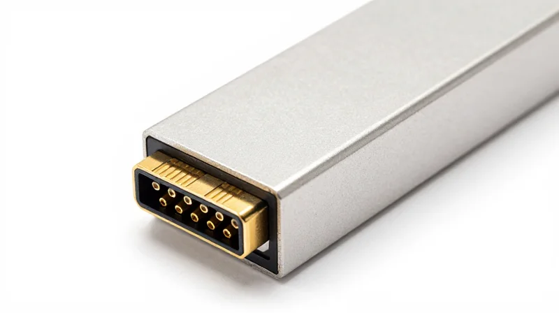
Firmware coding for optical transceiver compatibility is the process of implementing the Inter-Integrated Circuit (I2C) communication protocols and memory-mapping logic required for a switch to identify, authorize, and monitor pluggable modules. Because optical transceivers follow Multi-Source Agreement (MSA) standards, the firmware must accurately parse standardized memory addresses while often handling proprietary vendor-specific extensions to maintain signal integrity and prevent port lockout.
The I2C Bus and Memory Page Management
The switch firmware acts as the I2C master, initiating read/write operations to the transceiver's Electrically Erasable Programmable Read-Only Memory (EEPROM). In SFP+ modules, the firmware typically interacts with two primary 256-byte address spaces: 0xA0 (containing static identification data like vendor name and part number) and 0xA2 (containing real-time diagnostics). For higher-speed modules like QSFP28, the firmware must manage a more complex paging architecture to access the necessary control and status registers without overwhelming the low-speed bus.
| MSA Standard | Form Factor | Primary Memory Logic |
|---|---|---|
| SFF-8472 | SFP/SFP+ | Fixed two-wire address 0xA0 and 0xA2. |
| SFF-8636 | QSFP+ | Paging mechanism via address 0xA0; lower 128 bytes are static. |
| SFF-8436 | QSFP28 | Enhanced interrupt handling and high-speed signal tuning registers. |
Digital Diagnostic Monitoring (DDM) Integration
Digital Diagnostic Monitoring (DDM), also known as Digital Optical Monitoring (DOM), is a firmware-driven feature that enables the Network Operating System (NOS) to track the health of the optical link. The firmware continuously polls the transceiver's internal sensors to report critical metrics. If the firmware detects a value outside the factory-calibrated 'Warning' or 'Alarm' thresholds, it triggers a system interrupt to prevent hardware damage or data loss.
- TX/RX Optical Power
Measuring the strength of the transmitted and received laser signals in dBm. - Transceiver Temperature
Monitoring internal heat to prevent laser degradation or thermal shutdown. - Laser Bias Current
Tracking the current applied to the laser diode, which helps predict potential component failure.
Checksum Validation and Signal Optimization
During the module initialization phase, the firmware performs a checksum validation (usually CC_BASE or CC_EXT) to ensure the EEPROM data has not been corrupted. Beyond simple identification, the firmware is responsible for signal conditioning. This involves configuring the switch ASIC's SerDes (Serializer/Deserializer) settings—such as Pre-Emphasis, Differential Output Voltage, and Equalization—based on the specific requirements of the detected cable type (e.g., DAC vs. Active Optical Cable).
- How does firmware handle 'unsupported' transceivers?
Firmware checks the Vendor OUI (Organizationally Unique Identifier) and Part Number. If they don't match an internal whitelist, the firmware may disable the port or issue a warning, though many NOS allow an override command to 'unlock' third-party modules. - What is the impact of I2C clock stretching?
Clock stretching occurs when a slow transceiver holds the SCL line low to pause the firmware's read request. Robust firmware coding must include timeout logic to prevent a slow module from hanging the entire switch management bus.
Optimizing Throughput for 400G and 800G Architectures
At 400G and 800G speeds, firmware coding transitions from static configuration to active, real-time physical-layer management. As signal margins shrink due to the adoption of PAM4 (4-level Pulse Amplitude Modulation), the firmware must dynamically tune SerDes (Serializer/Deserializer) parameters and orchestrate complex Forward Error Correction (FEC) schemes to maintain a Bit Error Rate (BER) that allows for line-rate throughput without packet loss.
SerDes Tuning and PAM4 Signal Integrity
The jump to 100G-per-lane signaling in 800G architectures introduces extreme signal attenuation and crosstalk. Firmware developers implement 'Link Training' algorithms that allow the switch to negotiate optimal equalization settings with the connected transceiver or NIC. This involves the firmware fine-tuning the Continuous Time Linear Equalization (CTLE) and Decision Feedback Equalization (DFE) taps to open the 'eye diagram' of the signal. Unlike lower speeds where settings were often fixed, 800G firmware must perform iterative searches to compensate for variations in cable quality and temperature.
Adaptive Forward Error Correction (FEC)
Because PAM4 signals are inherently noisier than NRZ, hardware cannot achieve error-free transmission on its own. Firmware manages the FEC engine to correct bit errors in flight. Different cable types (DAC vs. AOC vs. Fiber) require different FEC strengths, and the firmware must often auto-negotiate these modes to balance error correction capability against the added latency.
| FEC Mode | Standard | Typical Latency | Application |
|---|---|---|---|
| RS-FEC (528, 514) | IEEE 802.3bj | ~100ns | 100G NRZ Links |
| KP4-FEC (544, 514) | IEEE 802.3bs | ~250ns | 400G/800G Standard |
| FEC-Bypass/None | Custom | <5ns | Ultra-low latency (HPC) |
Thermal Throttling and Power Efficiency
800G ASICs and high-density optical modules consume significant power, generating heat that can degrade signal performance or cause hardware failure. Firmware coding includes thermal management loops that monitor on-chip sensors. When temperature thresholds are exceeded, the firmware may implement 'graceful throttling'—reducing the clock speed of non-critical packet processing blocks or increasing cooling fan RPM—to maintain link stability without a total port shutdown.
FAQ: 400G/800G Firmware Challenges
- Why is link-up time longer on 800G switches?
The firmware must perform complex multi-lane link training and equalization tuning to account for PAM4 sensitivity, which takes significantly more time than simple NRZ signaling. - Can firmware fix a bad optical cable?
To an extent. Firmware can use more aggressive equalization or switch to a more robust FEC mode, but physical damage beyond the 'Pre-FEC BER' limit will still result in link failure. - What is 'Autoneg' in the context of 800G firmware?
It is the firmware-driven process where two connected devices negotiate their shared maximum speed and the specific FEC type to ensure they can communicate reliably.
The Rise of Programmable Silicon and P4
The evolution of switch firmware coding is currently defined by the transition from rigid, fixed-function Application-Specific Integrated Circuits (ASICs) to programmable data planes. Traditionally, packet processing logic was 'baked' into the hardware, meaning firmware developers were limited to the protocols and features supported by the silicon at the time of manufacture. With the rise of programmable silicon, such as Intel’s Tofino or Broadcom’s Trident series, firmware coding has shifted into a more agile domain where the data plane behavior can be defined after the hardware is deployed using specialized languages like P4 (Programming Protocol-independent Packet Processors).
The Shift from Fixed-Function to Programmable ASICs
In a fixed-function environment, the firmware serves primarily as a management layer for the pre-defined hardware tables (L2/L3). Programmable silicon, however, introduces a Protocol-Independent Switch Architecture (PISA). In this model, the firmware developer defines the parser, the match-action pipeline, and the de-parser. This allows for the implementation of proprietary protocols or the optimization of memory resources by removing unused legacy features to make room for larger routing tables or specialized filtering.
| Feature | Fixed-Function ASIC | Programmable Silicon (P4) |
|---|---|---|
| Protocol Support | Pre-defined (e.g., IPv4, IPv6, VXLAN) | Customizable & Upgradable via Software |
| Resource Allocation | Static table sizes | Dynamic (re-allocate TCAM/SRAM) |
| Telemetry | Standard SNMP/RMONT counters | In-band Network Telemetry (INT) |
| Development Cycle | Years (Hardware iteration) | Weeks/Months (Firmware/P4 update) |
Empowering Advanced Telemetry and Custom Protocols
One of the most significant advantages of programmable firmware coding is the ability to implement In-band Network Telemetry (INT). This allows the switch to insert metadata into packets—such as queue depths, hop latency, and timestamping—at wire speed. This level of granularity is impossible with fixed-function chips and provides network operators with real-time visibility into micro-bursts and congestion points that were previously invisible.
header custom_metadata_t {
    bit<32> switch_id;
    bit<32> ingress_tstamp;
    bit<32> egress_tstamp;
    bit<16> queue_depth;
}

control Ingress(inout headers h, inout metadata m) {
    apply {
        h.intel_telemetry.setValid();
        h.intel_telemetry.queue_depth = (bit<16>)standard_metadata.enq_qdepth;
    }
}
Common Questions on Programmable Silicon
- Does programmable silicon reduce switching performance?
No. Modern programmable ASICs use a PISA architecture that maintains 'wire-speed' performance, ensuring that even with custom P4 logic, the throughput remains consistent with fixed-function counterparts. - What is the primary role of P4 in firmware coding?
P4 is used to describe how the data plane processes packets. It tells the hardware which headers to look for, what fields to extract, and what actions to take (e.g., modify, drop, or forward) based on table lookups. - Can I run P4 on any switch?
No, the hardware must have a programmable pipeline. While most white-box switches now offer programmable options, legacy proprietary switches often remain fixed-function.
Security at the Firmware Level
Security at the Firmware Level
Security at the firmware level is the primary defense against persistent threats that target the foundation of a network switch's operational logic. By embedding security protocols directly into the boot sequence and the firmware update process, developers ensure that the device only executes authenticated, untampered code. This 'zero trust' approach at the silicon level prevents malicious actors from installing persistent backdoors or modifying traffic-handling instructions, which could otherwise lead to catastrophic network-wide breaches.
The Chain of Trust: Secure Boot and Hardware RoT
The security architecture of a modern switch begins with a Hardware Root of Trust (RoT), typically a dedicated security chip or a secure enclave within the ASIC itself. This component contains an immutable public key used to verify the initial bootloader. If the signature is valid, the bootloader then verifies the next stage of the OS or firmware. This sequential verification, known as Secure Boot, ensures that every piece of software running on the switch is authorized by the manufacturer.
| Security Feature | Legacy Boot Process | Secure Boot Process |
|---|---|---|
| Initial Code Source | Internal Flash (Unverified) | Immutable ROM (Root of Trust) |
| Integrity Check | None or Basic Checksum | Cryptographic Signature Verification |
| Unauthorized Firmware | Will execute and run | System halts to prevent breach |
| Persistence Protection | Vulnerable to bootkits | Resistant to low-level malware |
Firmware Image Signing and Integrity Checks
Firmware signing utilizes asymmetric cryptography to guarantee the authenticity of software updates. When a developer compiles a new firmware version, they sign the binary using a private key. The switch hardware uses a corresponding public key, stored in a write-protected area, to decrypt the signature and compare the hash of the downloaded image. If the hashes do not match, the update is rejected, preventing attackers from injecting malicious payloads via 'Man-in-the-Middle' attacks during the update process.
VERIFY_SIGNATURE(firmware_blob, manufacturer_public_key)
IF HASH(firmware_blob) == DECRYPT(signature, manufacturer_public_key):
    PROCEED_WITH_BOOT()
ELSE:
TRIGGER_SECURITY_HALT()- Why is Hardware Root of Trust (RoT) essential?
Software-based security can be bypassed if the OS is compromised; hardware RoT provides a physical, immutable starting point that cannot be altered by software exploits. - How does firmware coding prevent lateral movement?
By implementing strict control over the management plane and encrypting configuration data at rest, firmware prevents an attacker who has compromised one switch from easily accessing administrative credentials for the rest of the network. - What happens if a firmware signature check fails?
The switch typically enters a recovery mode or remains in a 'halt' state, requiring a physical factory reset or an authenticated recovery image to ensure the system does not run potentially malicious code.
Open Source vs. Proprietary Firmware Ecosystems
Open Source vs. Proprietary Firmware Ecosystems
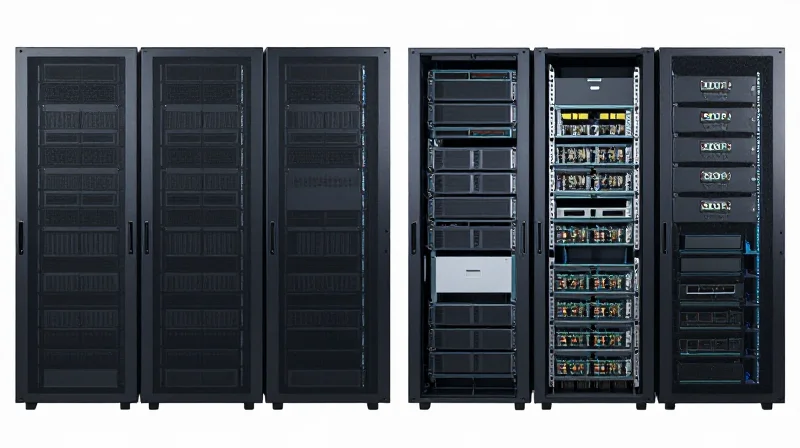
The choice between proprietary and open-source firmware defines the operational flexibility and hardware lifecycle of a modern data center. Proprietary firmware represents a vertically integrated approach where the hardware and software are co-optimized by a single vendor, whereas open-source ecosystems focus on disaggregation—decoupling the network operating system (NOS) from the underlying silicon to prevent vendor lock-in and foster rapid innovation.
The Proprietary Standard: Integration and Optimization
Traditional networking giants like Cisco (Cisco IOS-XE), Juniper (Junos OS), and Arista (EOS) develop proprietary firmware stacks designed to extract maximum performance from their specific hardware architectures. These ecosystems are characterized by deep integration between the firmware and the ASIC, providing highly stable environments, comprehensive global support, and unified management planes. However, this model often leads to higher licensing costs and restricts the user to the vendor’s hardware upgrade cycle and feature roadmap.
The Open Source Movement: Disaggregation and Customization
Driven by the Open Compute Project (OCP), the shift toward open-source firmware allows organizations to run a single software stack across diverse hardware from multiple vendors. This is achieved through a 'White Box' or 'Brite Box' model. By leveraging open-source components, engineers can customize the firmware at a granular level, implementing only the protocols they need and integrating directly with DevOps orchestration tools like Ansible or Terraform.
| Feature | Proprietary Firmware | Open Source Firmware (SONiC/ONIE) |
|---|---|---|
| Hardware Choice | Vendor-locked | Multi-vendor (White Box) |
| Control | Restricted to vendor APIs | Full access to source code |
| Support | Direct vendor TAC support | Community or third-party (e.g., Aviz) |
| Innovation Speed | Dependent on vendor releases | Rapid community-driven cycles |
| Complexity | Lower (Turn-key) | Higher (Requires in-house expertise) |
Pillars of Open Source Networking
- ONIE (Open Network Install Environment)
An open-source bootloader that allows a switch to automatically discover and install a Network Operating System, acting as the foundation for hardware disaggregation. - SONiC (Software for Open Networking in the Cloud)
A Linux-based NOS developed by Microsoft that utilizes containerization to decouple network functional modules, allowing for modular updates and high reliability. - SAI (Switch Abstraction Interface)
The critical API layer that allows the NOS (like SONiC) to communicate with different vendor ASICs (Broadcom, Mellanox, Barefoot) without requiring custom code for each.
Ecosystem FAQ
- Is open-source firmware as secure as proprietary options?
While proprietary vendors offer rigorous internal testing, open-source firmware benefits from public audits and 'many eyes' on the code. Both require Secure Boot and hardware Root of Trust (RoT) for enterprise-grade security. - Why would a company choose proprietary over open source?
Enterprises without a dedicated DevOps or network engineering team often prefer proprietary firmware for the 'single-pane-of-glass' management and the guarantee of professional technical support and warranties. - Can I run SONiC on any switch hardware?
No, the hardware must be OCP-compliant and have a supported Switch Abstraction Interface (SAI) driver for the specific ASIC used in the device.
Debugging and Performance Monitoring Tools
The Critical Role of Specialized Debugging Tools in Firmware
Debugging switch firmware is a unique challenge because it requires simultaneous visibility into the control plane software, the ASIC's internal state, and the physical signal integrity of high-speed SerDes. Unlike standard application debugging, where a debugger might pause execution, switch firmware often deals with real-time data streams where stopping a process could drop millions of packets or cause a synchronization failure across the network fabric. Effective firmware coding for switches relies on a multi-layered approach that integrates low-level hardware probes with high-level software telemetry to ensure deterministic performance.
Hardware Probing and SDK-Level Validation
At the most fundamental level, developers use JTAG (Joint Test Action Group) interfaces to interact with the CPU and ASIC registers before the operating system is even loaded. Logic analyzers are employed to monitor MII/GMII interfaces and control signals, ensuring the firmware correctly configures the PHY (Physical Layer) and handles reset sequences. Once the operating environment is stable, developers move to SDK-specific tools provided by silicon vendors. These SDKs offer shell interfaces that allow for real-time register reads, buffer monitoring, and L2/L3 table inspection without interrupting the data plane, providing a window into how the silicon is executing the firmware's instructions.
| Tool Category | Specific Tools | Primary Function |
|---|---|---|
| Hardware Probes | JTAG, Logic Analyzers | Signal integrity and early-boot register validation |
| SDK Interfaces | Vendor Shells (BCM, SDKLT) | Runtime ASIC state inspection and table management |
| Software Simulation | P4-BMv2, ASIC Emulators | Pre-silicon logic validation and protocol testing |
| Network Telemetry | gNMI, In-band Telemetry (INT) | Real-time performance monitoring and traffic analysis |
Real-Time Telemetry and Performance Export
Modern firmware must do more than just route packets; it must provide granular data about its own performance to maintain network health. Advanced firmware coding incorporates telemetry export mechanisms such as gNMI (gRPC Network Management Interface) or Streaming Telemetry. These protocols allow the switch to push data—such as queue depths, drop counters, and latency metrics—to external collectors at sub-second intervals. In programmable pipelines, In-band Network Telemetry (INT) is often implemented within the firmware to insert metadata into packet headers, providing a hop-by-hop view of the packet's journey through the fabric without requiring external probes.
- Why is JTAG used in switch firmware development?
JTAG provides a direct hardware link to the processor and ASIC, allowing developers to debug the bootloader, flash firmware images, and inspect memory addresses when the high-level OS is unresponsive. - What is the difference between simulation and emulation in this context?
Simulation (like BMv2) uses software to mimic the logic of a switch for protocol testing, while emulation often uses specialized hardware (like FPGAs) to run the actual firmware code at speeds closer to the final ASIC performance. - How does gNMI improve firmware monitoring?
gNMI uses a push-based model over gRPC, which is significantly more efficient than traditional pull-based SNMP polling, allowing for higher-resolution performance data.
Firmware is the unsung hero of the modern data center, enabling the extreme speeds and reliability required by today's cloud applications. As networking moves toward greater programmability, mastering firmware logic is key to building future-proof infrastructure. Explore our technical resources or contact our engineering team today to optimize your high-speed switch deployments.