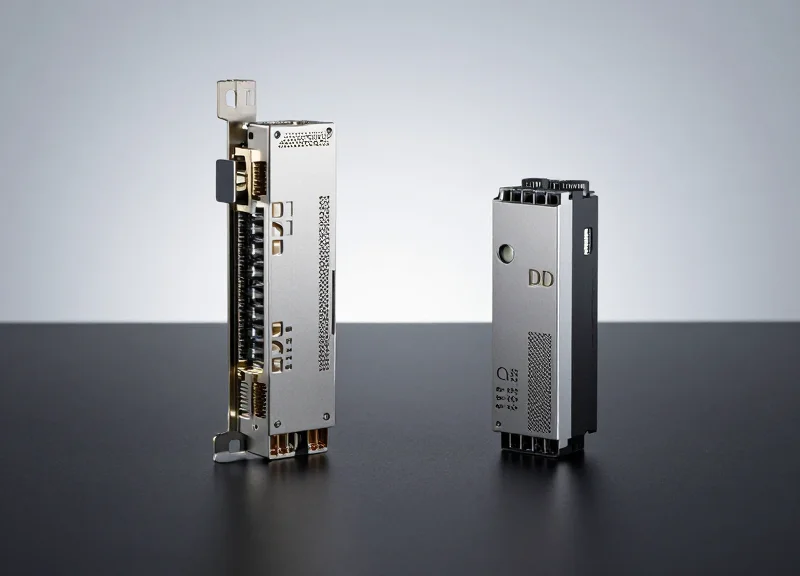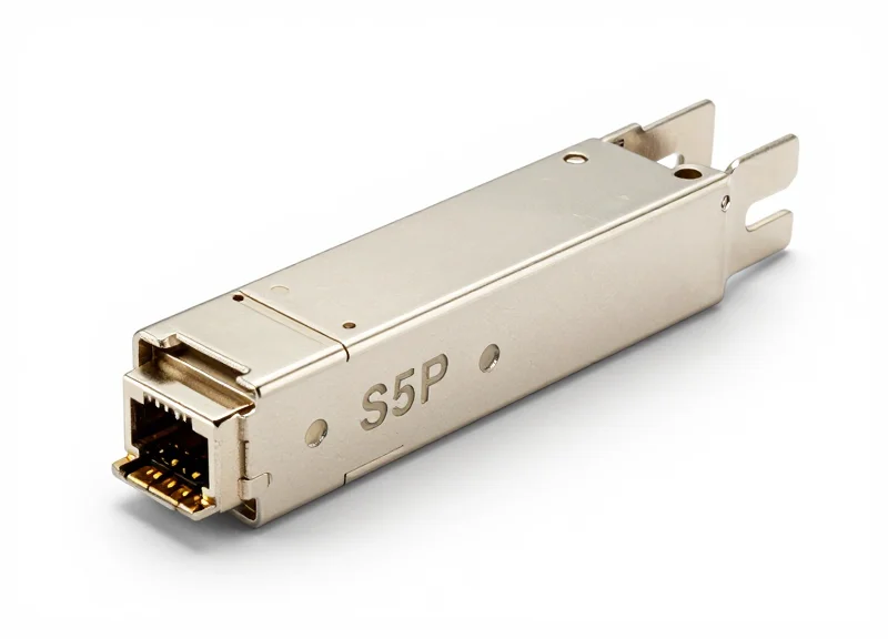
In the rapidly evolving landscape of high-speed data communications, the ability of hardware from different vendors to work together flawlessly is not just a luxury—it is a technical necessity. This article explores the critical role of Interoperability Testing (IOT) in modern optical networks, addressing how engineers overcome compatibility hurdles to build scalable, high-performance infrastructures.
Defining Interoperability Testing (IOT) in Optical Networking
Defining Interoperability Testing (IOT) in Optical Networking
Interoperability Testing (IOT) is a specialized verification process designed to ensure that networking components from multiple manufacturers—such as optical transceivers, switches, and routers—can operate together seamlessly while meeting established performance benchmarks. In the context of optical communications, IOT focuses on the ability of these disparate systems to establish stable physical links and exchange data packets without errors, even when they utilize different internal architectures or proprietary implementations of industry standards.
The Shift from Homogeneous to Multi-Vendor Ecosystems
Historically, optical networks were often built using a single-vendor 'vertical' stack, where the same manufacturer provided the switch, the software, and the optics. However, the rise of open networking and disaggregated architectures has made IOT essential. Today, network operators must verify that a 400G QSFP-DD transceiver from one vendor can communicate effectively across a fiber link with a switch from another vendor, ensuring that the Common Management Interface Specification (CMIS) and other protocols are interpreted identically across all devices.
| Feature | Interoperability | Compatibility |
|---|---|---|
| Primary Goal | Seamless communication between different vendor products. | Ensuring a product works within a specific environment or system. |
| Standards Focus | Adherence to IEEE, OIF, and MSA multi-vendor standards. | Adherence to specific host or proprietary requirements. |
| Typical Testing Scenario | Connecting Vendor A's transceiver to Vendor B's switch. | Verifying a transceiver fits and functions in a specific switch model. |
Foundational Questions in IOT
- What is the primary objective of IOT for transceivers?
The goal is to ensure that signal integrity, Bit Error Rate (BER), and power levels are maintained across the link, regardless of the transceiver manufacturer. - Does IOT involve software validation?
Yes, IOT includes validating the software-level interactions, such as the management interface and Diagnostic Optical Monitoring (DOM) accuracy, between the host switch and the pluggable module. - How does IOT reduce Total Cost of Ownership (TCO)?
By validating multi-vendor support, operators can avoid vendor lock-in, enabling them to source the best-performing or most cost-effective components from a wider market.
The Foundation: Multi-Source Agreements (MSAs)
Defining the Blueprint for Compatibility
Multi-Source Agreements (MSAs) are industry-wide collaborations between hardware manufacturers to establish standardized designs for optical transceivers, cables, and other network components. In the context of Interoperability Testing (IOT), MSAs serve as the 'contract' that ensures a module from Vendor A will physically fit into and electrically communicate with a switch from Vendor B. Without these agreements, the market would be fragmented by proprietary form factors, making standardized testing impossible.
Hardware Baselines: QSFP-DD vs. OSFP
Two of the most critical MSAs in modern high-speed networking are QSFP-DD and OSFP. These agreements define everything from the mechanical dimensions of the pluggable module to the pinout of the electrical interface. During IOT, engineers verify that hardware adheres to these specs to avoid mechanical interference or electrical shorts.
| Specification Category | QSFP-DD (Quad Small Form-factor Pluggable Double Density) | OSFP (Octal Small Form-factor Pluggable) |
|---|---|---|
| Interface Lanes | 8 lanes of electrical signaling | 8 lanes of electrical signaling |
| Backward Compatibility | Directly compatible with QSFP28 and QSFP+ ports | Requires a mechanical adapter for QSFP compatibility |
| Thermal Management | Designed for modules up to 15W; relies on host-side cooling | Designed for 15W-30W; includes integrated heat sinks |
| Primary Use Case | High-density data center switching and routing | Next-generation 800G and AI/ML clusters with high power requirements |
Logical Interoperability via CMIS
The foundation of MSAs extends into the software layer through the Common Management Interface Specification (CMIS). This part of the MSA defines the memory map and register structures used by the host system to monitor and control the transceiver. IOT testing rigorously checks if a module correctly reports its diagnostic data (DDM/DOM) and responds to control signals as defined by the CMIS standard, ensuring seamless software integration across disparate hardware.
- Are MSAs the same as IEEE standards?
No. IEEE standards (like 802.3ck) define how data is transmitted over the fiber, while MSAs define the physical package, power levels, and management interfaces of the transceiver hardware itself. - What happens if a device is not MSA-compliant?
Non-compliant devices may fail to initialize, suffer from excessive heat, or even cause physical damage to the host port, leading to immediate failure in any interoperability testing scenario. - Why do we need multiple MSAs like OSFP and QSFP-DD?
Different MSAs address different engineering trade-offs, such as the OSFP's superior thermal performance for high-power AI applications versus the QSFP-DD's legacy compatibility for enterprise data centers.
Critical Technical Parameters Evaluated During IOT

Critical Technical Parameters Evaluated During IOT
Interoperability Testing (IOT) validates the technical performance of a network link by measuring how well disparate hardware components adhere to standardized physical layer (PHY) specifications. It moves beyond simple link-up status to analyze the quality of the optical signal, ensuring that data integrity remains intact despite variations in vendor-specific chipsets or laser drivers.
Optical Power and Receiver Sensitivity
The primary physical metric in IOT is the Optical Power Level. Testing ensures that the Transmit (Tx) power of Vendor A falls within the acceptable Dynamic Range of Vendor B’s Receiver (Rx). If Tx power is too high, it saturates the photodiode, causing signal distortion; if too low, the signal-to-noise ratio drops below the threshold for data recovery. IOT measures 'Optical Budget' to account for losses in connectors, patches, and fiber spans across multi-vendor environments.
Bit Error Rate (BER) and FEC Performance
Bit Error Rate (BER) is the ultimate arbiter of link quality. In high-speed 400G and 800G links, IOT focuses on Pre-Forward Error Correction (Pre-FEC) BER. Because modern PAM4 signaling is inherently noisier than traditional NRZ, engineers must ensure the Pre-FEC BER is low enough—typically below 2E-4—to allow FEC algorithms to achieve a Post-FEC BER of < 1E-15, which is effectively error-free. Testing checks if Vendor A's FEC implementation correctly interprets the parity bits sent by Vendor B.
Eye Diagram Analysis and Signal Integrity
The Eye Diagram is a fundamental tool for visualizing signal health. In IOT, 'Eye Mask' testing ensures that the waveform does not encroach upon defined exclusion zones. For PAM4 signals, which have three distinct eyes, IOT evaluates Transmitter Linearity and Eye Closure Power Penalty (TDECQ). These metrics determine if the signal's vertical and horizontal openings are sufficient to distinguish between different voltage levels under real-world jitter conditions.
| Parameter | Target Metric | Significance in IOT |
|---|---|---|
| Pre-FEC BER | < 2.4e-4 (PAM4) | Ensures signal is clean enough for error correction. |
| TDECQ | < 3.4 dB | Quantifies transmitter quality and dispersion penalty. |
| ER (Extinction Ratio) | > 3.5 dB | Measures the clarity between 'on' and 'off' states. |
| OSNR | > 15-20 dB | Defines signal clarity against optical noise floor. |
Signal-to-Noise Ratio (SNR) and OSNR
While electrical SNR is critical at the transceiver's DSP, Optical Signal-to-Noise Ratio (OSNR) is the key metric for long-haul interoperability. OSNR measures the ratio of the service signal power to the noise power introduced by optical amplifiers (EDFAs). IOT verifies that different transceivers can maintain a stable link even when the OSNR approaches the theoretical limit, testing the robustness of the receiver's adaptive equalization filters.
Technical Parameter FAQ
- Why is TDECQ important in 400G IOT?
TDECQ replaces traditional eye-mask testing for PAM4 signals, measuring the additional power needed to achieve a target BER compared to an ideal signal. - What happens if Tx power exceeds Rx sensitivity?
This results in receiver saturation, causing a massive increase in BER and potentially permanent damage to the photodetector. - Does IOT test Jitter specifically?
Yes, IOT evaluates both Random Jitter (RJ) and Deterministic Jitter (DJ) to ensure timing synchronization across the clock recovery circuits of different vendors.
The Challenges of 400G and 800G Multi-Vendor Environments
The Challenges of 400G and 800G Multi-Vendor Environments
As data rates climb to 400G and 800G, interoperability testing (IOT) shifts from a simple connectivity check to a high-stakes validation of complex signal processing and physics. The transition from 100G NRZ (Non-Return to Zero) to PAM4 (Four-Level Pulse Amplitude Modulation) dramatically reduces signal margins, meaning that slight variations in transceiver design or switch port tuning between different vendors can lead to total link failure or unacceptable packet loss.
PAM4 Modulation and Signal Integrity
Unlike the binary logic of NRZ, PAM4 uses four distinct signal levels to pack two bits of data into every symbol. This effectively doubles the data rate without requiring double the bandwidth, but it comes at a cost: the Signal-to-Noise Ratio (SNR) is reduced by approximately 9.6 dB. In a multi-vendor environment, ensuring that a 'Level 1' from Vendor A is interpreted correctly as a 'Level 1' by Vendor B requires precision timing and equalization (EQ) settings that must be rigorously tested during IOT.
| Parameter | 100G (NRZ) | 400G/800G (PAM4) |
|---|---|---|
| Signal Levels | 2 (High/Low) | 4 (0, 1, 2, 3) |
| SNR Tolerance | High | Very Low (~9.6dB penalty) |
| Error Correction | Optional/Minimal | Mandatory (KP4 FEC) |
| Primary IOT Focus | Optical Power/Link Up | Pre-FEC BER/Equalization |
The FEC Synchronization Paradox
At 400G and 800G, native Bit Error Rates (BER) are too high for standard networking protocols to handle without assistance. Forward Error Correction (FEC)—specifically KP4 FEC—is utilized to identify and correct bit errors on the fly. However, different silicon vendors implement FEC logic and alignment markers with subtle variations. Interoperability testing must ensure that the FEC engine on the host switch can successfully synchronize with the FEC logic inside the pluggable module, maintaining a stable link even when the 'Pre-FEC BER' is high.
- Why is 800G harder to test than 400G?
800G utilizes 112G electrical lanes, which are significantly more sensitive to trace length, crosstalk, and impedance mismatches than the 56G lanes used in 400G. - What is the role of the DSP in 400G IOT?
The Digital Signal Processor (DSP) compensates for signal degradation; IOT must verify that the DSP's adaptive equalization algorithms are compatible with the host system's firmware. - Can different FEC types interoperate?
Generally, no. Both ends of the link must agree on the FEC type (e.g., RS-FEC or KP4) and the specific alignment protocols, which is a major focus of multi-vendor testing.
Standardized Testing Methodologies and Lab Frameworks
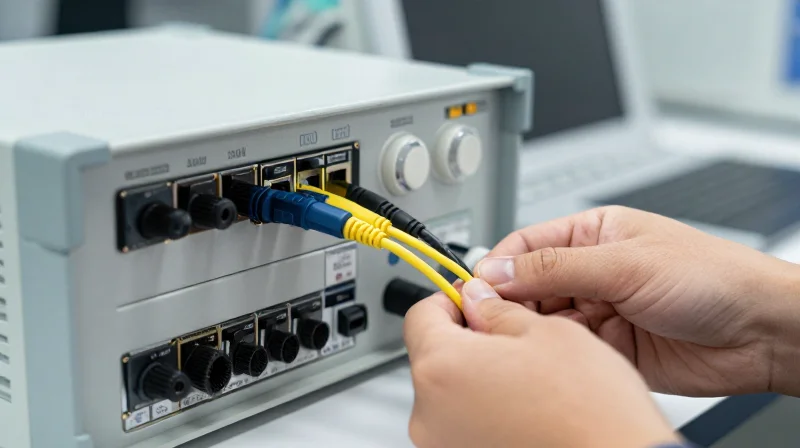
Standardized testing methodologies provide the structured environment necessary to isolate variables and verify that hardware from disparate manufacturers adheres to international specifications. In modern high-speed networking, IOT lab frameworks rely on a combination of active traffic generation, passive monitoring, and physical layer stress testing to ensure that a link remains stable under both nominal and worst-case operating conditions. By adhering to standardized topologies, engineers can replicate real-world data center conditions while maintaining the precision needed for granular troubleshooting.
The Architecture of Professional IOT Lab Frameworks
A professional IOT lab framework is designed around the concept of 'Link Verification.' This involves placing a Device Under Test (DUT) in a controlled loop with a Link Partner (LP) from a different vendor. The methodology focuses on three distinct phases: Physical Layer Validation, Protocol Handshaking, and Long-term Stress Testing. During these phases, the framework must account for environmental variables, including power supply fluctuations and thermal variances, to ensure the interoperability is not just a 'lucky connection' but a robust, repeatable state.
Key Instrumentation and Their Roles
| Instrument | OSI Layer Focus | Primary Capability |
|---|---|---|
| Bit Error Rate Tester (BERT) | Layer 1 (Physical) | Generates PRBS patterns to measure signal integrity and pre-FEC/post-FEC BER. |
| Protocol Analyzer | Layer 2-4 (Data Link/Network) | Captures and decodes handshaking sequences to identify state machine failures. |
| Digital Storage Oscilloscope | Physical Layer | Visualizes PAM4/NRZ eye diagrams to analyze jitter, noise, and signal-to-noise ratio (SNR). |
| Optical Power Meter | Physical Layer | Ensures that optical signals stay within the sensitivity range of the receiving transceiver. |
Advanced Testing Methodologies
Beyond simple connectivity, modern IOT frameworks utilize specific methodologies to evaluate the safety margins of a multi-vendor system. These methodologies ensure that even as hardware ages or environmental conditions change, the devices remain compatible.
- Negative Testing
This involves intentionally introducing malformed packets or invalid protocol states to verify that the multi-vendor environment can recover gracefully without a system crash. - Margin Analysis
Engineers gradually degrade the signal quality using variable optical attenuators or artificial noise injection to determine the exact point where the link fails. - Corner Case Validation
Testing the extreme ends of the specification, such as maximum supported cable lengths or minimum power levels, to ensure interoperability across the entire spec range.
Standardized Lab Framework FAQ
- What is the role of a BERT in interoperability testing?
A BERT (Bit Error Rate Tester) generates standardized bit patterns to stress the physical medium, allowing engineers to calculate the exact ratio of errored bits to total bits transmitted across a multi-vendor link. - Why are protocol analyzers necessary if the link is 'Up'?
Even if a link is physically active, protocol analyzers can detect 'silent' errors, such as frequent retransmissions or subtle timing issues in the Autonegotiation phase that reduce throughput. - How do 'Golden Systems' benefit IOT labs?
A Golden System is a reference device known to be 100% compliant with standards; it serves as the benchmark against which all new multi-vendor hardware is measured during the initial testing phase.
Strategic Benefits: Reducing TCO and Preventing Vendor Lock-in

Strategic Benefits: Reducing TCO and Preventing Vendor Lock-in
Rigorous IOT empowers enterprises to architect modular, best-of-breed infrastructures where components from disparate manufacturers coexist seamlessly, effectively decoupling infrastructure growth from proprietary hardware constraints and premium pricing models.
Optimizing Total Cost of Ownership (TCO)
By validating that third-party hardware, such as optical transceivers or network interface cards, functions correctly within an existing ecosystem, organizations can bypass the significant brand premiums typical of single-source providers. IOT ensures these lower-cost alternatives meet specific performance and reliability benchmarks. This validation process translates to immediate CapEx savings and long-term OpEx efficiency, as standardized interfaces simplify maintenance and reduce the complexity of troubleshooting across heterogeneous environments.
| Metric | Single-Vendor Ecosystem | Multi-Vendor (Validated by IOT) |
|---|---|---|
| Procurement Costs | Premium pricing (proprietary markup) | Competitive market pricing |
| Supply Chain Risk | High (Single point of failure) | Low (Diversified supplier base) |
| Innovation Cycle | Tied to vendor roadmap | Adoption of best-of-breed tech |
| Asset Longevity | Forced end-of-life upgrades | Incremental component replacement |
Mitigating Lock-in and Supply Chain Fragility
Vendor lock-in represents a significant business risk, where the technical cost of switching suppliers becomes a barrier to operational flexibility. IOT serves as an insurance policy against this risk. By verifying compliance with global standards—such as those defined by the IEEE or the OCP—enterprises ensure they can pivot to alternative suppliers if a primary vendor experiences supply chain disruptions, lead-time delays, or unfavorable shifts in licensing models. This flexibility is critical for maintaining high-speed network availability in volatile markets.
Strategic FAQ: IOT and Financial Efficiency
- How does IOT directly impact procurement strategy?
It allows procurement teams to leverage competition between vendors by providing technical proof that lower-cost hardware can meet the same operational requirements as premium-branded alternatives. - Does the cost of IOT outweigh the savings?
No; while IOT requires an initial investment in lab time or third-party validation, it prevents the exponential costs associated with network-wide failures, vendor-specific outages, or the inability to scale due to hardware shortages. - How does IOT improve supply chain resilience?
By qualifying multiple vendors for the same role in the network architecture, IOT ensures that a business can seamlessly substitute components if one supplier fails to deliver.
Software Interoperability: Firmware and Management Interfaces
Software Interoperability: Firmware and Management Interfaces
Software interoperability in the context of IOT represents the 'invisible' layer of connectivity where management interfaces allow a host system to communicate with pluggable modules or peripheral hardware. Beyond physical link stability, the firmware must align with strict industry standards to allow for real-time monitoring, diagnostic reporting, and control signaling. Without precise alignment of memory maps and communication protocols, a module might achieve a physical link but remain 'invisible' or unmanageable by the host operating system.
Standardized Memory Maps and EEPROM Structures
The foundation of firmware interoperability lies in the EEPROM (Electrically Erasable Programmable Read-Only Memory) located within the pluggable components. Standards such as SFF-8472 and SFF-8636 define the specific byte addresses for vendor information, serial numbers, and Digital Diagnostic Monitoring (DDM) data. IOT ensures that when a host reads these registers via the I2C bus, the data is interpreted correctly. Mismatches often occur when vendors use 'reserved' bits for proprietary features, leading to system crashes or incorrect temperature and power readings.
| Interface Protocol | Primary Use Case | Data Rate | Addressing Capability |
|---|---|---|---|
| I2C (Inter-Integrated Circuit) | Standard for SFP/QSFP management | Up to 400 kbps (Standard) | 7-bit or 10-bit addressing |
| MDIO (Management Data I/O) | High-speed PHY management (IEEE 802.3) | Up to 2.5 MHz | 32 registers per PHY |
| I3C | Next-gen sensor and module management | Up to 12.5 MHz | Backward compatible with I2C |
The Role of Sideband Signaling and I2C Communication
Management interoperability also extends to sideband signals—low-speed lines like ModSelL (Module Select), ResetL, and LPMode (Low Power Mode). These signals operate in tandem with the I2C software interface to manage the module lifecycle. IOT validates the timing requirements of these signals; for instance, ensuring that the host does not attempt to read the EEPROM before the module's internal micro-controller has fully initialized after a power-on reset.
- Why do DDM readings sometimes fail in multi-vendor setups?
Failures usually occur due to non-compliant memory maps where the vendor has placed diagnostic data in non-standard registers, or due to I2C bus contention caused by clock stretching issues. - How does firmware versioning impact IOT?
Firmware updates can change the behavior of internal state machines. Continuous IOT is required to ensure that new firmware releases do not break backward compatibility with older host OS drivers. - What is the impact of an incorrect Checksum in the EEPROM?
Most host systems perform a checksum validation of the EEPROM content upon insertion. If the checksum fails due to a vendor encoding error, the host will typically disable the port entirely for security and stability.
Real-World Case Studies in Hyperscale Data Centers

Operationalizing IOT in Hyperscale Environments
Hyperscale data centers, operated by cloud titans like AWS, Google, and Microsoft, utilize Interoperability Testing (IOT) as a cornerstone of their infrastructure strategy to prevent vendor lock-in and ensure seamless scaling. Unlike smaller enterprises that may rely on a single equipment provider, hyperscalers mix and match optical transceivers, network interface cards (NICs), and switches from dozens of manufacturers. IOT in this context is not just a compatibility check; it is a high-stakes validation process that ensures third-party hardware adheres to strict performance envelopes, low-latency requirements, and standardized communication protocols like I2C for management interfaces.
Case Study: 400G Multi-Vendor Ethernet Deployment
A prominent global cloud provider recently executed a massive migration to 400G Ethernet across its North American regions. To maintain supply chain resilience, they sourced QSFP-DD transceivers from five different vendors. The IOT phase involved a tiered validation approach: first, verifying the physical layer (Layer 1) for signal integrity using Bit Error Rate Testers (BERT); second, validating the Forward Error Correction (FEC) interoperability across different ASIC architectures; and finally, stress-testing the modules under high thermal loads to ensure heat dissipation did not impact neighboring ports. This rigorous IOT allowed the provider to swap vendors dynamically based on lead times without risking link stability or network-wide packet loss.
| Metric | Hyperscale IOT Requirements | Enterprise IOT Requirements |
|---|---|---|
| Scale of Nodes | 100,000+ per cluster | 100 - 5,000 per site |
| Vendor Strategy | Mandatory multi-vendor sourcing | Primarily single or dual-vendor |
| Validation Depth | Component-level (EEPROM, I2C, Firmware) | System-level (Plug-and-Play) |
| Success Threshold | Post-FEC BER < 1E-15 | Standard link-up status |
Automated Test Beds and Continuous IOT
To keep pace with rapid firmware updates and hardware revisions, hyperscale operators implement automated IOT test beds. These environments use DevOps principles to continuously run scripts that cycle through thousands of power-up sequences and data-heavy traffic bursts. By automating the validation of EEPROM memory maps and firmware parity, operators can detect potential regressions before new hardware is deployed to the production floor, effectively reducing the Mean Time to Repair (MTTR) and shielding the end-user from underlying hardware complexities.
- How do hyperscalers manage different firmware versions during IOT?
Hyperscalers use centralized management software to enforce a 'Gold Standard' firmware version for each hardware class, validated through IOT to ensure consistent I2C communication across the fabric. - What is the most common failure point in multi-vendor IOT?
The most frequent failures occur in the negotiation of Forward Error Correction (FEC) parameters between different ASICs, leading to intermittent link flapping or high uncorrectable error counts. - Why is thermal testing included in hyperscale IOT?
Because hyperscale racks are densely packed, IOT must confirm that a specific vendor's optical module does not exceed thermal thresholds that could trigger localized throttling or port shutdowns.
Future Trends: AI-Driven Testing and the Path to 1.6T

The Shift to Predictive Interoperability Testing
As the industry moves toward 1.6T Ethernet, the complexity of signal modulation and thermal management makes traditional 'trial-and-error' testing insufficient. AI-driven Interoperability Testing (IOT) leverages machine learning algorithms to analyze massive datasets from previous transceiver generations and physical layer simulations, allowing engineers to predict how a specific vendor's Digital Signal Processor (DSP) will interact with a competitor's switch silicon. This predictive approach identifies non-compliance patterns and marginalities in the design phase, drastically reducing the time-to-market for hyperscale infrastructure.
Comparison: Traditional vs. AI-Enhanced IOT
| Feature | Traditional IOT | AI-Driven IOT |
|---|---|---|
| Methodology | Reactive (Post-manufacturing) | Proactive (Digital Twins & Simulation) |
| Data Processing | Manual Log Analysis | Automated Pattern Recognition |
| Scalability | Limited by physical lab equipment | Cloud-scale parallel simulations |
| Error Handling | Identifies existing bugs | Predicts potential future failures |
The Path to 1.6T: Complexity and Digital Twins
The transition to 1.6T networking introduces 200G-per-lane signaling, which leaves almost no margin for error in signal integrity. Future-proofing this infrastructure requires the use of Digital Twins—software replicas of the entire network path. By applying AI to these digital twins, testing platforms can run millions of permutations of voltage, temperature, and firmware versions. This ensures that when physical hardware is eventually deployed, interoperability is already mathematically optimized, minimizing the risk of expensive link failures in production environments.
Future Trends FAQ
- How does AI reduce the cost of IOT?
By identifying protocol and signal mismatches early in the design cycle, companies avoid the massive costs associated with hardware re-spins and field recalls. - What role do 'Digital Twins' play in 1.6T testing?
Digital Twins allow for virtualized interoperability testing across thousands of hypothetical vendor combinations without requiring physical samples of every module. - Will AI replace manual interoperability labs?
AI will augment labs by filtering out common errors and optimizing test sequences, but physical validation remains necessary for final certification and compliance.
Interoperability Testing remains the cornerstone of a resilient and flexible optical network strategy. By understanding the technical nuances of IOT, organizations can future-proof their infrastructure against the demands of next-generation data rates. Ready to optimize your network? Contact our technical team today for a comprehensive compatibility consultation.