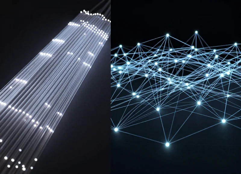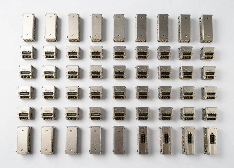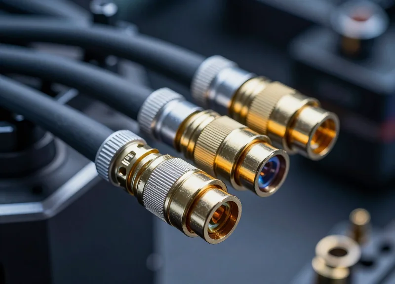
As modern warfare shifts toward data-centric operations, the demand for high-speed, reliable data transmission in the field has never been higher. Military-grade optical interconnects provide the backbone for these systems, offering immunity to EMI and massive bandwidth. This article explores the technical nuances that separate mil-spec components from commercial-grade hardware, addressing how they overcome the challenges of vibration, temperature, and contaminants.
Defining Military Grade: The Gold Standard of Reliability
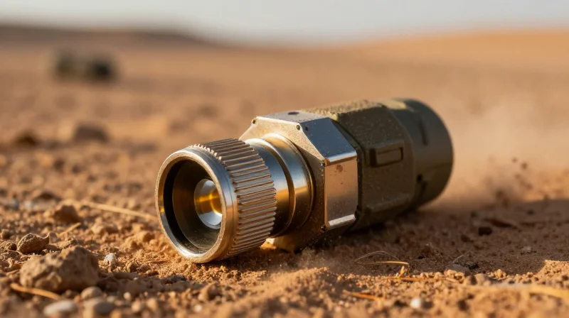
A military-grade optical interconnect is a specialized fiber optic assembly engineered to maintain absolute signal integrity under environmental stresses that would immediately compromise standard commercial hardware. Unlike commercial-grade optics optimized for cost and density in climate-controlled data centers, military interconnects are built for survival in the most unforgiving theaters of operation—from the vacuum of space and high-altitude avionics to the high-vibration and corrosive environments of naval vessels and ground combat vehicles. These components serve as the central nervous system for mission-critical systems where a single decibel of signal loss can result in catastrophic failure.
The MIL-SPEC Benchmark: Defining Ruggedness
The distinction between 'ruggedized' and 'military-grade' is often found in compliance with specific United States Military Standards (MIL-SPEC). These standards, such as MIL-DTL-38999 for circular connectors or MIL-PRF-28876 for maritime applications, dictate everything from the thickness of the plating to the specific polymer used in the seals. These benchmarks ensure that the interconnects can handle rapid decompression, immersion in hydraulic fluids, and the intense electromagnetic interference (EMI) common in modern electronic warfare environments.
| Specification | Commercial Standard (COTS) | Military Grade (MIL-SPEC) |
|---|---|---|
| Operating Temperature | 0°C to +70°C (Commercial) or -40°C to +85°C (Industrial) | Extreme ranges from -55°C to +125°C or higher |
| Vibration Resistance | Minimal (designed for static racks) | High-G random vibration per MIL-STD-810 |
| Mechanical Shock | Standard handling drops | 300G+ peak acceleration survivability |
| Coupling Mechanism | Plastic latches or friction fit | Triple-start threaded or bayonet locking with anti-decoupling features |
| Fluid Resistance | None/Moisture resistant | Resistant to JP-8 fuel, hydraulic fluids, and de-icing agents |
Reliability as a Design Philosophy
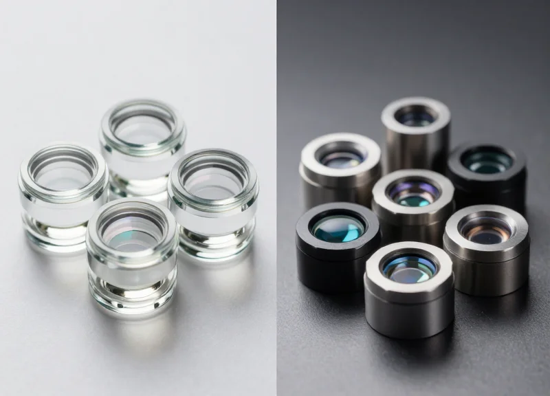
Military interconnect design focuses on 'reliability-by-design' rather than mere performance. This involves the use of specialized ferrule materials, such as ceramic zirconia or stainless steel, and expanded beam technology. Expanded beam connectors are particularly notable in military applications; they utilize lenses to expand the light signal across a larger area at the interface, making the connection significantly less sensitive to dust, debris, and vibration that would otherwise terminate a physical contact (PC) fiber connection in the field.
Common Questions Regarding Military Standards
- Is 'Military Grade' just a marketing term?
No. Authentic military-grade interconnects must undergo 'Qualification Test Reports' (QTR) which involve destructive testing of samples to prove they meet the rigorous survivability requirements of MIL-STD-810 or specific DLA requirements. - Why is there such a significant price difference compared to commercial fiber?
The cost reflects specialized materials (e.g., aerospace-grade aluminum, gold plating), extensive batch testing for traceability, and specialized manufacturing processes required to meet hermetic sealing and vibration damping standards. - Can commercial-off-the-shelf (COTS) parts be used in military systems?
Sometimes, through a process called 'COTS-Plus,' where commercial parts are screened and upgraded for better reliability, but they rarely match the full environmental envelope of a dedicated MIL-SPEC part.
Key Technical Specifications and MIL-SPEC Standards
Military-grade optical interconnects are defined by a hierarchy of MIL-SPEC standards that mandate specific mechanical durability, thermal stability, and optical precision to ensure mission success in environments that would cause commercial hardware to fail. These specifications act as the blueprint for interoperability and survivability across the global defense supply chain.
The Triad of Military Optical Standards
The landscape of military fiber optics is dominated by three primary standards that address different layers of the interconnect assembly. MIL-DTL-38999 is the gold standard for connector shells, offering a rugged, circular housing that can accommodate various inserts. MIL-PRF-29504 focuses on the optical termini themselves, ensuring that the 'pins' and 'sockets' maintain sub-micron alignment. For deployments in high-contamination zones, MIL-DTL-83526 provides specifications for expanded beam technology, which uses lenses to widen the light path and mitigate the effects of dust and debris.
| Standard | Component Focus | Primary Advantage | Typical Application |
|---|---|---|---|
| MIL-DTL-38999 | Circular Connector Shells | Extreme vibration and EMI/RFI shielding | Avionics and shipboard systems |
| MIL-PRF-29504 | Optical Termini (PC) | Low insertion loss and high precision | Static high-bandwidth data links |
| MIL-DTL-83526 | Expanded Beam Connectors | Exceptional debris and soil resistance | Tactical field deployments |
| ARINC 801 | Aero-Optical Interconnects | High-density packaging and pull-proof design | Military and commercial flight decks |
Environmental and Optical Performance Thresholds
Standardization extends beyond the form factor to the physical performance envelope. Military specifications require components to operate reliably across a temperature range of -55°C to +125°C. Furthermore, these interconnects must survive hundreds of mating cycles and resist corrosive elements like salt spray and hydraulic fluids. From an optical perspective, the standards often dictate an insertion loss of less than 0.75 dB and a return loss greater than 40 dB for single-mode applications to ensure signal integrity over long-distance battlefield networks.
MIL-SPEC Frequently Asked Questions
- Why is MIL-DTL-38999 Series III the preferred shell for fiber?
Series III utilizes a triple-start thread and a self-locking mechanism that prevents the connector from backing off under high-frequency vibration, which is critical for maintaining fiber alignment. - How does MIL-PRF-29504 handle mechanical shock?
These termini are designed with precision-calibrated internal springs that maintain physical contact between fiber ends even during explosive shocks or heavy G-loads. - What is the difference between physical contact and expanded beam standards?
Physical contact (MIL-PRF-29504) involves fiber ends touching for maximum signal; expanded beam (MIL-DTL-83526) uses lenses to bridge a gap, trading slightly higher signal loss for much greater immunity to dirt.
The Physics of Ruggedization: Materials and Housing
The Physics of Ruggedization: Materials and Housing
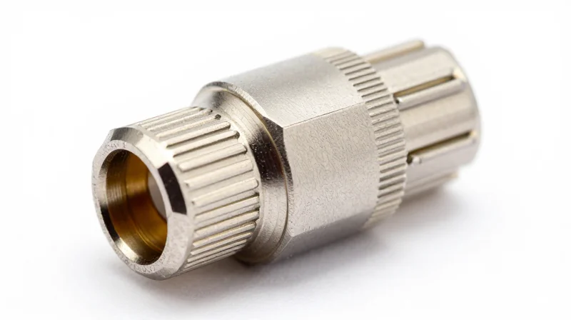
Ruggedization is the process of ensuring that the delicate sub-micron alignment of optical fibers is maintained despite the presence of external kinetic energy, thermal cycling, and chemical degradation. In military-grade interconnects, the housing is more than just a container; it is a precision-engineered barrier designed to dissipate mechanical shock and neutralize galvanic corrosion that would otherwise compromise the structural integrity of the link.
Specialized Alloys for Defense Environments
The choice of base metal is driven by the operational theater. For naval and maritime applications, Marine Bronze (typically Nickel Aluminum Bronze) is the preferred alloy. Its inherent resistance to biofouling and its ability to form a protective oxide film make it immune to the high-salinity conditions that would destroy standard aluminum connectors. For ground-based and aerospace applications where weight-to-strength ratios are critical, high-grade Stainless Steel or Aluminum alloys with specialized tempers are utilized.
| Material | Key Property | Primary Application |
|---|---|---|
| Marine Bronze (C63000) | Superior corrosion resistance and natural lubricity. | Submarines, Surface Ships, Coastal Defense. |
| Stainless Steel (316L) | High tensile strength and chemical resistance. | CBRN Environments, Heavy Machinery, Ground Vehicles. |
| Aluminum (6061-T6) | Low weight with high structural rigidity. | Avionics, Man-portable Gear, Satellites. |
Surface Engineering and Protective Platings
Surface treatments are applied to base alloys to provide an additional layer of environmental defense and to ensure electrical continuity for EMI/RFI shielding. While Olive Drab Cadmium has long been the MIL-SPEC standard for its exceptional corrosion resistance and self-healing properties, environmental regulations have accelerated the adoption of Zinc-Nickel (ZnNi) and Electroless Nickel. These platings prevent the formation of 'white rust' and ensure that the shell-to-shell conductivity remains within the millivolt requirements specified by MIL-DTL-38999 standards.
FAQ: Material Science in Optical Ruggedization
- Why is Marine Bronze used instead of Stainless Steel in naval optics?
Marine Bronze is non-sparking and has better resistance to 'crevice corrosion' in stagnant seawater compared to most stainless steel grades. It also resists the growth of marine organisms which can seize moving parts in connectors. - What is the role of passivated Stainless Steel?
Passivation is a chemical treatment that removes free iron from the surface of the steel, maximizing its natural corrosion resistance. This is vital for interconnects exposed to the acidic environments of engine bays or chemical cleaning agents. - How does housing material affect optical performance?
The Coefficient of Thermal Expansion (CTE) of the housing must be managed to ensure that as the temperature changes, the internal ferrules do not shift, which would cause signal loss or physical damage to the fiber faces.
Optical Performance in High-Vibration Environments
Optical Performance in High-Vibration Environments
In military applications, optical interconnects must provide unwavering signal stability while subjected to the intense mechanical stresses of jet engines, rotorcraft transmissions, and tracked vehicle movement. Unlike commercial fiber optics, which may suffer from 'signal flickering' or permanent misalignment under stress, military-grade components are engineered to keep Insertion Loss (IL) and Return Loss (RL) within strict tolerances—typically <0.3 dB and >40 dB respectively—regardless of external G-forces or resonance.
Mitigating the Piston Effect through Spring-Loaded Termini
The primary challenge in high-vibration environments is the 'piston effect,' where the fiber optic ferrule moves longitudinally within its housing, potentially creating an air gap between fiber end-faces. To counter this, MIL-PRF-29504 compliant termini utilize heavy-duty, corrosion-resistant stainless steel springs. These springs provide a constant axial force that ensures the polished fiber tips remain in Physical Contact (PC) at all times, preventing the Fresnel reflections that occur when an air gap is introduced.
| Feature | Physical Contact (PC) Termini | Expanded Beam (EB) Technology |
|---|---|---|
| Vibration Resistance | Relies on high spring force to maintain contact. | Inherently resistant due to non-contacting interface. |
| Typical Insertion Loss | Very Low (0.2 dB to 0.5 dB) | Moderate (1.0 dB to 2.0 dB) |
| Misalignment Tolerance | Low; requires sub-micron precision. | High; expanded light path is less sensitive to jitter. |
| Primary Use Case | High-bandwidth, low-loss data links. | Tactical deployments and extreme shock environments. |
Precision Alignment and Material Stability
Beyond spring tension, the choice of materials for alignment sleeves is critical. Military interconnects often use split-zirconia ceramic or phosphor bronze sleeves. Zirconia is preferred for its high elastic modulus and thermal stability, which ensures that the radial alignment of the fiber cores (often as small as 9 microns for single-mode fiber) remains constant even when the connector body is vibrating at frequencies up to 2,000 Hz.
- How does vibration affect Return Loss?
Vibration can cause micro-separations between fiber faces. If an air gap forms, light reflects back toward the source, causing high return loss and potentially damaging laser transmitters or increasing bit error rates. - What is the advantage of Expanded Beam (EB) in high-shock scenarios?
EB technology uses lenses to expand the light beam to many times its original diameter. Because the two halves of the connector do not physically touch, mechanical vibration does not cause wear on the fiber faces, and small lateral shifts have negligible impact on the signal. - How is vibration performance validated?
Components undergo testing per MIL-STD-1344, Method 2005, which involves monitoring for optical 'discontinuities' (signal loss exceeding a specific threshold for more than 1 microsecond) during swept-frequency vibration cycles.
Physical Contact vs. Expanded Beam Technology
Physical Contact vs. Expanded Beam Technology
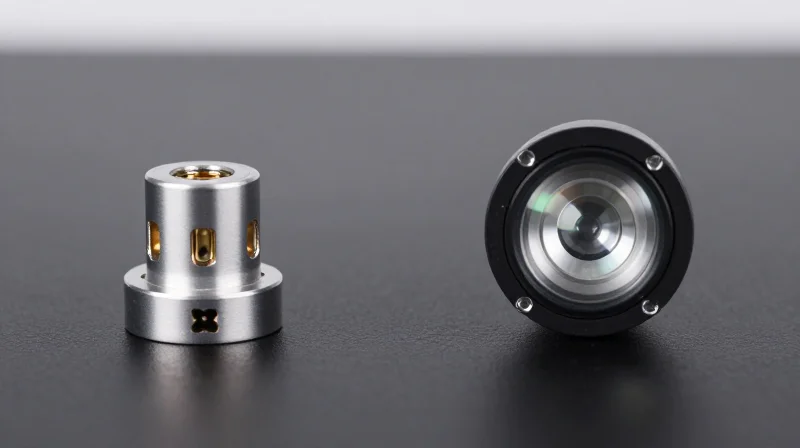
The choice between Physical Contact (PC) and Expanded Beam (EB) technology represents the fundamental trade-off in military fiber optics: the pursuit of absolute signal precision versus the necessity for field-hardened reliability. While PC connectors offer superior optical performance in controlled environments, EB technology has become the gold standard for tactical deployments where mud, dust, and moisture are unavoidable.
The Mechanics of Physical Contact (PC)
Physical Contact connectors utilize highly polished ceramic or metal ferrules to bring two fiber cores into direct, physical alignment. By minimizing the air gap between the glass surfaces, PC interfaces achieve extremely low insertion loss (typically <0.3 dB) and high return loss. However, because the light path is only 9 microns wide in single-mode fiber, a single speck of dust can completely block the signal or permanently damage the fiber end-face during mating.
The Mechanics of Expanded Beam (EB)
Expanded Beam technology utilizes spherical or aspheric lenses to diverge the light from the fiber core into a beam with a diameter many times larger than the original. This expanded light path travels across a small air gap to a receiving lens that refocuses the light back into the opposing fiber. Because the light is distributed over a larger surface area, a particle of dust that would catastrophically fail a PC connector only causes a negligible increase in attenuation in an EB interface.
| Feature | Physical Contact (PC) | Expanded Beam (EB) |
|---|---|---|
| Insertion Loss | Very Low (0.2 - 0.5 dB) | Moderate (1.0 - 2.0 dB) |
| Contamination Sensitivity | Extremely High | Very Low |
| Cleaning Requirement | Microscopic Inspection Required | Simple Water Rinse/Wipe |
| Mating Cycles | 500 - 1,000 | 1,000 - 5,000+ |
| Primary Application | Fixed Shelters, Avionics | Tactical Field Deployments |
Operational Advantages in the Field
The primary driver for EB adoption in military interconnects is 'survivability' over 'spec-sheet perfection.' In a combat or disaster recovery zone, technicians cannot perform microscopic inspections or use specialized cleaning solvent kits. EB connectors allow for 'wash-and-wear' maintenance; a dirty connector can often be restored to operational status simply by rinsing it with water and wiping it with a cloth, ensuring mission-critical communications remain active in the most punishing conditions.
Common Questions on Optical Interfaces
- Can PC and EB connectors be mated together?
No. The internal architectures are fundamentally different. Interoperability requires a specialized media converter or a hybrid patch cable to bridge the two technology types. - Is Expanded Beam always better for military use?
Not necessarily. For permanent installations inside aircraft or ships where the environment is controlled, PC connectors are preferred for their lower power loss and higher bandwidth density. - How does vibration affect these two types?
PC connectors are more susceptible to 'fretting' (surface wear) under high vibration. EB connectors, utilizing a non-contacting optical interface, are generally more immune to vibration-induced signal degradation.
Environmental Sealing and Thermal Management
Environmental Sealing and Thermal Management
Military-grade optical interconnects are engineered to maintain signal integrity in environments where consumer-grade equipment would fail instantaneously, relying on hermetic sealing and thermal stabilization techniques. These components must withstand pressure differentials, moisture ingress, and the physical expansion or contraction of materials across a wide temperature spectrum, typically ranging from -55°C to +125°C. By integrating advanced material science with precision mechanical design, these interconnects protect delicate glass fibers from the corrosive and mechanical stresses found in modern theaters of operation.
Ingress Protection: IP67, IP68, and Hermetic Sealing
To prevent moisture, salt spray, and particulate contamination from reaching the fiber interface, military connectors adhere to stringent Ingress Protection (IP) ratings. These ratings are achieved through the use of fluorosilicone O-rings, specialized gaskets, and precision-machined threads that create a vacuum-tight seal. In high-altitude or undersea applications, hermetic sealing is often required to prevent gas exchange and maintain internal pressure equilibrium.
| Sealing Rating | Environmental Protection Level | Primary Military Use Case |
|---|---|---|
| IP67 | Dust-tight and protected against temporary submersion (1m for 30 min). | Tactical field-deployable communication kits. |
| IP68 | Dust-tight and protected against continuous submersion under pressure. | Maritime sensors and amphibious vehicle electronics. |
| Hermetic | Gas-tight seal (usually <1x10^-7 cm3/s of Helium). | Space-bound avionics and high-altitude UAV sensors. |
Thermal Resilience and Material Stability
The primary challenge in extreme temperature environments is the Coefficient of Thermal Expansion (CTE). As temperatures swing between the extremes of -55°C and +125°C, the different materials within a connector—metal shells, ceramic ferrules, and plastic housings—expand and contract at varying rates. This can lead to micro-bending of the fiber, which increases insertion loss. Military interconnects mitigate this by using CTE-matched materials and specialized optical adhesives that remain flexible at cryogenic temperatures while resisting outgassing at high heat.
- Why is moisture particularly dangerous for military fiber optics?
Beyond simple signal attenuation, moisture can cause 'stress corrosion' in glass fibers and lead to ice formation at low temperatures, which exerts mechanical pressure that can physically fracture the fiber. - How do these interconnects handle rapid temperature cycling?
They are tested through hundreds of thermal shock cycles to ensure that the internal alignment of the ferrules and the integrity of the seals do not degrade over the system's lifecycle. - What role does plating play in environmental protection?
Specialized finishes like Nickel-PTFE or Zinc-Nickel are applied to the connector shells to provide over 500 hours of salt spray resistance, preventing the galvanic corrosion that compromises the seal.
Applications: From UAVs to Naval Command Centers
Applications: From UAVs to Naval Command Centers
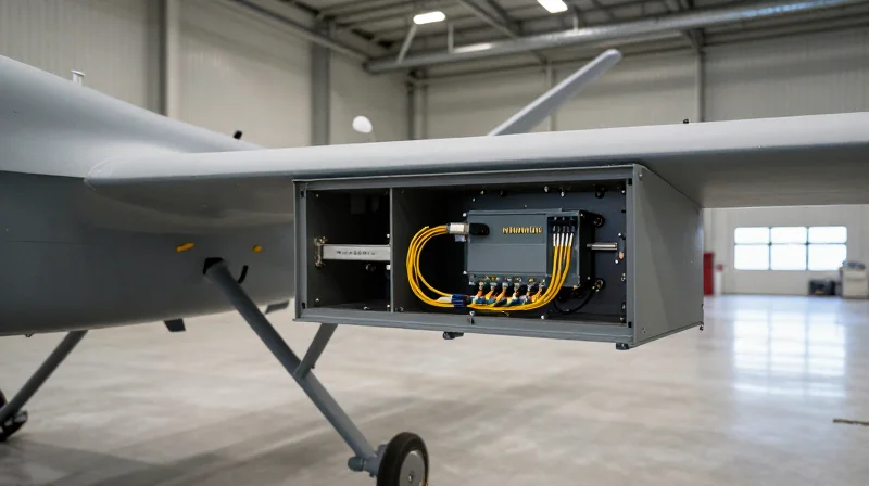
Military-grade optical interconnects function as the high-capacity central nervous system for modern multi-domain operations, providing the essential throughput needed for real-time situational awareness and secure data transmission. These systems are indispensable in environments where traditional copper-based solutions are rendered obsolete by electromagnetic interference (EMI), signal degradation over distance, or excessive weight constraints.
Aerial Dominance: UAVs and Airborne Intelligence
In Unmanned Aerial Vehicles (UAVs) and manned reconnaissance aircraft, the primary challenge is Size, Weight, and Power (SWaP). Optical interconnects allow for the integration of high-definition 4K infrared sensors, LiDAR, and Synthetic Aperture Radar (SAR) without adding the heavy shielding required by copper cables. By utilizing high-density MT-ferrule connectors, engineers can route hundreds of gigabits of data through a single, lightweight interface, ensuring that intelligence gathered at the edge is processed and transmitted with zero latency.
Maritime Resilience: Shipboard and Submarine Systems
Naval command centers and shipboard environments demand interconnects that can survive extreme mechanical shock, high-frequency vibration, and the corrosive effects of salt-laden air. Fiber optic backbones on modern destroyers and carriers facilitate secure communications between sonar arrays and the Combat Information Center (CIC). Because light signals do not emit radiation, optical interconnects provide an inherent layer of security against electronic eavesdropping, a critical requirement for classified naval data networks.
| Application Platform | Primary Constraint | Preferred Interconnect Feature |
|---|---|---|
| Small UAVs / Drones | Weight and Payload Capacity | Small-form-factor MT ferrules |
| Naval Vessels | Corrosion and Vibration | Salt-fog resistant plating (Nickel/PTFE) |
| Ground Tactical Units | Field Contamination | Expanded Beam (HMA) Technology |
| Radar Installations | EMI/RFI Interference | Dielectric non-conductive cabling |
Tactical Ground Networks and Deployable Comms
On the battlefield, tactical optical networks are deployed rapidly to connect mobile command posts to satellite uplinks and remote sensor arrays. These systems rely heavily on Expanded Beam technology, which widens the light path across the connector interface. This design ensures that even if a connector is dropped in mud or dust, the signal remains intact, allowing ground troops to maintain high-speed connectivity in the world's most inhospitable theaters of operation.
- Why is fiber preferred over copper in naval ships?
Fiber offers immunity to electromagnetic interference from massive radar systems and reduces the risk of sparking in volatile environments, while also significantly reducing the weight of the vessel's cabling infrastructure. - How do UAVs benefit from optical interconnects?
They allow for the transfer of massive sensor data streams (like high-res video and radar) using ultra-lightweight components, directly improving the aircraft's fuel efficiency and flight duration. - Can optical interconnects handle the shock of missile launches?
Yes, military-grade connectors are designed with specialized locking mechanisms and spring-loaded ferrules that maintain physical contact or beam alignment even under high-G shock events.
SWaP-C Optimization in Interconnect Design
The SWaP-C Mandate in Modern Defense Systems
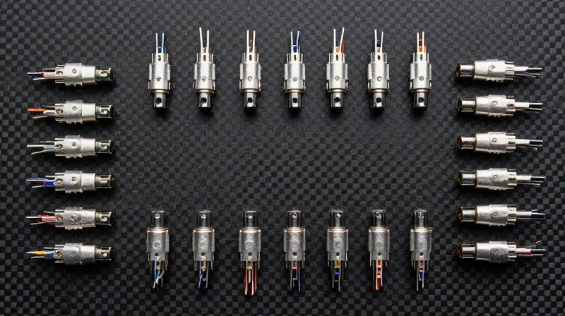
SWaP-C optimization—balancing Size, Weight, Power, and Cost—is the primary design philosophy governing modern military-grade optical interconnects. As defense platforms transition to more complex, data-heavy architectures, the physical layer must evolve to support massive bandwidth without increasing the vehicle's or the soldier's payload. Optical fiber is inherently advantageous in this regard, offering a significantly higher bandwidth-to-weight ratio compared to traditional copper cabling. By replacing heavy shielded copper bundles with lightweight glass fibers, engineers can achieve up to a 90% reduction in cable weight, which directly translates to improved fuel efficiency for aircraft and increased mission duration for unmanned aerial vehicles (UAVs).
Advancements in Miniaturized Circular Connectors
The push for miniaturization has led to the development of high-density circular connectors that pack more optical channels into smaller shells. Traditional MIL-DTL-38999 connectors are being augmented or replaced by micro-circular and nano-miniature formats. These connectors utilize advanced precision ceramics and composite housings to maintain alignment and durability at a fraction of the size. This miniaturization is critical for 'soldier-worn' electronics and compact gimbal-mounted sensors where every millimeter of space is contested.
| Metric | Legacy Copper Interconnects | Optimized Military Optical Interconnects |
|---|---|---|
| Weight | High (Heavy shielding required) | Very Low (Lightweight glass/polymers) |
| Size/Diameter | Thick, rigid bundles | Small, flexible high-density fibers |
| Power Consumption | Higher loss over distance | Negligible loss; no active cooling needed |
| Data Capacity | Limited by EMI and distance | Near-infinite scalability via WDM |
Addressing Power and Life-Cycle Costs
Beyond size and weight, optical interconnects contribute to 'Power' optimization by reducing the need for signal repeaters and heavy thermal management systems. Since fiber does not generate heat or succumb to electromagnetic interference (EMI), the surrounding hardware can be simplified. The 'Cost' element of SWaP-C is addressed through the longevity of the components. Military-grade optics are designed for multi-decade lifecycles, using modular 'termini' (contacts) that can be individually replaced if damaged, rather than discarding the entire connector assembly.
- How does fiber improve power efficiency?
Optical signals experience minimal attenuation over long distances compared to copper, reducing the power required for signal amplification and eliminating the need for bulky EMI shielding. - Why are circular connectors preferred for miniaturization?
Circular designs offer the best strength-to-weight ratio for locking mechanisms and provide natural environmental sealing, which is essential when shrinking components for tactical use. - Is optical fiber more expensive than copper in SWaP-C terms?
While initial material costs can be higher, the total cost of ownership is lower due to reduced fuel costs (from weight savings) and higher reliability in harsh environments.
Future Trends: 100G and Beyond in Defense

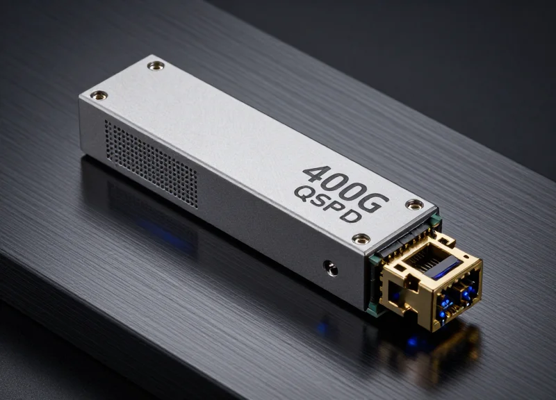
The next frontier for military-grade optical interconnects lies in the transition from 10G and 40G architectures to 100G, 400G, and even 800G throughput. This evolution is driven by the massive data requirements of real-time sensor fusion, high-definition persistent surveillance, and edge-computing AI. To achieve these speeds without compromising the ruggedness required for defense, the industry is pivoting toward silicon photonics and ultra-high-density fiber packaging that integrates directly with the system-on-chip (SoC) architecture.
Silicon Photonics: Redefining Chip-to-Chip Communication
Silicon photonics (SiPh) is the primary catalyst for 100G+ speeds in military environments. By integrating optical components like modulators and detectors onto a standard silicon substrate, manufacturers can reduce the distance electrical signals must travel before conversion. This results in significant SWaP-C advantages, including lower power consumption and reduced heat generation—critical factors in enclosed environments like electronic warfare (EW) pods and compact UAV avionics.
Ultra-High-Density Multi-Fiber Ferrules
To support 100G and 400G protocols, the density of fiber within a single connector must increase. The defense sector is moving away from traditional single-ferrule connectors toward multi-fiber push-on (MPO) and Mechanical Transfer (MT) ferrules that can support 12, 24, or 48 fibers in a single interface. However, unlike commercial data centers, military applications utilize expanded beam technology within these ferrules to ensure that dust and vibration do not cause catastrophic signal loss during high-speed transmission.
| Feature | Current Gen (10G/40G) | Next Gen (100G/400G+) |
|---|---|---|
| Signal Architecture | Discrete Optical Transceivers | Integrated Silicon Photonics (SiPh) |
| Fiber Density | Duplex (2 fibers) | MPO/MT Ferrules (12-48 fibers) |
| Connector Type | Physical Contact (PC/APC) | Ruggedized Expanded Beam MT |
| Power Efficiency | ~30-50mW per Gbps | <5mW per Gbps (with SiPh) |
Future Technical Challenges and FAQ
- Will 100G fiber survive high-vibration environments?
Yes, through the use of ruggedized MT ferrules and specialized strain-relief housings designed to maintain alignment even under the G-forces experienced in fighter jets and missile systems. - How does Silicon Photonics handle extreme temperatures?
Modern SiPh designs include integrated thermal stabilization and use materials with low coefficients of thermal expansion to maintain optical alignment from -55°C to +125°C. - Is the defense industry ready for 400G bandwidth?
While current tactical hardware is primarily 10G/40G, the shift to AI-driven battle management systems makes 400G a necessity for future-proofing naval command centers and ISR hubs.
Military-grade optical interconnects are the unsung heroes of modern defense infrastructure, providing the resilient connectivity required for real-time decision-making. As data requirements continue to scale, choosing the right interconnect becomes a strategic imperative. To learn more about selecting the ideal ruggedized optical solution for your specific application, contact our engineering team for a consultation today.