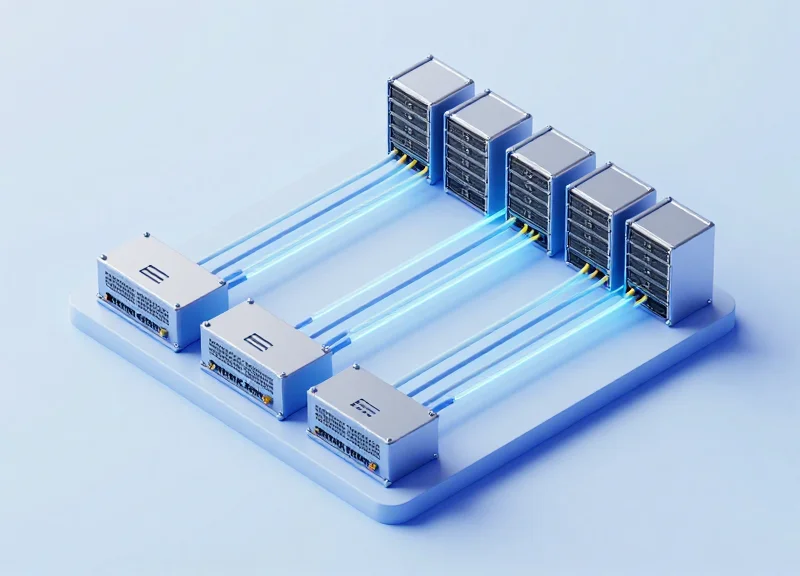
As hyperscale data centers pivot toward 400G to meet the demands of AI and machine learning, selecting the right optical interface is a multi-million dollar decision. While 400G SR8 offers a robust path for short-reach applications, it faces stiff competition from single-mode alternatives. This guide breaks down the performance metrics and financial implications for network architects and IT decision-makers.
The Rise of 400G: Navigating the Optical Interface Landscape
The Rise of 400G: Navigating the Optical Interface Landscape
The transition to 400G Ethernet is no longer a future-looking roadmap item but a baseline requirement for modern cloud networking, driven by the exponential growth of East-West traffic and the data-intensive nature of distributed computing. This shift represents a fundamental architectural pivot where cloud operators must choose between multiple optical standards—SR8, DR4, and FR4—each offering distinct advantages in terms of power consumption, reach, and total cost of ownership (TCO) depending on the specific tier of the data center fabric.
Decoding the 400G Interface Standards
Unlike the relatively uniform transition from 10G to 40G, 400G introduces a diverse array of form factors and modulation techniques. The primary distinction lies in how the 400Gbps signal is delivered across the physical medium. While 400G SR8 (Short Reach 8-lane) relies on parallel multimode fiber (MMF), alternatives like DR4 and FR4 utilize single-mode fiber (SMF) with varying laser configurations and reaches. These differences dictate not just the hardware cost of the transceiver, but the long-term viability of the cabling infrastructure.
| Interface Standard | Fiber Type | Max Reach | Lane Configuration | Connector Type |
|---|---|---|---|---|
| 400G SR8 | Multimode (OM4) | 100m | 8 x 50G PAM4 | MPO-16 / MPO-24 |
| 400G DR4 | Single-mode (OS2) | 500m | 4 x 100G PAM4 | MPO-12 |
| 400G FR4 | Single-mode (OS2) | 2km | 4 x 100G CWDM | LC Duplex |
Strategic Considerations for Cloud Scaling
- Why is 400G SR8 often preferred for top-of-rack (ToR) applications?
SR8 is the most cost-effective solution for short-range connections under 100 meters, leveraging mature VCSEL laser technology and lower-cost multimode optics compared to single-mode alternatives. - When should cloud operators pivot from SR8 to DR4 or FR4?
The shift to DR4 is necessary when reaching beyond 100 meters or when a 4x100G breakout strategy is required for spine-leaf connectivity. FR4 is reserved for longer 2km spans where fiber conservation is critical, as it uses multiplexing to run over a single pair of fibers. - How does PAM4 modulation impact these interfaces?
All three standards utilize PAM4 (Pulse Amplitude Modulation 4-level) to double the data rate per clock cycle compared to NRZ, though the implementation complexity varies between the 8-lane SR8 and 4-lane SMF options.
Technical Architecture: Decoding the 400G SR8 Standard
Technical Architecture: Decoding the 400G SR8 Standard
The 400G SR8 (Short Range, 8-lane) standard represents a parallel multimode optical architecture designed to provide high-density, short-reach connectivity for hyperscale data centers. By utilizing eight discrete fiber pairs—each carrying 50Gbps or 100Gbps—the SR8 standard achieves an aggregate throughput of 400Gbps over distances up to 100 meters. This 'wide' architectural approach favors the use of Vertical-Cavity Surface-Emitting Lasers (VCSELs), which are significantly more cost-efficient than the single-mode silicon photonics or DML lasers required for standards like DR4 or FR4.
The 8-Lane Parallel Multimode Mechanism
Unlike the 4-lane design of SR4 or the wavelength-multiplexed approach of FR4, SR8 relies on spatial multiplexing across 16 fibers (8 for transmit, 8 for receive). This usually necessitates an MPO-16 or MPO-24 connector. The primary advantage of this architecture in cloud environments is its support for high-radix breakout configurations, allowing a single 400G port to be split into eight 50G connections for server-level access or leaf-spine interconnects.
PAM4 Modulation and the Evolution of Electrical Lanes
The transition to 400G SR8 marks a shift from traditional NRZ (Non-Return to Zero) signaling to 4-level Pulse Amplitude Modulation (PAM4). PAM4 allows for two bits of information to be transmitted per symbol period, effectively doubling the data rate without increasing the required optical bandwidth. Furthermore, the SR8 architecture is evolving from 50G PAM4 electrical lanes (8x50G) to 100G PAM4 lanes (4x100G or 8x100G in 800G contexts). This evolution simplifies the Digital Signal Processor (DSP) within the module, reducing both latency and power consumption as the electrical-to-optical lane mapping becomes 1:1.
| Feature | SR8 Specification |
|---|---|
| Modulation | PAM4 (Pulse Amplitude Modulation 4-level) |
| Interface/Connector | MPO-16 or MPO-24 |
| Lane Configuration | 8 Lanes (Transmit/Receive) |
| Fiber Type | OM3/OM4/OM5 Multimode Fiber |
| Max Distance | 70m (OM3) / 100m (OM4/OM5) |
| Laser Source | 850nm VCSEL |
Architectural FAQs
- Why does SR8 use 8 lanes instead of 4?
Using 8 lanes allows for 50G per lane, which utilizes more mature and lower-cost 850nm VCSEL technology compared to the higher-frequency components required for 100G-per-lane designs. - Is SR8 backward compatible?
While SR8 modules can often breakout to legacy 50G speeds, the physical connector (MPO-16) differs from the MPO-12 used in 100G SR4, requiring specific cabling adapters for physical layer interoperability. - How does PAM4 impact signal integrity in SR8?
PAM4 is more sensitive to noise than NRZ. Therefore, SR8 architecture relies heavily on Forward Error Correction (FEC) within the host system and the module's DSP to maintain an acceptable bit error rate (BER).
Latency Benchmarks: SR8 in Low-Latency Environments
Latency Benchmarks: SR8 in Low-Latency Environments
In high-performance computing (HPC) and artificial intelligence (AI) fabrics, every nanosecond counts. The 400G SR8 standard, utilizing multimode fiber (MMF), maintains a competitive edge in latency by minimizing the need for complex digital signal processing (DSP) and aggressive error correction found in longer-reach single-mode optics. For short-reach interconnects within a single row or rack, SR8 provides a deterministic latency profile that is often superior to DR4 or FR4 alternatives because it avoids the overhead associated with the more complex optical components required for single-mode transmission.
Propagation Delay and Media Differences
The physics of light through glass varies slightly between fiber types. Multimode fibers (OM4/OM5) used by SR8 have a refractive index that allows for marginally faster light propagation than standard G.652 single-mode fiber over short distances. While the difference is measured in picoseconds per meter, when compounded across massive AI training clusters with thousands of links, these differences contribute to the overall tail latency of the network fabric. SR8's parallel architecture also ensures that signal skew is kept to a minimum by utilizing eight dedicated lanes of 50G (PAM4).
| Metric | 400G SR8 (Multimode) | 400G DR4 (Single-mode) | 400G FR4 (Single-mode) |
|---|---|---|---|
| Fiber Type | OM4 / OM5 | G.652 / G.657 | G.652 / G.657 |
| DSP Complexity | Low to Moderate | Moderate | High (CWDM) |
| Max Distance | 100m | 500m | 2km |
| Estimated Processing Delay | ~95 - 110 ns | ~110 - 125 ns | ~130 - 150 ns |
FEC and Signal Processing Overhead
A significant portion of 400G latency stems from the Forward Error Correction (FEC) required to handle PAM4 modulation. SR8 benefits from using the KP4 FEC standard, which is consistent across most 400G interfaces. However, because SR8 operates over shorter distances with higher signal integrity on multimode fiber, the internal DSPs can often operate in lower-power modes with fewer taps, leading to reduced processing latency compared to FR4 interfaces that must compensate for chromatic dispersion and higher insertion loss in the optical path.
- Does SR8 improve HFT performance?
Yes, for intra-data center hops, SR8's reduced processing overhead and physical propagation speed make it a preferred choice for the 'last meter' of high-frequency trading networks where microsecond advantages are critical. - Is the latency difference significant for AI clusters?
In synchronized AI training workloads, reducing tail latency is critical. SR8 helps minimize jitter and delay variance across parallel processing nodes, ensuring faster gradient synchronization. - Can FEC be disabled to further reduce latency?
While possible in some proprietary or non-standard implementations, standard 400G SR8 requires FEC to maintain an acceptable Bit Error Rate (BER) due to the nature of PAM4 signaling.
Power Consumption Profiles: Efficiency in the Rack
The 400G SR8 transceiver serves as the efficiency benchmark for short-reach interconnects, typically consuming 20% to 30% less power than single-mode alternatives like DR4 or FR4. This energy advantage stems primarily from the use of Vertical-Cavity Surface-Emitting Laser (VCSEL) technology, which requires significantly lower bias currents compared to the Externally Modulated Lasers (EML) or Silicon Photonics (SiPh) engines found in single-mode optics. By minimizing the Watts per Gigabit at the transceiver level, data center operators can significantly lower their Power Usage Effectiveness (PUE) and extend the thermal headroom of high-density leaf-spine switches.
Power Draw Comparison: SR8 vs. Single-Mode Standards
Power consumption in 400G modules is a function of the laser driver, the TOSA/ROSA components, and the Digital Signal Processor (DSP). While the DSP consumes a relatively fixed amount of power across different 400G form factors (roughly 4W to 5W), the optical engine creates the performance gap. SR8 utilizes 850nm VCSELs that are inherently more efficient over short distances, whereas DR4 and FR4 require more robust, power-hungry lasers to overcome the higher insertion losses and modulation requirements of single-mode fiber over longer distances.
| Transceiver Type | Typical Power (Watts) | Efficiency (mW per Gbps) | Max Reach |
|---|---|---|---|
| 400G SR8 (VCSEL) | 7.5W - 8.5W | 18.75 - 21.25 | 100m (OM4) |
| 400G DR4 (SiPh/EML) | 9.5W - 10.5W | 23.75 - 26.25 | 500m |
| 400G FR4 (EML/CWDM) | 10.5W - 12.0W | 26.25 - 30.00 | 2km |
Thermal Management and Rack Density
Lower power consumption is not merely an electricity cost concern; it is a critical factor in rack-level thermal management. High-radix switches with 32 or 64 ports of 400G generate substantial heat. By utilizing 400G SR8 modules, the total heat dissipation at the faceplate is reduced by approximately 64W to 96W per switch compared to DR4/FR4 deployments. This reduction allows for better airflow management and lower fan speeds, which indirectly improves the overall PUE by reducing the 'overhead' energy used by the cooling infrastructure.
Efficiency FAQ
- Why does SR8 consume less power than DR4?
SR8 uses 850nm VCSELs which operate at lower current levels and do not require the complex temperature stabilization or high-power modulation circuits needed by the 1310nm lasers in DR4. - How does transceiver power affect PUE?
Transceiver power is part of the 'IT Equipment' load. However, for every Watt consumed by the optic, additional energy is required for cooling. Lowering transceiver power reduces the secondary cooling load, driving down the PUE ratio. - Is the DSP power consistent across these modules?
Mostly, yes. Most 400G modules use similar 7nm or 5nm DSPs to handle PAM4 modulation. The primary differentiator in power remains the optical transmission technology.
Cabling Infrastructure: MPO-16 vs. MPO-12 and LC Connectors
Cabling Infrastructure: MPO-16 vs. MPO-12 and LC Connectors
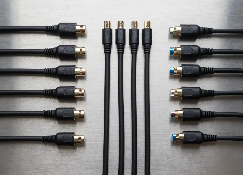
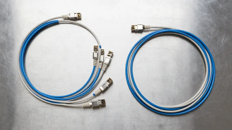
The shift to 400G SR8 introduces a critical inflection point for physical layer architecture, primarily driven by the transition to MPO-16 connectivity. While legacy 100G and 200G solutions often utilized MPO-12 connectors, the 8-lane parallel optics of SR8 require 16 discrete fibers (8 transmit and 8 receive) to maintain 50G PAM4 lanes. This transition forces a choice between the cost-efficiency of multimode transceivers and the increasing complexity of high-fiber-count cabling compared to the duplex LC connections used in single-mode FR4 alternatives.
Comparative Connector Specifications
| Specification | 400G SR8 | 400G DR4 | 400G FR4 |
|---|---|---|---|
| Connector Type | MPO-16 | MPO-12 | LC Duplex |
| Fiber Type | Multimode (OM4/OM5) | Single-mode (OS2) | Single-mode (OS2) |
| Fiber Count | 16 Fibers | 8 Fibers (Active) | 2 Fibers |
| Density Impact | Higher Trunk Volume | Standard MPO Density | Highest Port Density |
| Relative Cable Cost | Low (per meter) | Medium | High (per meter) |
The Density and Management Challenge
Deploying MPO-16 for SR8 impacts data center rack management in two primary ways: cable bulk and patch panel complexity. Because SR8 uses 16 fibers per link, the physical volume of cable required for a top-of-rack (ToR) switch populated with 32 or 64 ports is significantly higher than that of single-mode solutions. For instance, a 400G FR4 link uses a simple LC duplex pair, occupying much less space in the cable trays. However, the cost of OM4 multimode fiber remains substantially lower than OS2 single-mode fiber over short distances, often offsetting the logistical burden of managing thicker cable bundles in small-to-medium-scale AI clusters.
Infrastructure Longevity and Migration Path
- Is MPO-16 backward compatible with MPO-12?
No. The keying and alignment of MPO-16 connectors are offset to prevent accidental mating with MPO-12, meaning SR8 deployments require new trunk cables or specialized transition modules. - How does LC connectivity in FR4 compare to MPO-based systems?
LC duplex connectivity utilized by 400G FR4 is the most space-efficient and simplifies cleaning and testing, but requires more expensive transceivers due to the WDM (Wavelength Division Multiplexing) components inside the module. - Does OM5 fiber provide an advantage for SR8 over OM4?
While OM5 is designed for Shortwave Wavelength Division Multiplexing (SWDM), SR8 does not use multiple wavelengths. Therefore, OM5 offers no performance benefit over OM4 for SR8, though it may provide better future-proofing for SR4.2 architectures.
Ultimately, the choice between MPO-16 and LC-based single-mode infrastructure depends on the planned lifecycle of the data center. While SR8 and MPO-16 offer the lowest immediate transceiver CapEx, the move to single-mode fiber (DR4/FR4) with MPO-12 or LC connectors often provides a more seamless migration path to 800G and 1.6T, where fiber counts per port are expected to be refined through higher-speed individual lane rates.
TCO Analysis: Beyond the Transceiver Price Tag
A true Total Cost of Ownership (TCO) model for 400G data center interconnects must look past the purchase price of the optical module. While the 400G SR8 transceiver is often the most budget-friendly component initially, the cumulative cost of MPO-16 multimode fiber, higher power consumption per bit, and the complexity of cable management in high-density environments often narrow—or even reverse—the cost advantage when compared to single-mode alternatives like DR4 or FR4 over a standard three-to-five-year deployment cycle.
CapEx Comparison: Transceivers vs. Fiber Infrastructure
CapEx is a dual-variable equation involving the active electronics and the passive cabling plant. SR8 utilizes VCSEL technology, which is cheaper to manufacture than the EML or Silicon Photonics lasers used in DR4 and FR4. However, the requirement for 16-fiber MPO-16 cabling for SR8 can increase structured cabling costs by 30-50% compared to the 8-fiber MPO-12 or 2-fiber LC configurations used by single-mode alternatives. In large-scale cloud environments, the savings on transceivers can be entirely consumed by the premium paid for high-density multimode glass and specialized connectors.
| Cost Metric | 400G SR8 (MMF) | 400G DR4 (SMF) | 400G FR4 (SMF) |
|---|---|---|---|
| Relative Module Cost | 1.0x (Baseline) | 1.4x - 1.6x | 1.8x - 2.2x |
| Fiber Type | OM4 MMF (MPO-16) | OS2 SMF (MPO-12) | OS2 SMF (LC Duplex) |
| Fiber Cost per Meter | High | Low | Low |
| Deployment Scalability | Limited (<100m) | High (500m) | Very High (2km) |
OpEx and Sustainability: The Hidden Energy Bill
Operational expenditure is primarily driven by electricity consumption and the resulting heat dissipation. 400G SR8 modules typically consume between 7W and 9W. While this is slightly lower than some early-generation FR4 modules, the massive scale of cloud data centers means that even a 1-watt difference per port can result in thousands of dollars in annual energy savings when factoring in cooling overhead (PUE). Furthermore, single-mode fiber infrastructure provides a more sustainable path for future 800G and 1.6T upgrades, reducing 'rip-and-replace' waste and lowering the long-term carbon footprint of the facility.
TCO FAQ: Financial Planning for 400G
- Is SR8 always the cheapest option for short-reach links?
Not necessarily. If the link distance exceeds 50 meters or requires complex patching, the high cost of MPO-16 trunk cables can quickly exceed the savings gained from cheaper SR8 transceivers. - How does fiber lifespan affect TCO?
Single-mode fiber (OS2) has a significantly longer lifecycle and higher bandwidth ceiling than multimode fiber (OM4). Investing in SMF today for DR4/FR4 deployment often avoids the need for a total cabling overhaul when moving to 800G or 1.6T speeds. - What is the impact of connector density on OpEx?
High-density MPO-16 connectors used by SR8 require more stringent cleaning and maintenance protocols. Contamination in a 16-fiber ferrule is more likely to cause link failure than in a standard LC or MPO-12 connector, increasing troubleshooting man-hours.
SR8 vs. DR4 vs. FR4: A Feature-by-Feature Comparison
Choosing the Right Interface: SR8, DR4, or FR4?
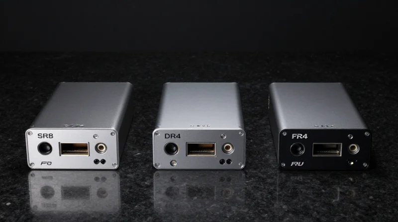
Selecting between 400G SR8, DR4, and FR4 requires balancing the immediate capital expenditure of transceivers against the long-term flexibility and power efficiency of the underlying fiber plant. While SR8 is the dominant choice for ultra-short, intra-rack connections due to its lower power envelope, DR4 and FR4 are critical for inter-rack and spine-leaf connectivity where distance and fiber density become the primary operational constraints.
| Feature | 400G SR8 | 400G DR4 | 400G FR4 |
|---|---|---|---|
| Reach | 100m (OM4/OM5) | 500m | 2km |
| Fiber Type | Multimode (MMF) | Single-mode (SMF) | Single-mode (SMF) |
| Connector Type | MPO-16 | MPO-12 (8 fibers) | LC Duplex |
| Wavelength | 850nm (VCSEL) | 1310nm (SiPh/EML) | CWDM4 (1271-1331nm) |
| Typical Power Consumption | < 8-10W | < 10-12W | < 12W+ |
| Primary Use Case | Top-of-Rack to Server | Leaf-to-Spine / Breakout | Spine-to-Core / Long Reach |
Deployment Considerations and Infrastructure Impact
The transition from multimode to single-mode fiber represents a significant shift in data center design philosophy. SR8 utilizes 16-fiber MPO connectors which can lead to cable congestion, yet its lower power consumption directly reduces the Power Usage Effectiveness (PUE) of the facility. Conversely, FR4 uses standard LC duplex connectors to maximize density and reach, but the internal optical multiplexing components and higher-power lasers increase the thermal load on switch ports, requiring more robust cooling solutions.
- When should I prefer SR8 over DR4?
SR8 is the preferred choice for high-density, intra-rack connections where reach is less than 100 meters and minimizing the initial transceiver purchase cost is the top priority. - Is FR4 better for spine-leaf architectures?
Yes, FR4 is typically better for spine-leaf deployments that exceed 500 meters. Its 2km reach and simple LC cabling infrastructure make it easier to manage than parallel fiber solutions in large-scale facilities. - Does DR4 support breakout modes?
One of the primary advantages of DR4 is its native support for breakout configurations, allowing a single 400G port to connect to four 100G-DR interfaces, which is essential for connecting new switches to existing 100G server NICs.
Cloud Use Cases: When to Deploy 400G SR8
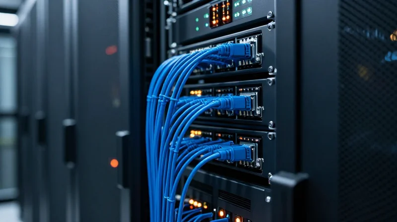
The deployment of 400G SR8 is strategically driven by the need for cost-effective, high-bandwidth interconnects within localized data center zones. While single-mode alternatives excel at distance, SR8 dominates in scenarios where link lengths are minimal, and the budget for optical transceivers is a primary constraint. By utilizing eight lanes of 50G PAM4 over multimode fiber, SR8 provides a robust pathway for cloud providers to scale their internal fabrics without the exponential cost increase associated with long-reach laser components.
Top-of-Rack (ToR) to Leaf Switch Connectivity
In standard leaf-spine architectures, the distance between the Top-of-Rack switch and the leaf switch typically falls within the 30 to 70-meter range. 400G SR8 is the optimal choice for these links because it supports high-density breakout configurations. Cloud operators can use SR8 modules to break out a single 400G port into eight 50G links or two 200G links, allowing for granular bandwidth distribution to servers while maintaining the simplified cabling of an MPO-16 interface.
AI/ML Training Clusters and GPU Fabrics
Artificial Intelligence and Machine Learning workloads require massive east-west traffic capabilities. When GPU accelerators are housed within the same or adjacent racks, 400G SR8 provides the necessary throughput for RDMA (Remote Direct Memory Access) over Converged Ethernet (RoCE) with lower power consumption than single-mode optics. This lower power envelope is critical in AI pods where thermal management is already challenged by high-TDP processors.
| Deployment Scenario | Recommended Standard | Primary Justification |
|---|---|---|
| Intra-Rack (Sub 30m) | DAC or SR8 | Lowest latency and power consumption for localized compute. |
| ToR to Leaf (30m - 100m) | 400G SR8 | Highest ROI for short-reach multimode fiber runs. |
| Leaf to Spine (100m - 500m) | 400G DR4 | Requires single-mode fiber to maintain signal integrity over distance. |
| Inter-Data Center (2km+) | 400G FR4/LR4 | Wavelength multiplexing required for long-haul efficiency. |
Deployment Considerations and FAQs
- Can I use SR8 with existing MPO-12 cabling?
No, 400G SR8 typically requires an MPO-16 or a 2xMPO-12 connector to support the eight-lane transmit and receive architecture. Upgrading to MPO-16 is often necessary for native SR8 support. - Is SR8 more energy efficient than DR4?
Yes, because SR8 uses short-reach VCSEL lasers instead of the more complex silicon photonics or EML lasers found in DR4/FR4, it generally consumes less power per module. - When should I avoid SR8?
Avoid SR8 if your cable runs exceed 100 meters or if your data center is standardized exclusively on single-mode fiber (SMF) to reduce the complexity of managing two different fiber types.
Future-Proofing Your Network: The Path to 800G

Future-Proofing Your Network: The Path to 800G
The transition from 400G to 800G and beyond is fundamentally a race to align electrical lane speeds with optical lane efficiencies. While 400G SR8 relies on eight lanes of 50G PAM4 SerDes, the 800G generation is built upon 100G-per-lane (and soon 200G) architectures. Consequently, future-proofing depends on whether your current physical layer can support the increased signaling rates and whether your cabling infrastructure—specifically MPO-16 versus MPO-12 or duplex fiber—matches the breakout capabilities of next-generation switches.
Scaling the Physical Layer: From 400G to 800G Standards
The evolution path varies significantly depending on the 400G technology deployed today. Organizations using 400G SR8 face a distinct fork in the road: they must eventually migrate to 800G SR8, which utilizes the same fiber count but requires a jump to 100G PAM4 modulation. In contrast, those utilizing single-mode solutions like 400G DR4 have an easier path to 800G DR8, leveraging existing MPO-12 infrastructure for breakout or direct links.
| Current 400G Standard | Logical 800G Successor | Fiber Infrastructure Impact | Upgrade Complexity |
|---|---|---|---|
| SR8 (Multimode) | 800G SR8 | MPO-16 remains compatible; requires OM4/OM5 | Moderate (SerDes upgrade required) |
| DR4 (Single-mode) | 800G DR8 / 2x400G DR4 | High scalability via MPO-12 breakout | Low (Parallel SMF is highly future-proof) |
| FR4 (Single-mode) | 800G FR4 / 2x400G FR4 | Duplex LC remains, but requires CWDM8 or dual optics | High (Optical muxing complexity increases) |
The Role of SerDes Evolution and Form Factors
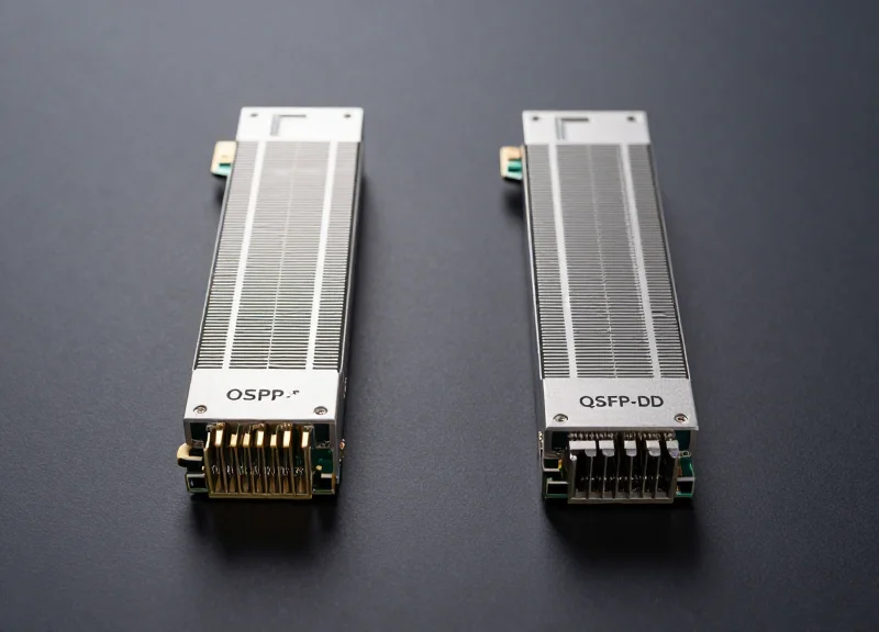
Backward compatibility is largely dictated by the switch ASIC and the transceiver form factor. While QSFP-DD has been the workhorse for 400G, the move to 800G is seeing a stronger push toward OSFP due to its superior thermal management, which is necessary for the higher power consumption of 800G and 1.6T DSPs. If your 400G deployment utilizes QSFP-DD, ensuring your 800G hardware supports QSFP-DD800 is vital for maintaining legacy link connectivity without expensive adapter cables.
- Can 400G SR8 cabling be reused for 800G?
Yes, MPO-16 multimode fiber used for SR8 can be reused for 800G SR8, provided the fiber grade (OM4 or OM5) can handle the 100G-per-lane signaling over the required distance. - Why is DR4 considered more future-proof than SR8?
Single-mode fiber (DR4) offers virtually unlimited bandwidth and supports much longer reaches, making it easier to transition to 800G DR8 or 1.6T solutions without replacing the cable plant. - What is the impact of the 112G SerDes transition?
800G optics require 112G SerDes. If a data center's 400G infrastructure is purely 50G SerDes-based (SR8), they will need to ensure that 800G ports can 'gear down' to support legacy 400G modules or use active electrical cables (AECs).
As the industry looks toward 1.6T, the shift toward co-packaged optics (CPO) or standardized 200G-per-lane signaling will make current 400G choices even more impactful. Early adoption of parallel single-mode fiber (PSM) and high-density connectors like SN or MDC today will significantly reduce the CapEx of these future 'forklift' upgrades.
Selecting the right 400G standard requires balancing immediate performance needs with long-term infrastructure flexibility. While SR8 remains a cost-effective powerhouse for short-reach cloud applications, the evolution toward single-mode optics is accelerating. To determine which solution fits your specific TCO model, consult with our optical networking specialists today for a tailored performance assessment.