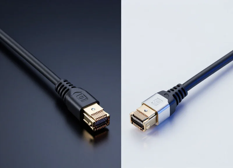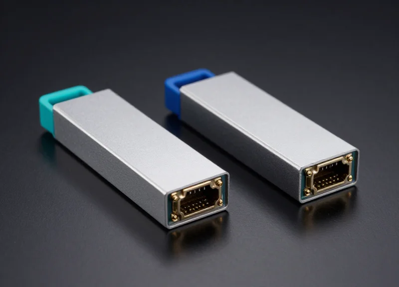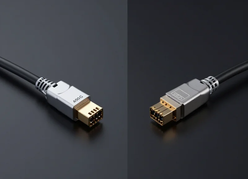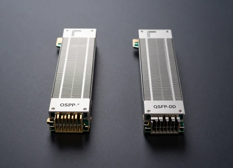
As AI workloads and hyperscale demands explode, 800G networking has moved from the horizon to the rack. This guide breaks down why the OSFP DR8 is a front-runner and how it stacks up against competing standards in the real-world metrics that matter most: power, speed, and cost.
The Shift to 800G: Why the OSFP DR8 Matters Now

The transition to 800G OSFP DR8 is necessitated by a fundamental shift in data center traffic patterns, where traditional 400G architectures can no longer sustain the low-latency, high-throughput requirements of modern AI training clusters. The OSFP DR8 module provides a scalable path forward by doubling the port density and leveraging 100G-per-lane electrical signaling, making it the most viable solution for hyperscale environments looking to minimize complexity while maximizing data throughput.
The AI/ML Catalyst for 800G Adoption
Artificial Intelligence and Machine Learning (ML) workloads involve massive datasets distributed across thousands of GPUs. These GPUs require a backend network (the 'compute fabric') that can handle bursty, high-bandwidth communication with minimal packet loss. While 400G was sufficient for previous generations, Large Language Models (LLMs) now demand the 800G capacity offered by OSFP DR8 to prevent the network from becoming a bottleneck during the gradient synchronization phases of model training.
Thermal and Structural Advantages of the OSFP Form Factor
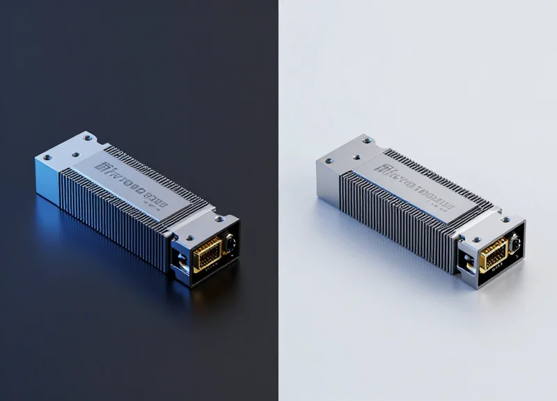
A primary reason the OSFP (Octal Small Form-factor Pluggable) has gained traction over alternatives like QSFP-DD at the 800G level is its superior thermal management. As transceivers consume more power to drive higher speeds, dissipating heat becomes a critical challenge. The OSFP design includes an integrated heat sink, allowing it to handle up to 15-20W of power more effectively, ensuring long-term reliability in the high-density racks typical of AI data centers.
| Feature | 400G DR4 | 800G OSFP DR8 |
|---|---|---|
| Aggregate Bandwidth | 400 Gbps | 800 Gbps |
| Electrical Lane Speed | 50G (PAM4) | 100G (PAM4) |
| Optical Lanes | 4 x 100G | 8 x 100G |
| Typical Power Consumption | 8W - 12W | 14W - 18W |
| Fiber Connector | MPO-12 | MPO-16 (or dual MPO-12) |
Common Questions on 800G Transition
- Why choose DR8 over 2xFR4 or other 800G variants?
The DR8 is preferred for its versatility in breakout applications. It can easily be split into 2x 400G or 8x 100G connections, providing the flexibility needed for connecting leaf switches to various server speeds. - Is OSFP backward compatible with QSFP?
OSFP is not directly backward compatible with the QSFP physical slot due to its larger size; however, adapters exist, and many switch vendors offer ports that can support different form factors via multispeed configurations. - How does 112G SerDes affect the shift?
The move to 112G SerDes allows for 800G throughput using only 8 electrical lanes, matching the 8 optical lanes of the DR8, which simplifies the internal architecture of the transceiver and reduces latency.
Technical Specifications: Unpacking the OSFP DR8 Standard
Technical Specifications: Unpacking the OSFP DR8 Standard
The 800G OSFP DR8 (Data center Reach 8-lane) transceiver is defined by its use of an 8x100G parallel transmission architecture, leveraging 100G PAM4 modulation to achieve a total throughput of 800Gbps. Unlike WDM (Wavelength Division Multiplexing) solutions that combine signals onto a single fiber pair, the DR8 standard utilizes eight distinct optical channels, providing a native breakout capability that is essential for high-density leaf-spine interconnects in modern hyperscale environments.
The 8x100G Parallel Fiber Architecture
The core of the DR8 specification is its reliance on parallel Single Mode Fiber (SMF). By utilizing an MPO-16 or dual MPO-12 connector, the module transmits and receives across 16 fibers (8 Tx and 8 Rx). This design avoids the complexity and heat generation of optical multiplexing components, allowing for lower latency and improved thermal management within the dense OSFP form factor. The 500-meter reach is specifically optimized for intra-datacenter spans, bridging the gap between top-of-rack switches and the core network.
| Parameter | OSFP 800G DR8 Specification |
|---|---|
| Modulation | 100G PAM4 |
| Optical Interface | MPO-16 (APC) |
| Reach | 500 Meters |
| Fiber Type | Single-Mode (SMF) |
| Wavelength | 1310nm |
| Power Consumption | Typically <16W |
Silicon Photonics (SiPh) Integration
A key technological driver for the OSFP DR8 is the integration of Silicon Photonics (SiPh). By consolidating multiple discrete optical components—such as modulators, waveguides, and detectors—onto a single silicon substrate, manufacturers can achieve higher reliability and lower production costs. SiPh-based DR8 modules are particularly advantageous in 800G applications because they offer superior signal integrity at 100G per lane speeds while maintaining a power profile that fits within the strict thermal envelopes of next-generation switches.
- Does the OSFP DR8 support backward compatibility?
The OSFP form factor is designed with physical compatibility for previous generations; however, the DR8 specifically requires 800G-capable ports and MPO-16 cabling to achieve full bandwidth. - What are the breakout options for DR8?
The 8x100G architecture allows for highly flexible breakouts, including 1x800G to 2x400G (DR4) or 1x800G to 8x100G (DR1) configurations. - Why is 500m the standard reach for DR8?
The 500m limit is a strategic balance between cost and utility, covering the vast majority of internal data center cable runs without the expense of the higher-powered lasers required for 2km or 10km reaches.
Form Factor Battle: OSFP vs. QSFP-DD800
Form Factor Battle: OSFP vs. QSFP-DD800
Selecting the optimal 800G form factor involves a strategic evaluation of thermal efficiency versus infrastructure continuity; the OSFP is engineered for maximum heat dissipation in high-performance computing, whereas the QSFP-DD800 prioritizes backward compatibility within existing port ecosystems.
Thermal Management and Heat Dissipation
The primary differentiator in the 800G era is thermal performance. As power consumption per module climbs toward 20W and beyond, heat management becomes the bottleneck for port density. OSFP modules feature an integrated heat sink directly on the module body, allowing for efficient airflow and much higher power envelopes of up to 30W. In contrast, QSFP-DD800 relies on a flat-top design where the heat sink is part of the switch cage, often resulting in higher thermal resistance and limiting its peak power capacity to approximately 25W.
| Feature | 800G OSFP | 800G QSFP-DD800 |
|---|---|---|
| Thermal Design | Integrated Heat Sink | Flat Top (Cage-based) |
| Width | 22.58 mm | 18.35 mm |
| Power Limit | Up to 30W | Up to 25W |
| Backward Compatibility | Via Adapter | Direct (Mechanical) |
| Pin Density | 60 Pins | 76 Pins |
Mechanical Footprint and Future-Proofing
Because the OSFP is slightly wider and taller than the QSFP-DD, it permits larger internal optical engines and more robust Silicon Photonics integration. This physical volume is critical for maintaining signal integrity at 800G speeds. While the QSFP-DD800 offers the advantage of fitting into the same density of legacy ports, the OSFP is widely regarded as the bridge to 1.6T. The increased surface area of OSFP not only handles current 800G heat loads but provides the necessary headroom for next-generation 224G-per-lane signaling.
- Why is OSFP preferred for AI clusters?
AI workloads generate sustained high temperatures; OSFP's superior thermal envelope ensures modules do not throttle under continuous heavy load. - Is QSFP-DD800 obsolete?
No, it remains the standard for enterprises seeking to reuse existing 200G/400G infrastructure and maintain maximum port density on standard 1RU switches. - Which offers better 1.6T progression?
The OSFP roadmap includes the OSFP-XD (Extra Density) variant, which is specifically designed to support 1.6T, giving OSFP a clearer long-term evolutionary path.
Latency Performance: DR8 vs. FR8 Architectures
Latency Performance: DR8 vs. FR8 Architectures
In the realm of 800G networking, the OSFP DR8 architecture consistently outperforms FR8 and other Wavelength Division Multiplexing (WDM) alternatives in terms of latency due to its simplified parallel signal path. By utilizing eight discrete fiber pairs for 8x100G transmission, DR8 eliminates the need for complex optical multiplexing and de-multiplexing stages, reducing the nanosecond-level delays that can aggregate into significant performance bottlenecks in AI training clusters and high-frequency trading (HFT) environments.
The Overhead of Multiplexing: Why FR8 Lags
The FR8 architecture relies on Coarse or Local Area Network Wavelength Division Multiplexing (LWDM) to consolidate eight optical channels onto a single fiber pair. This process introduces latency through two primary mechanisms. First, the physical Mux/Demux components add a finite optical path delay. Second, and more importantly, the tighter spacing of wavelengths often requires more robust Digital Signal Processing (DSP) and Forward Error Correction (FEC) algorithms to manage chromatic dispersion and signal interference. In contrast, DR8’s parallel approach maintains signal integrity over shorter reaches without the heavy computational overhead required to untangle multiplexed wavelengths.
| Feature | 800G OSFP DR8 | 800G OSFP FR8 |
|---|---|---|
| Optical Design | Parallel (8 Fiber Pairs) | WDM (1 Fiber Pair) |
| Mux/Demux Delay | None | Present (Optical/Electrical) |
| DSP Complexity | Lower (Direct Map) | Higher (Multi-channel compensation) |
| Typical Latency Profile | Ultra-Low (<10ns processing) | Low-to-Medium (>15ns processing) |
| Optimal Application | AI Clusters / HPC | DCI / Enterprise Core |
Implications for AI and Machine Learning Workloads
For Large Language Model (LLM) training, where thousands of GPUs synchronize via All-Reduce operations, every nanosecond of tail latency matters. The DR8 architecture’s ability to provide a 'straight-through' path for data means that synchronization pulses between nodes face minimal jitter. When scaling to tens of thousands of OSFP ports, the cumulative latency savings of DR8 over FR8 can result in measurable improvements in total training time and GPU utilization efficiency.
- Does the fiber count of DR8 affect latency?
No, the higher fiber count (16 fibers total for Tx/Rx) actually reduces latency by allowing parallel lanes to operate independently without the processing overhead of wavelength combining. - Is the latency difference noticeable in standard enterprise apps?
For standard data center applications, the difference is negligible. However, for specialized workloads like AI inference and high-speed financial transactions, the nanosecond advantages of DR8 are critical. - How does FEC impact DR8 latency?
Both DR8 and FR8 use KP4 FEC at the 800G level, but DR8’s cleaner signal profile often allows for faster lock times and fewer retransmissions compared to complex WDM signals.
Power Consumption: The Efficiency Quotient
Power Consumption: The Efficiency Quotient
The 800G OSFP DR8 module represents a significant leap in power efficiency, achieving a lower Watts-per-Gigabit ratio than its 400G predecessors and current Wavelength Division Multiplexing (WDM) alternatives. By utilizing an 8x100G parallel lane architecture and advanced Silicon Photonics (SiPh), the DR8 avoids the power-intensive multiplexing and demultiplexing components required by FR8 or 2xFR4 modules. This streamlined optical path directly translates to lower operational expenditure (OPEX) and reduced strain on data center cooling infrastructure.
Comparative Power Benchmarking
| Transceiver Type | Typical Power Consumption (W) | Watts per Gigabit (W/Gbps) | Technology Basis |
|---|---|---|---|
| 800G OSFP DR8 | 14.5W - 15.5W | 0.018 - 0.019 | Silicon Photonics / EML |
| 800G OSFP FR8 | 16.5W - 18.5W | 0.020 - 0.023 | EML + WDM Mux/Demux |
| 800G QSFP-DD800 DR8 | 15.5W - 17.0W | 0.019 - 0.021 | Standard EML |
| Legacy 2x 400G DR4 | 20.0W - 24.0W (combined) | 0.025 - 0.030 | Discrete 400G Components |
As shown in the data, the OSFP DR8 consistently operates at the lower end of the power spectrum. The integration of the Digital Signal Processor (DSP) at the 7nm or 5nm node is a primary driver for these gains, but the choice of form factor also plays a role. While the internal electronics are similar, the OSFP's superior thermal design allows it to maintain these efficiency levels without requiring the aggressive, high-RPM fan speeds often necessary for the denser, more thermally constrained QSFP-DD800 modules.
Thermal Dissipation and Cooling Impact
Power consumption is not merely an electricity cost issue; it is a thermal management challenge. Every watt consumed by a transceiver must be dissipated as heat. In a high-density 32-port or 64-port 800G switch, the difference between a 15W DR8 module and an 18W FR8 module can result in an additional 192W of heat per switch. This extra thermal load increases the Power Usage Effectiveness (PUE) of the data center, as cooling systems must work harder to maintain safe operating temperatures, potentially leading to 'hot spots' in the rack.
- Why does the DR8 consume less power than the FR8?
The DR8 uses a parallel fiber design which eliminates the need for complex optical Mux/Demux components and the associated signal loss that often requires higher laser bias currents in FR8 modules. - Does Silicon Photonics (SiPh) impact power efficiency?
Yes, SiPh allows for higher levels of component integration on a single chip, which generally reduces the parasitic power losses found in discrete component assemblies. - How does the OSFP form factor assist in efficiency?
The OSFP includes an integrated heatsink and a larger surface area, allowing it to dissipate heat more effectively than QSFP-DD, which reduces the overall system cooling power required at the chassis level.
Total Cost of Ownership (TCO) Breakdown
Total Cost of Ownership (TCO) Breakdown
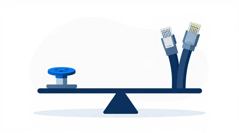
The Total Cost of Ownership (TCO) for 800G OSFP DR8 is significantly influenced by its architectural simplicity, which reduces individual module CAPEX and operational power draw, though it requires a more robust parallel fiber infrastructure compared to WDM-based alternatives like FR8 or LR8. For hyperscale data centers, the DR8 form factor often represents the most cost-effective path to 800G because the savings in silicon photonics and lower power-per-bit offset the higher initial investment in MPO-style cabling.
CAPEX: Module Complexity vs. Cabling Volume
When analyzing Capital Expenditure, the primary trade-off exists between the transceiver hardware and the physical layer media. DR8 modules use eight parallel channels, avoiding the expensive optical multiplexers and de-multiplexers required for wavelength division multiplexing (WDM) found in FR8 modules. However, DR8 requires 16 fibers (8 transmit, 8 receive) per link, whereas FR8 operates over a single duplex fiber pair.
| Cost Component | 800G OSFP DR8 (Parallel) | 800G OSFP FR8 (WDM) |
|---|---|---|
| Relative Module Price | Lower (Simpler Optics) | Higher (Complex MUX/DEMUX) |
| Fiber Infrastructure | High (MPO-16/Parallel) | Low (Standard Duplex LC) |
| Connector Cost | Higher (Precision MTP/MPO) | Lower (Standard LC) |
| Reach Capability | Up to 500m | Up to 2km |
OPEX: Power Efficiency and Cooling ROI
Operating Expenditure is where the 800G OSFP DR8 excels, particularly in large-scale deployments. By utilizing a simpler internal design, DR8 modules typically consume 2-3 Watts less than their FR8 counterparts. Over a standard 3-to-5-year hardware lifecycle in a facility with tens of thousands of ports, this reduction in electricity and the corresponding decrease in cooling requirements results in a massive reduction in utility costs. Furthermore, the OSFP form factor's integrated heatsink improves thermal management, reducing the failure rate and maintenance overhead associated with laser degradation.
- Is the 800G DR8 always cheaper in the long run?
Generally yes for short-reach applications (under 500m) where the volume of transceivers is high. The lower unit cost and power savings usually break even against the higher cabling costs within 18-24 months. - How does maintenance impact the TCO comparison?
Parallel fiber (DR8) requires more rigorous cleaning protocols for MPO connectors to avoid signal loss across multiple fibers. However, the lack of complex WDM components in DR8 modules typically leads to a higher Mean Time Between Failures (MTBF). - Does the choice of form factor affect the upgrade path?
Yes. Choosing OSFP DR8 provides a platform that is better suited for future 1.6T transitions due to its superior thermal envelope, potentially extending the lifespan of the switch chassis and reducing future 'rip-and-replace' costs.
Network Architecture Compatibility and Interoperability

The 800G OSFP DR8 module provides the highest level of architectural flexibility in the current market because its 8-lane parallel design allows for direct 1-to-8 breakouts to 100G or 1-to-2 breakouts to 400G, facilitating a phased upgrade path for leaf-spine fabrics. Unlike WDM-based alternatives that utilize complex wavelength multiplexing, the DR8’s reliance on parallel single-mode fiber (PSM8) ensures that signal integrity is maintained across heterogeneous hardware environments, making it the most interoperable solution for high-density data centers.
Leaf-Spine Integration and Breakout Versatility
Modern data center fabrics rely on high radix switches where port density is a primary metric of success. The 800G OSFP DR8 excels in this environment by utilizing an MPO-16 or dual MPO-12 connector interface. This physical layer configuration allows network architects to utilize 'breakout' mode, where a single 800G port can serve multiple 100G or 400G endpoints. This capability is critical for connecting new 800G spine switches to established 400G leaf nodes without requiring expensive optical conversion hardware.
| Feature | 800G OSFP DR8 | 800G 2xFR4 | 800G LR8 |
|---|---|---|---|
| Optical Lane Mapping | 8 x 100G (Parallel) | 2 x 4 x 100G (WDM) | 1 x 8 x 100G (WDM) |
| Breakout Support | Native 100G/400G | Limited 400G Only | None / Extremely Complex |
| Connector Type | MPO-16 / MPO-12 | Dual LC / CS | Single LC |
| Interoperability | High (Backward & Forward) | Moderate (WDM specific) | Low (Point-to-Point) |
Ensuring Backward Compatibility with 400G DR4
A significant advantage of the DR8 architecture is its synchronization with the IEEE 802.3bs and 802.3ck standards, which define the signaling for 400G and 800G respectively. Because the 800G DR8 uses the same 100G-PAM4 per-lane modulation as the 400G DR4, it can communicate directly with 400G modules using a simple MPO-to-2xMPO breakout cable. This 'pay-as-you-grow' model allows operators to upgrade spine capacity while sweating existing 400G assets in the leaf or server tier.
- Can 800G OSFP DR8 connect directly to legacy 400G switches?
Yes, by using a breakout cable that splits the MPO-16 signal into two MPO-12 or MPO-8 connectors, the DR8 can link directly to two 400G DR4 modules. - Does the DR8 require a specific fiber infrastructure?
It requires Single-Mode Fiber (SMF). While it uses more fiber strands than WDM alternatives, it avoids the cost and complexity of optical mux/demux components. - Is there any latency penalty when interoperating with 400G?
No, because both standards use compatible 100G-PAM4 signaling, there is no need for heavy forward error correction (FEC) transcoding that might introduce significant latency.
Strategic Recommendation: Choosing Your Path to 800G
The decision between 800G OSFP DR8 and its alternatives—primarily FR8 and LR8—is dictated by the trade-off between transceiver complexity and fiber plant density. For the majority of internal data center fabrics, the OSFP DR8 is the superior choice due to its lower power consumption and native support for 100G breakout configurations. However, as the distance between network nodes increases or fiber availability becomes a constraint, the multiplexed approach of FR8 and LR8 becomes economically and technically necessary.
Decision Matrix: Deployment Scenarios and Module Selection
| Use Case | Recommended Module | Max Reach | Primary Advantage |
|---|---|---|---|
| AI/ML Compute Clusters | OSFP DR8 | 500m | Lowest latency and breakout flexibility |
| Spine-to-Leaf Fabric | OSFP DR8 / DR8+ | 500m - 2km | Optimal power efficiency per Gigabit |
| Campus Interconnect | OSFP FR8 | 2km | Reduced fiber count via CWDM8 |
| Data Center Interconnect (DCI) | OSFP LR8 | 10km | Long-reach without external amplification |
The Case for DR8: Hyperscale and AI Dominance
For CTOs overseeing AI-heavy workloads or hyperscale leaf-spine architectures, the OSFP DR8 is the industry standard for a reason. By utilizing 8 parallel channels of 100G PAM4, the DR8 module minimizes the internal DSP complexity required for wavelength multiplexing. This results in significantly lower thermal output and a lower cost-per-bit. Furthermore, the DR8’s ability to interface directly with 400G DR4 modules provides a seamless migration path for brownfield environments.
When to Pivot to FR8 and LR8
The shift to FR8 or LR8 should be triggered specifically by fiber scarcity or physical distance. In scenarios where installing new conduits is cost-prohibitive, the 8-wavelength multiplexing of the FR8 allows for 800G throughput over a single pair of LC-terminated fibers. While the transceiver CAPEX is higher compared to DR8, the OPEX savings in fiber management and the avoidance of massive MPO cable deployments often justify the investment for campus-scale distances.
Strategic Implementation FAQ
- Does DR8 support 8x100G breakout?
Yes, DR8 is specifically designed for high-density breakout, allowing a single 800G port to connect to eight 100G edge devices or two 400G leaf switches, maximizing port utilization. - How does power consumption differ between DR8 and FR8?
OSFP DR8 modules typically consume 14-16W, whereas FR8 modules can reach 18W+ due to the additional complexity of the laser coolers and optical mux/demux components. - Which module is most future-proof for 1.6T transitions?
DR8 architectures align more closely with the next-generation 200G-per-lane signaling standards, making the transition to 1.6T DR8-200 more evolutionarily consistent for current parallel fiber users.
Navigating the 800G transition requires balancing immediate performance needs with long-term infrastructure scalability. The OSFP DR8 offers a compelling mix of thermal headroom and cost-efficiency for modern high-density environments. Ready to upgrade your fabric? Contact our engineering team for a customized 800G TCO audit today.