In the high-stakes world of 400G and 800G networking, the smallest particle of dust can become a massive bottleneck. As data centers push the limits of physics, the hygiene of MPO and LC connectors has transitioned from a routine task to a critical performance lever. This article provides a data-driven comparison of professional cleaning protocols versus common industry alternatives, focusing on the metrics that matter most to CTOs: latency, power efficiency, and long-term financial viability.
The Critical Role of Fiber Hygiene in High-Bandwidth Ecosystems
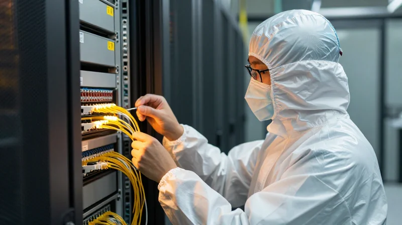
In high-bandwidth ecosystems like hyperscale data centers and 5G backhaul, fiber hygiene is the single most important factor determining the reliability of the physical layer. As data rates climb from 10G to 400G and beyond, the tolerance for signal loss narrows significantly. A microscopic particle on an LC or MPO connector does not merely obstruct light; it changes the refractive index, causing reflections that can damage sensitive transceiver optics and trigger intermittent link failures that are notoriously difficult to troubleshoot.
The Physics of Contamination in High-Speed Links
The core of a single-mode fiber is approximately 9 microns in diameter, which is significantly smaller than a human hair or a common dust particle. When a connector is mated, any debris present is crushed between the glass end-faces. In high-power applications, this debris can lead to 'pitting'—permanent physical damage where the contaminant burns into the glass, rendering the cable or the expensive transceiver port permanently defective.
Comparison of Vulnerabilities: LC vs. MPO
| Parameter | LC Connector (Single-fiber) | MPO Connector (Multi-fiber) |
|---|---|---|
| Contamination Risk | Isolated to one link | Spreads across 12-32 fibers |
| Mating Pressure | Lower, centered | Higher, susceptible to ferrule tilt |
| Failure Mode | Signal attenuation | Link-wide synchronization errors |
Critical Performance FAQ
- How does dirt affect 400G networks specifically?
High-speed optics use complex modulation like PAM4, which is far more sensitive to the signal-to-noise ratio (SNR) degradation caused by dirty connectors. - Is 'dry cleaning' enough for MPO?
While dry cleaning is a start, 'wet-to-dry' cleaning is often required to remove stubborn ionic soils that cause permanent pitting under high-power laser exposure. - What is the 'Inspect Before You Connect' standard?
This industry-standard (IEC 61300-3-35) mandates that every connector be inspected with a microscope and cleaned if necessary before every single mating cycle.
The Physics of Contamination: How Micro-Dust Disrupts Light Paths

Micro-contamination on a fiber optic end-face acts as a physical barrier that disrupts the precision-engineered light path between two mated connectors. Because a single-mode fiber core is only 9 microns in diameter—smaller than a human red blood cell—even a microscopic speck of dust or a smudge of skin oil can cause significant signal attenuation or catastrophic hardware damage due to high-power laser absorption.
The Mechanics of Insertion Loss (IL)
Insertion loss occurs when light is absorbed, scattered, or blocked by a foreign object at the connection point. When a particle is trapped between two ferrules, it prevents the cores from making physical contact. This creates an air gap, which has a different refractive index than the glass cores, causing the light to diverge and miss the receiving fiber. In high-density MPO connectors, a single large particle can tilt the entire MT ferrule, causing alignment issues across all 12 or 24 fibers simultaneously.
Back-Reflection and Optical Return Loss (ORL)
Optical Return Loss refers to the amount of light reflected back toward the source. Contaminants like skin oils or cleaning fluid residue change the refractive index at the interface. Instead of passing through to the next fiber, the light energy is reflected back into the transmitting laser. This back-reflection increases the Bit Error Rate (BER) and, in high-power systems, can generate enough heat at the contamination site to permanently 'pit' or burn the glass end-face.
| Contaminant Type | Primary Optical Effect | Physical Risk |
|---|---|---|
| Dry Dust (Silica/Lint) | Scattering & Insertion Loss | Scratches the ferrule during mating |
| Skin Oils | Refractive Index Shift | Attracts more dust; causes 'smearing' |
| Cleaning Residue | Back-Reflection (ORL) | Forms a film that hardens over time |
| Moisture/Condensation | Diffraction | Can lead to signal instability |
- Why is dust more dangerous in MPO connectors than LC?
MPO connectors use a larger surface area and pins for alignment. A single particle can prevent the entire array from seating properly, affecting multiple channels at once, whereas an LC connector only affects a single link. - Can I just blow on the connector to clean it?
No. Human breath contains moisture and oils that create a film on the end-face. Furthermore, compressed air cans often expel propellants that leave chemical residues, worsening the optical Return Loss. - What is 'ghosting' in the context of contamination?
Ghosting refers to secondary signals created by back-reflection that interfere with the primary data stream, leading to packet loss and decreased network throughput.
Latency Analysis: Linking Dirty Connectors to Packet Retransmission
The relationship between fiber connector cleanliness and network performance is a transition from optical physics to temporal integrity. Contamination on MPO or LC end-faces introduces physical impediments that scatter light, leading to a degraded signal-to-noise ratio and a surge in the Bit Error Rate (BER). When the BER exceeds the threshold manageable by Forward Error Correction (FEC), the transport layer must initiate packet retransmissions. For latency-sensitive applications like High-Frequency Trading (HFT) or distributed AI model training, these millisecond-level delays aggregate into significant performance bottlenecks, effectively nullifying the throughput advantages of high-bandwidth hardware.
The Cascade Effect: From Photons to Retransmissions
In a pristine fiber environment, data packets travel with minimal interruption. However, microscopic debris—ranging from skin oils to dust—on a connector causes insertion loss and back-reflection (return loss). This physical layer degradation forces the receiver's photodetector to struggle with interpreting logic levels. Modern 400G and 800G networks rely on PAM4 modulation and Forward Error Correction (FEC) to repair minor errors. However, when contamination-induced noise is too severe for FEC to resolve, the packet is discarded. The resulting Request for Retransmission (ARQ) introduces a Round Trip Time (RTT) penalty that is orders of magnitude greater than the original propagation delay.
| Performance Metric | Clean Connector (Optimal) | Dirty Connector (Marginal) | Contaminated Connector (Critical) |
|---|---|---|---|
| Insertion Loss | < 0.25 dB | 0.5 - 1.5 dB | > 2.5 dB |
| Bit Error Rate (BER) | 10^-12 | 10^-9 | 10^-5 |
| FEC Utilization | Minimal Overhead | Frequent Correction | FEC Failure / Frame Loss |
| Latency Profile | Stable (Nanoseconds) | Jitter (Microseconds) | Retransmission Spikes (Milliseconds) |
Case Study: High-Frequency Trading and AI Fabrics
In the world of High-Frequency Trading, a delay of 100 microseconds can result in substantial lost opportunities as market data arrives late. Similarly, AI workloads involving Large Language Model (LLM) training rely on massive, synchronized data exchanges across InfiniBand or Ethernet fabrics. A single dirty MPO connector in a GPU cluster can create a 'straggler' effect; the entire parallel processing job pauses to wait for a retransmitted packet from one contaminated link, drastically reducing the effective TeraFLOPS and increasing the total cost of compute time.
- Why does a 0.5dB loss matter in high-speed links?
In 400G+ systems using PAM4, signal levels are compressed. A 0.5dB loss significantly reduces the 'eye opening' of the signal, making it difficult for receivers to distinguish between levels, which drives up the BER. - Can software-defined networking (SDN) mitigate dirty connector latency?
No. While SDN can reroute traffic, it cannot compensate for the physical signal loss of a specific link. Rerouting itself often introduces more latency than a clean, direct physical connection. - Is jitter a direct result of contamination?
Yes. Inconsistent signal quality caused by shifting debris or thermal expansion at a dirty interface causes the time-of-arrival for packets to vary, disrupting synchronization in real-time protocols.
Power Consumption: The Hidden Energy Cost of Signal Compensation
The Direct Link Between Signal Loss and Power Draw
Maintaining optimal physical layer cleanliness is a direct prerequisite for energy efficiency in high-density MPO and LC environments. When dust or oils obstruct the light path, optical transceivers automatically increase laser bias currents and digital signal processing (DSP) intensity to overcome the resulting signal-to-noise ratio (SNR) degradation. This 'powering through' the contamination leads to a measurable increase in watt-per-port consumption, which aggregates into substantial operational expenses across large-scale deployments.
The Hidden Wattage: Transceiver DSP and FEC Stress
As the Bit Error Rate (BER) rises due to physical obstructions on the connector end-face, the transceiver’s Forward Error Correction (FEC) engine must work harder to reconstruct lost data packets. This increased computational load at the silicon level translates to higher thermal output and power draw. In large-scale data centers with tens of thousands of links, the cumulative energy required to compensate for dirty fiber connections can represent 2-5% of the total network power budget, a cost that is entirely avoidable through proactive cleaning rather than hardware-based signal boosting.
| Metric | Clean Connector (MPO/LC) | Contaminated Connector (Compensated) |
|---|---|---|
| Laser Bias Current | Standard (Optimal) | Elevated (10-15% increase) |
| DSP Computational Load | Low/Efficient | High (Intensive FEC) |
| Heat Dissipation Needs | Nominal | Increased (Higher Fan Speed/Cooling) |
| Estimated Port Power Draw | 3.5W - 12W Baseline | +0.5W to +1.5W per link |
Sustainability and ESG Goals
Maintaining pristine fiber end-faces is not merely a performance requirement; it is a critical component of Environmental, Social, and Governance (ESG) strategies. By reducing the electrical overhead of optical links, data center operators can significantly lower their Power Usage Effectiveness (PUE) and total carbon footprint. Furthermore, by preventing transceivers from running at maximum power and temperature, cleaning extends the operational lifespan of the hardware, reducing e-waste and long-term capital expenditure.
- Does dirty fiber shorten transceiver life?
Yes. High laser bias currents and increased heat from constant signal compensation accelerate the degradation of optical components like VCSELs and EMLs, leading to premature failure. - Can cleaning really impact PUE?
In hyperscale environments, saving even 0.5W per port across 100,000 links translates to 50kW of continuous power savings, excluding the additional energy saved on facility cooling. - Are 'Alternative' non-cleaning methods effective for power?
Typically no; software-based signal boosting or 'burn-in' techniques only mask the physical problem while permanently increasing the electrical draw and thermal output of the network.
MPO vs. LC Cleaning Challenges: Multi-Fiber vs. Single-Fiber Dynamics
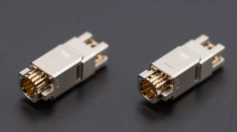
Cleaning MPO connectors is significantly more complex than cleaning LC connectors because the multi-fiber array surface area allows for debris migration and requires higher precision tools to ensure all channels are clear simultaneously. In an LC environment, the technician deals with a single 1.25mm point of failure. In MPO environments, a single microscopic particle on the ferrule can be crushed during mating, distributing shards across 12 or 24 fibers and causing a total link failure or high Bit Error Rates (BER) across the entire parallel ribbon.
Physical Architecture and Debris Traps
The primary difference lies in the ferrule geometry. LC connectors use a cylindrical ceramic ferrule that is easy to rotate and wipe. MPO connectors utilize a large, flat rectangular ferrule that is prone to attracting more static-charged dust. Furthermore, MPO connectors often feature stainless steel alignment pins (male) or holes (female). These pins act as obstacles for cleaning cloths and pens, often trapping dust at the base of the pin which then migrates to the fiber cores during the connection process.
| Feature | LC (Single-Fiber) | MPO (Multi-Fiber) |
|---|---|---|
| Ferrule Shape | 1.25mm Circular | Large Rectangular |
| Fiber Count | 1 | 12 to 32 |
| Alignment | Alignment Sleeve | Pins and Holes |
| Risk Factor | Single point of failure | Multi-channel cross-contamination |
| Cleaning Tool | 1.25mm Clicker/Pen | MPO-specific Cassette/Pen |
The Migration Effect: Why MPO Cleaning is High-Stakes
In MPO connectors, the 'migration effect' is a critical concern. When a connector is mated, the high spring force required to ensure physical contact across all fibers can pulverize a piece of dust. Because the fibers are spaced only 250 microns apart, the resulting debris cloud can coat every fiber in the row. This makes the 'Inspect-Clean-Inspect' workflow mandatory for MPO, whereas technicians often take shortcuts with LC—a practice that is dangerous but less likely to cause a multi-port outage.
Common Questions Regarding MPO and LC Maintenance
- Can I use an LC cleaning pen on an MPO connector?
No. LC pens are designed for 1.25mm circular ferrules and cannot cover the wide rectangular surface area or navigate the alignment pins of an MPO connector. - Is wet cleaning better for MPO?
A 'wet-to-dry' method is often recommended for MPO to dissipate static and remove heavy oils that accumulate on the larger surface area, followed by a dry wipe to ensure no residue remains. - Why does MPO fail inspection more often?
The presence of alignment pins and the sheer number of fibers increase the statistical likelihood that at least one zone will be contaminated, requiring a recleaning of the entire array.
Comparing the Alternatives: Manual Swabs, Click-Cleaners, and Automated Systems

Comparing the Alternatives: Manual Swabs, Click-Cleaners, and Automated Systems
The choice between manual swabs, click-cleaners, and automated systems is a trade-off between operational speed, technical precision, and long-term reliability. While manual swabs are essential for 'deep cleaning' stubborn oils, automated systems are the only method that guarantees the repeatable results required for high-density MPO deployments and IEC 61300-3-35 compliance in mission-critical environments.
The Performance Hierarchy: Consistency and Contamination Removal
Manual swabs remain the baseline for versatility, allowing technicians to apply specific solvents and physical pressure to dislodge embedded debris. However, this method is highly subjective; variations in technician pressure and 'wet-to-dry' technique often result in cross-contamination or residue streaks. One-click cleaners (mechanical push-style) mitigate this by using a pre-tensioned cleaning ribbon that provides a consistent stroke. While excellent for loose dust and standard maintenance, click-cleaners often struggle with heavy fluid contamination on LC or MPO end-faces because they lack the localized agitation provided by a manual or automated scrub.
| Feature | Manual Swabs | Click-Cleaners | Automated Systems |
|---|---|---|---|
| Cleaning Consistency | Low (Operator Dependent) | Medium (Fixed Tension) | High (Robotic Precision) |
| MPO Efficiency | Poor (Hard to align) | Good (Rapid application) | Excellent (Full-face coverage) |
| Risk of Damage | High (Scratches from debris) | Low (Controlled force) | Minimal (Non-contact options) |
| IEC 61300-3-35 Pass Rate | ~65-75% (First Pass) | ~85-90% (First Pass) | 98%+ (First Pass) |
| Cost Per Clean | ~$0.08 - $0.12 | ~$0.25 - $0.40 | ~$0.60 - $1.20 |
Strategic Use Cases for Each Method
Automated cleaning systems represent the gold standard for hyperscale data centers and high-volume manufacturing. By integrating inspection and cleaning into a single automated workflow, these systems eliminate the 'clean-inspect-reclean' cycle that accounts for 50% of installation labor costs. For field technicians working on standard LC patch panels, click-cleaners offer the best balance of speed and effectiveness. Manual swabs should be reserved for troubleshooting failed links where automated or mechanical tools have already failed to clear the end-face.
- Can click-cleaners handle heavy oil or grease?
Generally no; dry click-cleaners are designed for dust and light oils. For heavy grease, a 'wet-dry' combination using a manual swab or an automated solvent-based system is required. - Why are automated systems better for MPO connectors?
MPO connectors have a large surface area and alignment pins that catch dirt. Automated systems use precise paths to ensure the entire array is cleaned without pushing debris into the fiber holes. - Is the higher cost of automated cleaning justified?
In AI and high-frequency trading environments, the cost is justified by the reduction in Bit Error Rates (BER) and the elimination of human error, which can cause multi-million dollar outages.
Total Cost of Ownership (TCO) Breakdown: Proactive vs. Reactive Maintenance
Total Cost of Ownership: Why Proactive Cleaning is an Investment, Not an Expense
The financial reality of fiber optic networks is that the cost of high-quality cleaning supplies is an insurance premium against the catastrophic expenses of network downtime and hardware replacement. Proactive maintenance—cleaning and inspecting every LC or MPO connector before mating—ensures that the physical layer remains within the strict loss budgets required for 400G and 800G speeds. A reactive approach, which only addresses contamination after a link failure is detected, leads to a significantly higher TCO due to emergency labor rates, service level agreement (SLA) penalties, and the irreversible degradation of expensive optical transceivers caused by 'mated-in' debris.
| Financial Metric | Proactive (MPO/LC Cleaning) | Reactive (Break-Fix Model) |
|---|---|---|
| Average Cost per Connection | $0.15 - $0.65 | $150 - $1,200 (Labor/Travel) |
| Transceiver Replacement Rate | Low (<1% annually) | High (Contamination damage) |
| Network Downtime Risk | Minimal / Scheduled | High / Unscheduled Outages |
| Link Performance | Optimal (Low DB Loss) | Sub-optimal (High Bit Error Rate) |
| Operational Efficiency | Predictable OpEx | Volatile / Emergency CapEx |
The Hidden Costs of 'Saving' on Cleaning Tools
Organizations often attempt to lower costs by purchasing subpar cleaning alternatives or bypassing inspection entirely. However, this creates a 'hidden' debt. When a dirty MPO connector is mated, the pressure can embed dust particles into the glass, creating permanent pits and scratches. This not only ruins the cable but can also damage the internal optics of the switch. Replacing a high-density line card or a proprietary MPO trunk cable costs thousands of dollars—a figure that dwarfs the $60 price tag of a professional-grade click-cleaner.
- How does proactive cleaning impact SLA compliance?
Proactive cleaning eliminates the most common cause of intermittent signal loss, ensuring that network uptime remains within the 'five nines' (99.999%) required by modern SLAs, thereby avoiding heavy financial penalties. - Is there a measurable ROI on automated inspection tools?
Yes. Automated inspection tools provide a digital audit trail and 'Pass/Fail' certification based on IEC standards, which reduces troubleshooting time by up to 50% during initial deployment and troubleshooting. - Does cleaning actually extend the life of the hardware?
Absolutely. By preventing back-reflection (ORL) and heat buildup at the connection point, clean fiber interfaces allow transceivers to operate at lower power levels and cooler temperatures, extending their mean time between failures (MTBF).
Operational Efficiency: Standardizing Cleaning Protocols for Enterprise Scale
Operational Efficiency: Standardizing Cleaning Protocols for Enterprise Scale
To achieve operational efficiency at an enterprise scale, organizations must transition from reactive cleaning to a standardized, protocol-driven architecture. Standardizing Fiber Connector Cleaning (MPO/LC) involves the institutionalization of the 'Inspect-Before-You-Connect' methodology, ensuring that every technician—regardless of experience level—adheres to a uniform set of validated steps. This consistency is the only way to mitigate the cumulative risk of signal degradation and hardware damage across thousands of fiber terminations in high-density data centers.
The 'Inspect-Clean-Inspect' (ICI) Workflow
The ICI workflow is the cornerstone of professional fiber management. Enterprises must mandate that no connector is mated without visual verification. If a connector fails the initial inspection based on IEC 61300-3-35 criteria, it must be cleaned using a validated tool—such as a precision click-cleaner or an automated solvent-based system—and immediately re-inspected. This loop prevents the transfer of contaminants between the connector and the bulkhead, which is the leading cause of permanent ferrule damage in MPO-heavy environments.
| Protocol Element | Manual/Ad-hoc Approach | Standardized Enterprise Approach |
|---|---|---|
| Inspection Reporting | Often skipped or undocumented | Digital pass/fail reports saved to cloud |
| Tool Selection | Technician preference (Swabs/Pens) | Standardized kits per connector type (MPO/LC) |
| Compliance Monitoring | Visual spot checks | Automated software logs & remote audits |
| Pass/Fail Criteria | Subjective visual check | IEC 61300-3-35 automated analysis |
Training and Data-Driven Compliance
Scaling operations effectively requires an investment in technician training and the use of smart tools that log performance data. Modern fiber inspection probes can automatically sync results to a centralized database via mobile applications. This allows network managers to audit site readiness remotely and identify teams or vendors who may be skipping cleaning steps. By establishing a clear audit trail, enterprises ensure long-term infrastructure integrity and maintain EEAT-compliant management practices that protect the network's lifecycle.
- How does standardization reduce TCO?
By minimizing 'redo' rates and preventing physical hardware damage, standardized protocols reduce the labor costs associated with troubleshooting and the capital expenditure of replacing fouled transceivers. - Should MPO cleaning differ from LC cleaning in the SOP?
Yes. MPO connectors have larger surface areas and alignment pins that require specific tools like multi-fiber click-cleaners, whereas LC connectors require 1.25mm tips. The SOP must specify the exact tool for each interface. - What is the role of automated inspection in scaling?
Automated inspection removes human subjectivity. It ensures that every fiber meets the IEC standard based on objective software algorithms rather than a technician's eyesight, which is critical for 400G/800G deployments.
Future-Proofing: Preparing for 1.6T and Co-Packaged Optics (CPO)

Future-Proofing: Preparing for 1.6T and Co-Packaged Optics (CPO)
The evolution toward 1.6 Terabit (1.6T) networking and Co-Packaged Optics (CPO) fundamentally alters the risk profile of fiber contamination. At these speeds, the optical power budgets are so narrow that the insertion loss and back-reflection caused by a single microscopic dust particle can render a multi-thousand-dollar link inoperable. Unlike previous generations where 'cleaning' was a maintenance suggestion, for 1.6T and CPO, it is a critical manufacturing and deployment prerequisite.
The 1.6T Challenge: Zero-Tolerance Power Budgets
1.6T Ethernet, typically utilizing 200G-per-lane signaling, relies on complex modulation schemes like PAM4. These schemes are extremely sensitive to Signal-to-Noise Ratio (SNR) degradation. Contaminants on an MPO-32 or SN/MDC connector don't just cause simple loss; they create reflections that interfere with the laser's performance. As we move to 1.6T, the acceptable loss per connection point is trending toward less than 0.1 dB, leaving no room for the attenuation caused by skin oils or environmental particulates.
Co-Packaged Optics (CPO): Bringing the Fiber to the Silicon
CPO technology relocates the optical engine from a pluggable transceiver to the same substrate as the switch ASIC. This drastically increases the density of fiber interconnects on the faceplate and inside the chassis. Because CPO modules are often non-serviceable or difficult to access compared to front-panel pluggables, the 'clean-once, clean-right' philosophy becomes paramount. A contaminated internal CPO interface could require the replacement of the entire switch fabric rather than just a modular transceiver.
| Metric | Legacy (100G/400G) | Next-Gen (1.6T/CPO) |
|---|---|---|
| Typical Loss Budget | ~2.0 dB - 3.0 dB | < 1.0 dB (Total Link) |
| Connector Type | LC / MPO-12 | MPO-32 / SN / MDC / ELSFP |
| Sensitivity to Dust | Moderate (Packet Loss) | Extreme (Link Drop/Laser Damage) |
| Cleaning Priority | Maintenance Task | Mission-Critical Protocol |
Strategic Implementation for Next-Gen Optics
- Will 1.6T require new cleaning tools?
Yes, the shift toward Very Small Form Factor (VSFF) connectors like SN and MDC, as well as higher-density MPO-32 interfaces, requires specialized cleaning tips and automated inspection probes designed for tighter spatial tolerances. - Why is 'Dry Cleaning' potentially insufficient for CPO?
With CPO, the thermal environment is more intense. Residual oils can 'bake' onto the fiber end-face. A 'Wet-to-Dry' cleaning process is recommended to ensure all ionic and non-ionic contaminants are removed before high-power lasers are energized. - How does automated inspection impact 1.6T reliability?
Automated inspection removes human error by using AI algorithms to grade end-faces against the IEC 61300-3-35 standard, ensuring that every link in a 1.6T fabric meets the rigorous reflectance specifications required for PAM4 stability.
In summary, future-proofing your infrastructure for 1.6T and CPO is not just about buying the right glass; it is about mastering the environment in which that glass operates. As hardware costs rise and signal tolerances vanish, the humble cleaning pen and inspection scope evolve from simple tools into the guardians of network uptime.
Effective fiber maintenance is no longer optional; it is a strategic necessity for maintaining low-latency, energy-efficient networks. By investing in the right cleaning protocols today, organizations can significantly reduce their TCO and ensure long-term hardware reliability. Ready to optimize your fiber infrastructure? Contact our technical team for a custom maintenance audit.