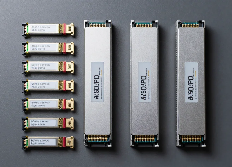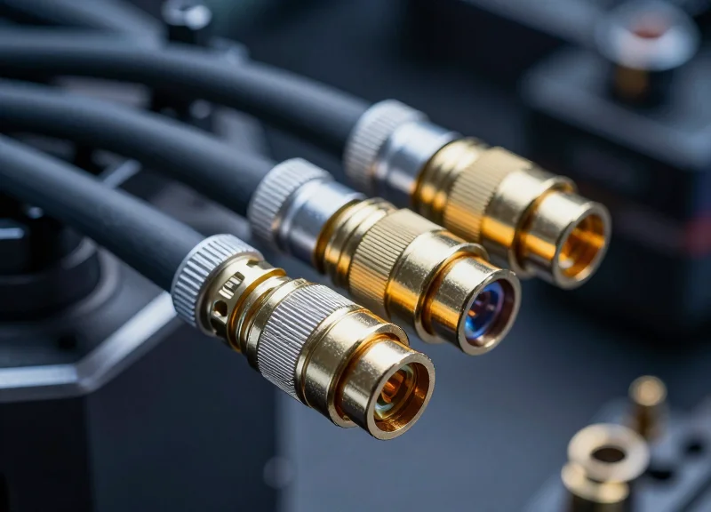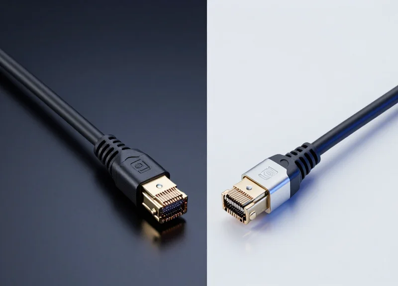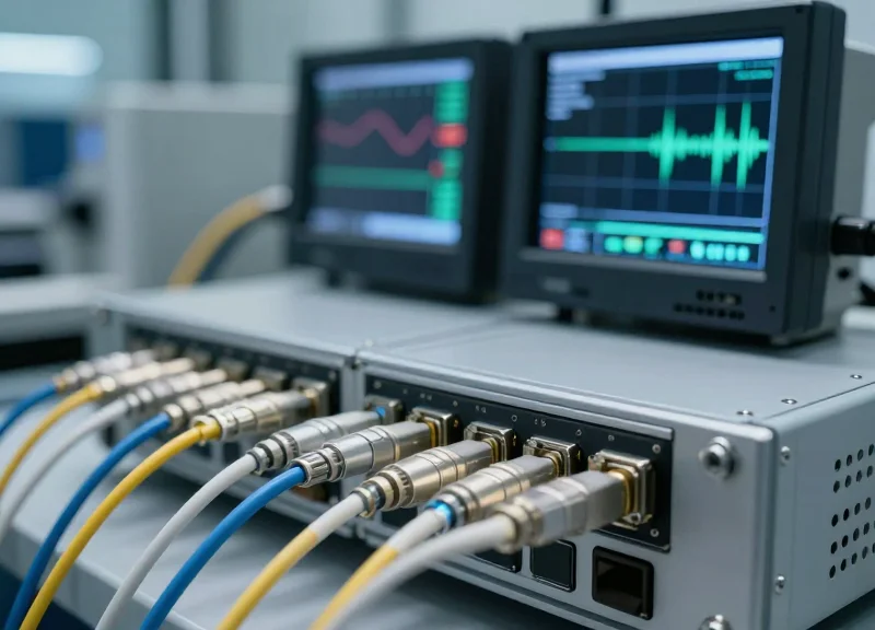
As hyperscale data centers and cloud providers push the boundaries of bandwidth, the shift from 100G to 400G has highlighted 200G FR4 as a critical, cost-effective solution for mid-range connectivity. This guide explores the technical foundation and strategic advantages of 200G FR4 in modern infrastructure.
Defining 200G FR4: The QSFP56 Standard
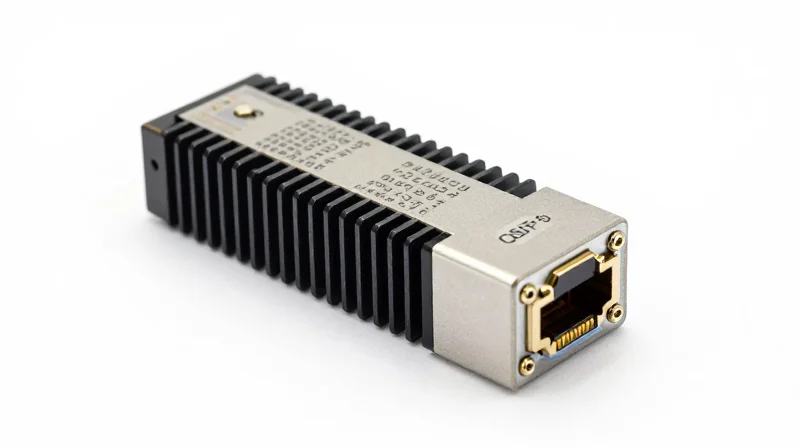
The 200G FR4 solution is a specialized optical transceiver standard designed to meet the increasing bandwidth demands of modern data centers and enterprise networks. It functions by aggregating four 50Gbps lanes into a single 200G link using Coarse Wavelength Division Multiplexing (CWDM). Specifically engineered for single-mode fiber (SMF), the 'FR' designation indicates a reach of up to 2 kilometers, positioning it as the ideal middle-ground solution between short-reach multi-mode optics and long-haul single-mode alternatives.
The QSFP56 Form Factor and PAM4 Modulation
At the heart of the 200G FR4 specification is the QSFP56 (Quad Small Form-factor Pluggable 56) module. While it maintains the same physical dimensions as the legacy QSFP28, the QSFP56 represents a significant leap in signal integrity and data density. The transition from 100G to 200G was primarily enabled by the move from NRZ (Non-Return-to-Zero) to PAM4 (4-level Pulse Amplitude Modulation) signaling. By doubling the number of bits per symbol, PAM4 allows the transceiver to handle 50Gbps per lane, effectively doubling the capacity of the standard four-lane QSFP architecture.
IEEE 802.3bs and 802.3cd Standardization
The technical framework for 200G FR4 is governed by the IEEE 802.3bs and IEEE 802.3cd standards. IEEE 802.3bs laid the groundwork for 200GbE and 400GbE operations, defining the core physical coding sublayer (PCS) and forward error correction (FEC) requirements. IEEE 802.3cd further refined these specifications for 50G, 100G, and 200G operation, ensuring interoperability between different vendors. This standardization ensures that 200G FR4 modules can reliably operate in a multi-vendor ecosystem, providing a stable path for network scaling.
| Feature | 200G FR4 Specification |
|---|---|
| Form Factor | QSFP56 |
| Optical Interface | Duplex LC |
| Modulation | PAM4 |
| Wavelengths | 1271, 1291, 1311, 1331 nm (CWDM4) |
| Maximum Reach | 2 km |
| Power Consumption | Typically <5.5W |
Frequently Asked Questions about 200G FR4
- Why is the 2km distance significant?
The 2km reach is optimized for large-scale data center leaf-spine architectures where 500m (DR4) is insufficient, but 10km (LR4) is unnecessarily expensive. - Does 200G FR4 require FEC?
Yes, because of the tighter signal-to-noise ratios inherent in PAM4 modulation, 200G FR4 relies on KP4 Forward Error Correction (FEC) to ensure error-free data transmission. - Is QSFP56 backward compatible with QSFP28?
While they share the same physical shape, QSFP56 ports are designed for PAM4. A QSFP56 port can often support a QSFP28 module (NRZ), but a QSFP56 module cannot operate in a legacy QSFP28 port.
The Core Technology: PAM4 Modulation Explained

The Core Technology: PAM4 Modulation Explained
PAM4 (Four-Level Pulse Amplitude Modulation) is the critical signaling technology that allows 200G FR4 transceivers to transmit data at 200Gbps across just four optical lanes. Unlike traditional Non-Return-to-Zero (NRZ) signaling, which uses two voltage levels to represent a 0 or 1, PAM4 utilizes four distinct signal levels (0, 1, 2, and 3). This enables the transmission of two bits of information per symbol period, effectively doubling the data density without requiring a doubling of the optical bandwidth.
Comparing NRZ and PAM4 Signaling
The transition from 100G (typically NRZ-based) to 200G necessitated a shift in modulation because increasing the clock speed of NRZ to reach 50G per lane would cause severe signal integrity issues and excessive power consumption. PAM4 solves this by maintaining a manageable baud rate while increasing the bit rate.
| Feature | NRZ (2-Level) | PAM4 (4-Level) |
|---|---|---|
| Bits per Symbol | 1 Bit | 2 Bits |
| Signal Levels | 2 (High/Low) | 4 (00, 01, 10, 11) |
| Bandwidth Efficiency | Baseline | 2x Higher than NRZ |
| Signal-to-Noise Ratio (SNR) | High | Lower (approx. -9.5 dB penalty) |
| Error Correction | Optional/Simple | Mandatory (KP4 FEC) |
Achieving 50G Throughput per Lane
In a 200G FR4 QSFP56 module, the electrical interface and the optical interface both utilize four lanes. To reach the 200Gbps aggregate capacity, each lane must operate at 50Gbps. Using PAM4, the baud rate for each lane is approximately 26.5625 Gbaud. Because each baud (symbol) carries two bits, the resulting data rate is 53.125 Gbps per lane (inclusive of overhead for Forward Error Correction). When four of these lanes are multiplexed using Coarse Wavelength Division Multiplexing (CWDM), the total capacity hits the 212.5 Gbps gross rate required for a 200Gbps Ethernet payload.
- Why is FEC necessary for PAM4?
Because PAM4 has four signal levels packed into the same voltage swing as NRZ, the 'eye' openings are much smaller, making the signal more susceptible to noise. Forward Error Correction (FEC), specifically KP4 FEC, is used to detect and correct bit errors at the receiving end, ensuring link stability. - Does PAM4 increase latency?
Slightly. The digital signal processing (DSP) required for PAM4 modulation and the computational overhead of FEC add a small amount of latency (typically in the nanosecond range) compared to simple NRZ signaling. - Is PAM4 backward compatible with NRZ?
While the physical signals are different, many modern DSPs in 200G transceivers are capable of 'gearboxing' or translating between NRZ electrical signals from older switches and PAM4 optical signals, though the 200G FR4 standard specifically defines a PAM4-to-PAM4 link.
CWDM4 Wavelength Architecture

CWDM4 Wavelength Architecture
The CWDM4 architecture in 200G FR4 solutions leverages Coarse Wavelength Division Multiplexing to combine four distinct optical signals—each carrying 50Gbps via PAM4 modulation—onto a single pair of single-mode fibers (SMF). By utilizing a 20nm channel spacing across the 1271nm to 1331nm range, this architecture achieves an aggregate 200G throughput while significantly reducing the physical fiber count compared to parallel optics solutions.
The 20nm Optical Grid Specification
| Channel Designation | Center Wavelength (nm) | Wavelength Range (nm) |
|---|---|---|
| L0 | 1271 | 1264.5 to 1277.5 |
| L1 | 1291 | 1284.5 to 1297.5 |
| L2 | 1311 | 1304.5 to 1317.5 |
| L3 | 1331 | 1324.5 to 1337.5 |
The selection of these specific wavelengths is strategically situated within the O-band (Original Band). This region is critical for 200G transmission because it corresponds to the zero-dispersion window of standard G.652 single-mode fiber. By operating near the zero-dispersion point, 200G FR4 modules can maintain signal integrity over 2km distances without requiring the complex chromatic dispersion compensation circuitry necessary for C-band or long-haul transmissions.
Design Advantages of the CWDM4 Grid
- Why is 20nm spacing used instead of DWDM?
The 20nm spacing allows for the use of uncooled lasers. Unlike DWDM, which requires tight thermal management via Thermo-Electric Coolers (TEC) to maintain sub-nanometer accuracy, CWDM can accommodate wavelength shifts caused by temperature fluctuations, reducing overall power consumption and transceiver cost. - What is the role of the internal MUX/DEMUX?
Within the QSFP56 module, an optical multiplexer (MUX) combines the four 1271-1331nm lanes into a single output fiber. On the receiving end, a demultiplexer (DEMUX) splits the incoming composite signal back into four separate wavelengths to be processed by the PIN photodiode array. - How does it optimize data center cabling?
By multiplexing four channels onto one fiber pair, 200G FR4 reduces the required fiber infrastructure by 75% compared to SR4 or PSM4 solutions, which require eight fibers for a single link. This leads to higher density and lower cable management complexity in the spine-leaf architecture.
In summary, the CWDM4 wavelength architecture is the cornerstone of the FR4 specification. It provides a balanced approach to high-speed networking by utilizing the low-dispersion properties of the O-band and the cost-effective nature of uncooled laser technology, facilitating efficient 200G connectivity over established single-mode fiber plants.
Optical Performance and Link Budget
Decoding the 200G FR4 Link Budget
The 200G FR4 solution is specifically engineered to support 2km transmission distances over duplex single-mode fiber (SMF), filling the critical gap between 500m (DR4) and 10km (LR4) applications. By utilizing the O-band CWDM grid, FR4 minimizes the impact of chromatic dispersion while maintaining a power budget that accommodates the inherent signal-to-noise ratio (SNR) challenges of four-level pulse amplitude modulation (PAM4).
| Parameter | Value (Per Lane) | Units |
|---|---|---|
| Max Channel Insertion Loss | 4.0 | dB |
| Transmitter Launch Power (Average) | -3.8 to +4.5 | dBm |
| Max TDECQ (Transmitter Eye Closure) | 3.4 | dB |
| Receiver Sensitivity (OMA outer) at 2.4e-4 BER | -8.2 | dBm |
| Damage Threshold | +5.5 | dBm |
Managing Insertion Loss and Connector Density
The 4.0 dB link budget for 200G FR4 is notably tighter than legacy 100G NRZ-based standards. This budget must account for both fiber attenuation—typically 0.4 to 0.5 dB per kilometer in the 1310nm range—and the cumulative loss from patch panels, connectors, and splices. In modern hyperscale data centers, where multiple cross-connects are common, the available margin for optical connections is roughly 3.0 dB after fiber loss is subtracted, necessitating high-quality, low-loss LC or MPO terminations to prevent link instability.
TDECQ: The Critical Metric for PAM4 Integrity
Traditional eye-mask testing is insufficient for 200G FR4 due to the vertical compression of the three signal eyes in PAM4. Instead, the industry uses TDECQ (Transmitter and Dispersion Eye Closure Quaternary). This metric quantifies the extra noise power penalty required for a real-world transmitter to achieve the same bit error rate (BER) as an ideal transmitter after 2km of dispersive fiber. A maximum TDECQ of 3.4 dB ensures that even with worst-case chromatic dispersion in the 1271nm to 1331nm range, the receiver can reliably reconstruct the signal using its internal DSP and Forward Error Correction (FEC).
Link Budget FAQs
- Why is the FR4 reach limited to 2km?
The 2km limit is a design trade-off between power consumption and dispersion. Extending beyond 2km would require stronger amplification or more complex equalization, which increases the power draw of the QSFP56 module beyond the thermal limits of high-density switches. - Is FEC mandatory for 200G FR4 optical performance?
Yes, KP4 FEC (Forward Error Correction) is essential. The optical link budget is designed based on a pre-FEC bit error rate of 2.4e-4, which the host system then corrects to a post-FEC BER of less than 1e-12. - How does chromatic dispersion affect the four CWDM wavelengths differently?
Wavelengths further from the zero-dispersion point (typically near 1310nm) experience higher dispersion. The 1271nm and 1331nm channels are the most susceptible, which is why TDECQ measurements are strictly enforced across the entire grid to ensure uniform performance.
Comparative Analysis: 200G FR4 vs. SR4 and LR4
Positioning 200G FR4 in the Optical Landscape
200G FR4 represents the optimal middle-ground solution for modern hyperscale data centers, offering a 2km reach over single-mode fiber (SMF) that significantly outperforms the 100m distance limitation of SR4 while maintaining a substantially lower power and cost profile compared to 10km LR4 optics. While SR4 is limited by the modal dispersion of multi-mode fiber and LR4 is burdened by the complexity of cooling requirements for long-haul transmission, FR4 leverages CWDM4 technology to provide a high-density, low-latency path for intra-fabric connectivity.
Technical Comparison of 200G Optical Standards
| Feature | 200G SR4 | 200G FR4 | 200G LR4 |
|---|---|---|---|
| Fiber Type | Multi-mode (MMF) | Single-mode (SMF) | Single-mode (SMF) |
| Reach | 70m (OM3) / 100m (OM4) | 2km | 10km |
| Laser Source | 850nm VCSEL | CWDM DFB | LWDM/CWDM DML |
| Connector Type | MPO-12 | Duplex LC | Duplex LC |
| Power Consumption | ~4W - 5W | ~5.5W - 7W | ~7W - 9W |
The primary differentiator between these standards lies in the trade-off between infrastructure cost and reach. SR4 utilizes parallel optics (8 fibers via MPO connectors), which becomes expensive and difficult to manage as cable lengths increase beyond the rack. LR4, conversely, uses sophisticated lasers capable of 10km transmission, which introduces unnecessary cost and thermal overhead for 500m to 2km spans. 200G FR4 strikes a balance by using just two fibers (Duplex LC) and uncooled DFB lasers, making it the most cost-effective choice for the majority of data center leaf-spine architectures.
Selection Criteria and Deployment FAQ
- When should I choose 200G FR4 over 200G SR4?
Choose FR4 whenever the link distance exceeds 100 meters or when you want to minimize fiber cable volume. Since FR4 uses single-mode fiber, it allows for much thinner cable bundles and longer runs compared to the bulky MPO-12 multi-mode cables required for SR4. - What are the power efficiency benefits of FR4 vs. LR4?
200G FR4 typically consumes 20% to 30% less power than LR4 modules. Because FR4 is only rated for 2km, it does not require the aggressive thermal management and high-output laser drivers necessary for the 10km LR4 specification, leading to lower OPEX in large-scale deployments. - Is 200G FR4 compatible with existing 100G CWDM4 infrastructure?
While both use the CWDM grid and single-mode fiber, they are not directly interoperable because 200G FR4 uses PAM4 modulation while 100G CWDM4 typically uses NRZ. However, they can share the same patch panels and fiber plant, simplifying the physical layer migration.
Power Efficiency and Thermal Management
Power Efficiency and Thermal Management in 200G FR4
200G FR4 solutions represent a significant leap in power efficiency, offering a lower Watt-per-Gigabit (W/Gbps) ratio compared to legacy 100G NRZ modules while maintaining a thermal envelope compatible with existing high-density switch architectures. By leveraging 50G PAM4 technology, these modules achieve double the bandwidth of 100G CWDM4 with only a marginal increase in total power consumption, typically operating within a 5.0W to 7.0W range depending on the form factor and DSP implementation.
Quantifying Efficiency: The Shift to 50G PAM4
The primary driver of power efficiency in 200G FR4 is the integration of advanced 7nm or 5nm Digital Signal Processors (DSPs) and the transition to higher-baud-rate optics. While the DSP is the largest consumer of power within the module, the move from 25G NRZ to 50G PAM4 allows for a more efficient utilization of the electrical-to-optical conversion process. This transition effectively reduces the total power overhead required to transport each bit of data across the 2km single-mode fiber span.
| Module Type | Typical Power Consumption | Bandwidth | Power Efficiency (W/Gbps) |
|---|---|---|---|
| 100G CWDM4 (QSFP28) | 3.5W - 4.5W | 100 Gbps | 0.035 - 0.045 |
| 200G FR4 (QSFP56) | 5.0W - 6.5W | 200 Gbps | 0.025 - 0.032 |
| 400G FR4 (QSFP-DD) | 10.0W - 12.0W | 400 Gbps | 0.025 - 0.030 |
Thermal Challenges in High-Density Deployments
In a fully populated 1U switch with 32 or 36 ports, 200G FR4 modules can generate upwards of 200W of heat solely from the optical interfaces. Managing this heat flux is critical to prevent 'thermal throttling' of the DSP or premature laser degradation. System designers must ensure that the airflow velocity and heatsink design are sufficient to keep the module case temperature within the standard commercial range (0°C to 70°C). Because FR4 utilizes four uncooled CWDM lasers, maintaining a stable temperature is essential for preventing wavelength drift, which can lead to increased bit error rates (BER).
Power and Thermal FAQ
- How does 200G FR4 power consumption compare to 200G SR4?
FR4 typically consumes more power (5-7W) than SR4 (4-5W) because FR4 requires a more complex DSP for long-reach signal integrity and additional power for the চার DML lasers compared to the VCSELs used in SR4. - Does the use of PAM4 increase heat generation?
Yes, PAM4 signaling requires more sophisticated DSP processing for multi-level signaling and Forward Error Correction (FEC), which generates more heat than simple NRZ signaling used in older 100G modules. - What happens if a 200G FR4 module exceeds its thermal limits?
Modern modules include internal thermal sensors that will trigger a high-temperature alarm via the I2C interface; if temperatures continue to rise, the DSP may reduce performance or shut down to protect the internal optical components from permanent damage.
Interoperability and Ecosystem Compatibility

Interoperability and Ecosystem Compatibility
200G FR4 solutions serve as a vital transition technology within the modern data center, providing a seamless bridge between the widespread 100G CWDM4 installed base and emerging 400G/800G architectures. By utilizing four wavelengths on the CWDM grid and employing 50G PAM4 modulation per lane, these transceivers ensure hardware compatibility with existing Single-Mode Fiber (SMF) cabling while offering a logical path for bandwidth scaling without requiring a complete infrastructure overhaul.
Backward Compatibility and Breakout Capabilities
One of the primary advantages of the 200G FR4 specification is its ability to support breakout configurations. High-density switches equipped with 200G ports can often utilize breakout cables to interface with two legacy 100G CWDM4 links. This is possible because both technologies share the same wavelength grid (1271, 1291, 1311, and 1331nm). However, interoperability requires the host system to manage the conversion between NRZ and PAM4 modulation or the use of specialized Gearbox chips within the transceiver module to ensure the signals are synchronized and decodable at both ends.
| Feature | 100G CWDM4 | 200G FR4 | 400G FR4 |
|---|---|---|---|
| Modulation | NRZ | PAM4 | PAM4 |
| Data Rate per Lane | 25 Gbps | 50 Gbps | 100 Gbps |
| Wavelengths | 4 (CWDM) | 4 (CWDM) | 4 (CWDM) |
| Standard Reach | 2 km | 2 km | 2 km |
| Compatibility | Legacy Baseline | Intermediate/Breakout | Next-Gen Target |
Ecosystem Synergy: From 200G to 400G
The ecosystem for 200G FR4 is bolstered by its alignment with the 400G roadmap. Since 400G FR4 modules essentially double the lane rate (to 100G PAM4) or use eight lanes, the 50G-based architecture of 200G FR4 provides a stable middle ground for testing PAM4 reliability in the network. This compatibility ensures that network operators can mix and match equipment within the same rack, provided the switches support multi-rate ports, thereby extending the lifecycle of current optical distribution frames (ODF).
- Can 200G FR4 connect directly to a 100G CWDM4 transceiver?
Direct connection is generally not supported without a Gearbox or intermediate switch because 100G CWDM4 uses 25G NRZ modulation while 200G FR4 uses 50G PAM4. They are, however, fiber-compatible. - What role does the QSFP56 form factor play in compatibility?
The QSFP56 form factor used for 200G FR4 is backward compatible with QSFP28 slots in many modern switches, allowing for physical port reuse while upgrading throughput. - How does 200G FR4 support 400G migration?
It establishes the use of 50G PAM4 signaling and CWDM grids that are foundational for 400G logic, making it easier for engineers to scale up as demand increases.
Deployment Scenarios: Spine-Leaf and DCI
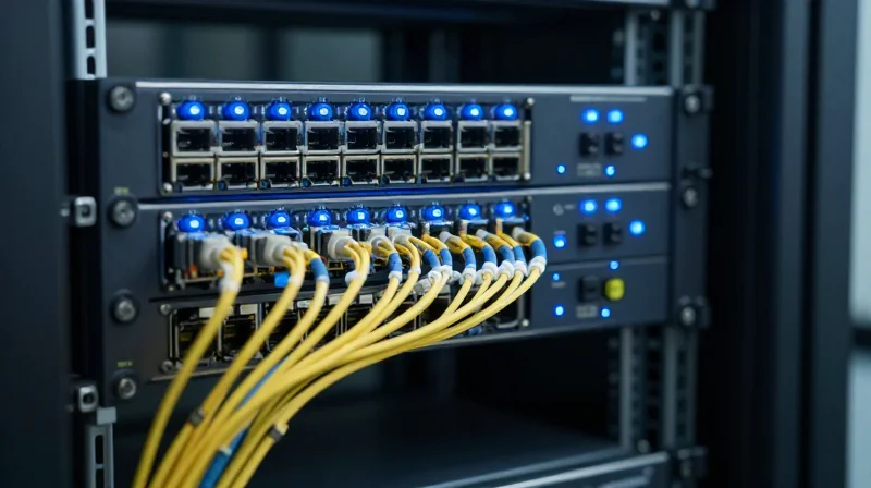
Strategic Deployment in Spine-Leaf Architectures
In modern hyperscale data centers, 200G FR4 serves as a critical link between leaf and spine switches, offering a perfect balance between reach and transceiver density. While short-reach (SR) multi-mode solutions are limited to approximately 100 meters, the 200G FR4 standard leverages single-mode fiber (SMF) to cover distances up to 2km. This capability is essential for large-scale facilities where spine switches are often located in centralized rows or separate rooms, far exceeding the physical limitations of copper or multi-mode fiber. By utilizing CWDM technology over duplex fiber, 200G FR4 reduces cabling complexity and duct congestion compared to parallel-fiber alternatives.
Campus-Scale Data Center Interconnect (DCI)
Beyond the internal fabric, 200G FR4 is an ideal solution for campus-scale DCI, where multiple data center buildings are situated within a localized area. It provides a cost-optimized alternative to 10km LR4 optics for building-to-building links that do not exceed 2km. This scenario is increasingly common as enterprises adopt modular data center designs, requiring high-bandwidth, low-latency connectivity to sync data across separate physical structures without the premium price tag of long-haul optics. The use of PAM4 modulation ensures that these 200G links maintain high spectral efficiency across the campus single-mode infrastructure.
| Deployment Type | Typical Distance | Fiber Type | Primary Advantage |
|---|---|---|---|
| Intra-DC Spine-Leaf | 500m - 2km | Duplex SMF | Reduced cabling complexity & high density |
| Campus DCI | 1km - 2km | Duplex SMF | Cost-effective building-to-building links |
| Enterprise Core | Up to 2km | Duplex SMF | Future-proofing 100G infrastructure |
Implementation Considerations
- Why is 200G FR4 preferred over SR4 for large spine-leaf fabrics?
SR4 is restricted to roughly 100m on OM4 fiber, which is often insufficient for the physical sprawl of hyperscale data centers. FR4's 2km reach on single-mode fiber ensures connectivity across the entire facility. - Can 200G FR4 be used for 400G breakout applications?
Yes, many high-density 400G switches support breaking out a 400G FR4 port into two 200G FR4 interfaces, allowing for flexible migration paths and higher port utilization. - Is there a specific fiber requirement for 200G FR4 in DCI?
200G FR4 requires standard G.652 single-mode fiber. For DCI, ensure that the total link budget, including patch panels and splices, does not exceed the transceiver's optical power limits over the 2km distance.
200G FR4 represents the perfect balance of reach, cost, and power for modern 2km optical links. By leveraging PAM4 and CWDM technologies, it provides a robust path for scalable network growth. Contact our technical specialists today to discuss your 200G migration strategy and request a demo.