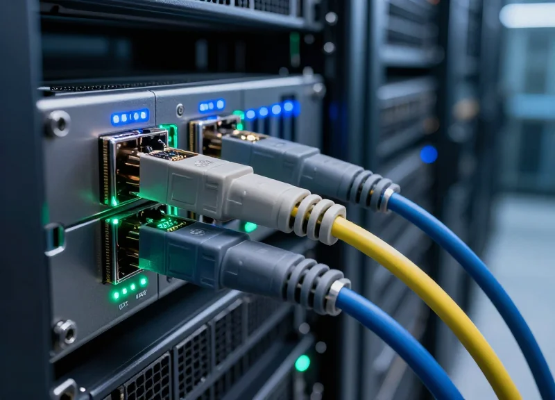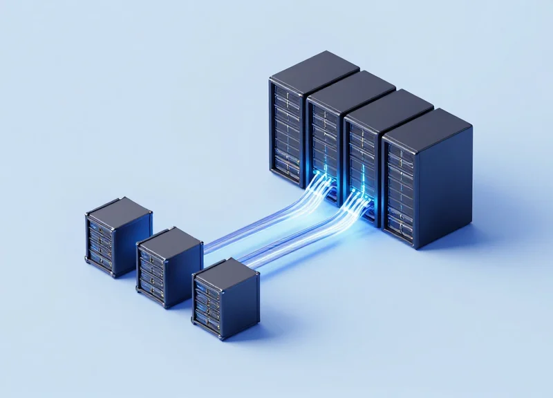
In an era where AI workloads and cloud-native applications demand unprecedented bandwidth, 400G Data Center Interconnect (DCI) has emerged as the critical backbone for modern digital infrastructure. This technical guide provides an authoritative look at the mechanisms, hardware, and protocols that allow organizations to scale their fiber capacity while maintaining efficiency.
The Evolution of DCI: Why 400G is the New Standard

The Evolution of DCI: Why 400G is the New Standard
Data Center Interconnect (DCI) 400G is the evolutionary leap from 100G infrastructure, designed to handle the exponential surge in global data traffic by providing high-density, high-throughput links between geographically dispersed data centers. As legacy 100G systems reach their physical and economic limits, 400G has emerged as the industry standard, offering the necessary spectral efficiency and power optimization required for modern hyperscale and edge computing workloads.
The Catalysts for Massive Bandwidth Expansion
The transition to 400G is primarily driven by the 'triple threat' of data growth: Artificial Intelligence, 5G proliferation, and cloud-native services. High-performance computing (HPC) clusters used for AI training require massive synchronization between nodes, while 5G and IoT have increased the volume of data moving from the edge back to the core. Legacy 100G interconnects are no longer sufficient to support these workflows without causing significant bottlenecks in data throughput and application performance.
| Feature | 100G (Legacy) | 400G (Standard) |
|---|---|---|
| Data Rate | 100 Gbps | 400 Gbps |
| Modulation Type | NRZ (Non-Return-to-Zero) | PAM4 (Pulse Amplitude Modulation 4-level) |
| Power Consumption | Higher Watts per Gigabit | Significantly Lower Watts per Gigabit |
| Port Density | Standard QSFP28 | High-Density QSFP-DD / OSFP |
Overcoming the Physical Limits of 100G
Beyond simple speed, 400G solves the technical limitations inherent in older optical technologies. For instance, scaling 100G via NRZ modulation faces severe signal integrity issues at higher frequencies. 400G utilizes PAM4 modulation, which transmits two bits per symbol, effectively doubling the data rate within the same signal bandwidth. This allows data center operators to maximize their existing fiber infrastructure while reducing the physical space and power required to move every gigabit of data.
- Why is 400G essential for AI workloads?
AI models require massive datasets to be distributed across thousands of GPUs; 400G provides the ultra-low latency and massive throughput needed to prevent data starvation in these clusters. - Does 400G reduce overall data center costs?
Yes. By increasing port density and throughput, 400G reduces the amount of hardware, cabling, and power cooling required, lowering the Total Cost of Ownership (TCO) per gigabit. - Can 400G integrate with existing 100G systems?
Modern 400G transceivers are designed for backward compatibility, often supporting breakout modes that allow a single 400G port to connect to multiple 100G legacy ports.
The Role of Coherent Optics in 400G DCI

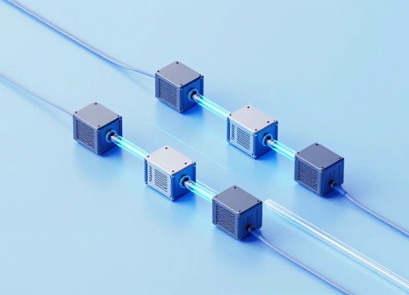
Coherent technology serves as the critical architectural foundation for 400G DCI by leveraging the phase, amplitude, and polarization of light to maximize spectral efficiency. Unlike legacy direct detection, coherent systems use a local oscillator and high-speed Digital Signal Processors (DSPs) to reconstruct the signal and electronically compensate for fiber impairments that would otherwise limit 400G performance to very short distances.
The Shift from Direct Detect to Coherent Optics
In 100G and lower eras, Intensity Modulation Direct Detection (IM-DD) was the standard. However, at 400G, the signal-to-noise ratio requirements and sensitivity to fiber dispersion make IM-DD impractical for spans beyond a few kilometers. Coherent optics solve this by using Polarization Division Multiplexing (PDM) and Quadrature Amplitude Modulation (such as 16QAM). This allows 400Gbps of data to be transmitted over a single wavelength by encoding multiple bits per symbol, significantly reducing the cost per bit over regional and long-haul distances.
The Digital Signal Processor (DSP): The Brain of 400G
The DSP is the most vital component in a 400G coherent transceiver. It performs billions of calculations per second to mitigate physical layer issues in the digital domain. Key functions of the DSP include Chromatic Dispersion (CD) compensation, Polarization Mode Dispersion (PMD) correction, and Forward Error Correction (FEC). By solving these issues mathematically, the DSP allows 400G signals to travel hundreds of kilometers without the need for expensive and signal-degrading optical dispersion compensation modules.
| Feature | Direct Detect (PAM4) | Coherent (400ZR/ZR+) |
|---|---|---|
| Typical Reach | Up to 10km | 80km to 1,000km+ |
| Spectral Efficiency | Low | High (16QAM/64QAM) |
| Dispersion Tolerance | Very Low | High (Electronic Compensation) |
| Primary Use Case | Intra-Data Center | Data Center Interconnect (DCI) |
Common Questions on 400G Coherent Technology
- What is the difference between 400ZR and 400ZR+?
400ZR is an OIF standard optimized for edge DCI links up to 120km with low power consumption. 400ZR+ is a non-standardized extension that offers higher transmit power and more robust FEC, enabling reaches well beyond 400km for regional networks. - How does polarization multiplexing work?
It doubles the data rate of a single wavelength by transmitting two independent data streams on the same frequency—one on the horizontal plane and one on the vertical plane. - Why is power consumption a concern for coherent 400G?
The high-speed DSP required for coherent detection consumes significant power. Recent advancements in 7nm and 5nm silicon manufacturing have allowed these DSPs to fit into small form factors like QSFP-DD while staying within strict thermal envelopes.
Standardization: Understanding 400G ZR and ZR+
Standardization: Understanding 400G ZR and ZR+
The 400G ecosystem is governed by two primary standards—400G ZR and 400G ZR+—which define how coherent optical signals are modulated and transmitted to meet the specific distance and throughput requirements of modern data centers. While both utilize the QSFP-DD and OSFP form factors, they differ significantly in their Forward Error Correction (FEC) schemes and target applications, effectively bifurcating the market into 'Edge DCI' and 'Regional/Long-haul' solutions.
400G ZR: The OIF Interoperability Standard
Defined by the Optical Internetworking Forum (OIF), 400G ZR was designed specifically for point-to-point, single-span links of up to 120km. Its primary goal is to provide a low-power, cost-effective, and vendor-agnostic solution that allows network operators to plug coherent transceivers directly into switches and routers. By using Concatenated Forward Error Correction (cFEC), 400G ZR achieves high spectral efficiency within a narrow power envelope, typically around 15 watts, making it ideal for high-density edge deployments.
400G ZR+: Extending Performance via OpenZR+
400G ZR+ is an industry initiative, primarily driven by the OpenZR+ Multi-Source Agreement (MSA), that expands the capabilities of the original ZR standard. By incorporating Open Forward Error Correction (oFEC) and supporting various modulation formats like QPSK and 8QAM, ZR+ modules can reach distances exceeding 500km. This standard is designed for multi-span networks with optical amplifiers and Reconfigurable Optical Add-Drop Multiplexers (ROADMs), offering a bridge between the data center edge and the long-haul core.
| Feature | 400G ZR | 400G ZR+ |
|---|---|---|
| Standard Body | OIF (Optical Internetworking Forum) | OpenZR+ MSA / Open ROADM |
| Max Reach | Up to 120 km | 480 km to 1,000+ km |
| FEC Type | cFEC (Concatenated FEC) | oFEC (Open FEC) |
| Power Consumption | ~15 Watts | 18 - 22 Watts |
| Target Network | Point-to-Point / Edge DCI | Multi-span / Regional DCI |
| Modulation | 16QAM only | QPSK, 8QAM, 16QAM |
Interoperability and Deployment Considerations
Choosing between ZR and ZR+ involves balancing power budgets and fiber infrastructure. 400G ZR offers the highest level of multi-vendor interoperability because the cFEC is strictly standardized. In contrast, while OpenZR+ aims for compatibility, the increased complexity of oFEC and the variety of adjustable bit rates (100G to 400G) require closer coordination between hardware vendors to ensure seamless integration across the optical line system.
- Can I use 400G ZR for distances over 120km?
No, 400G ZR is technically limited by its FEC gain and signal-to-noise ratio requirements to approximately 120km; for longer distances, ZR+ or LH (Long Haul) optics are required. - Why does ZR+ consume more power?
ZR+ utilizes more sophisticated Digital Signal Processing (DSP) and oFEC algorithms to maintain signal integrity over longer distances, which increases the thermal and power load on the module. - Do these modules require a separate transponder shelf?
No, both standards are designed for IP-over-DWDM, meaning they plug directly into standard QSFP-DD ports on existing switches and routers.
Form Factors: Comparing QSFP-DD and OSFP
Form Factors: Comparing QSFP-DD and OSFP
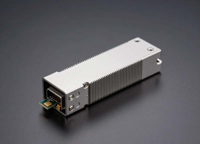
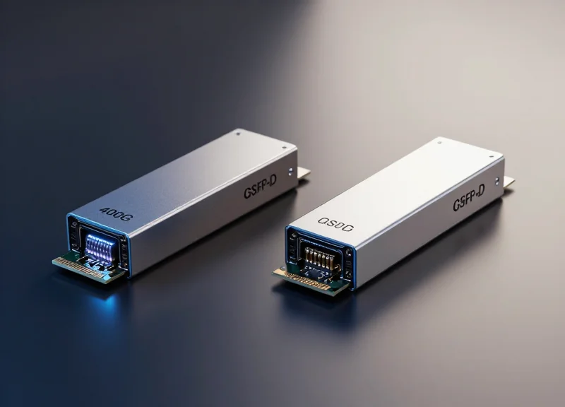
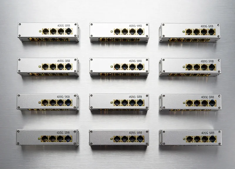
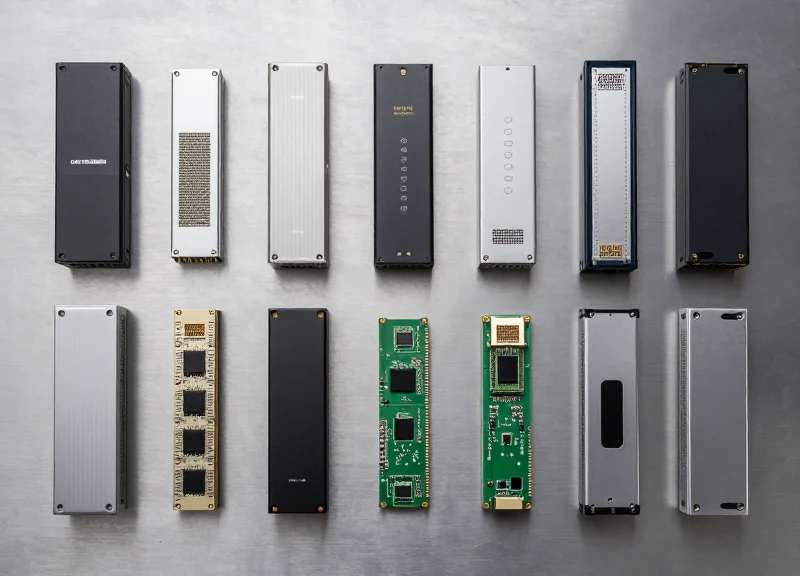
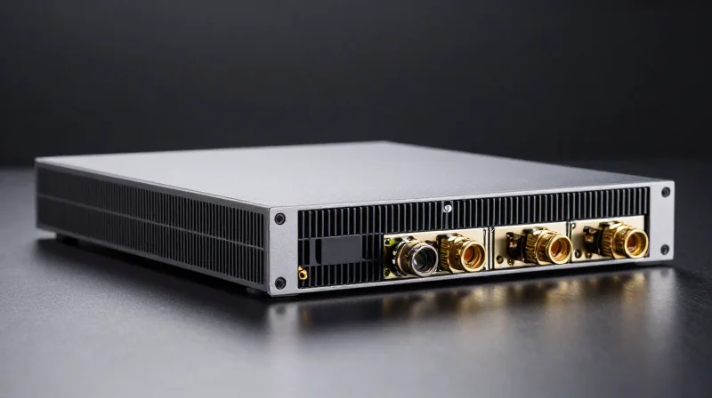
The successful deployment of 400G Data Center Interconnect (DCI) hinges on selecting the appropriate transceiver form factor, with the industry currently converging on two primary standards: QSFP-DD and OSFP. Both form factors utilize eight electrical lanes to achieve 400Gbps throughput, yet they differ significantly in their approach to thermal management, mechanical size, and backward compatibility with legacy infrastructure.
QSFP-DD: The Evolution of Density
The Quad Small Form-factor Pluggable Double Density (QSFP-DD) is the dominant choice for high-density switching environments. By adding a second row of electrical contacts to the traditional QSFP interface, it doubles the lane count from four to eight. Its most significant advantage is direct backward compatibility; a QSFP-DD port can accept standard 40G QSFP+ and 100G QSFP28 modules without a physical adapter. This preserves existing hardware investments and simplifies the migration path to 400G. However, because the heat sink is typically part of the cage rather than the module itself, thermal management for high-power 400G ZR+ optics can be more challenging compared to larger form factors.
OSFP: Engineered for Thermal Performance
The Octal Small Form-factor Pluggable (OSFP) was designed from the ground up to support the power requirements of next-generation optics. OSFP modules are slightly wider and deeper than QSFP-DD, and they feature an integrated heat sink directly on the module housing. This design allows OSFP to dissipate upwards of 15W to 20W of power, making it an ideal candidate for long-reach 400G ZR+ coherent optics and future 800G upgrades. While it is not physically backward compatible with QSFP cages, electrical compatibility can be achieved through passive adapters, allowing network operators to bridge the gap between different generations of hardware.
| Feature | QSFP-DD | OSFP |
|---|---|---|
| Electrical Lanes | 8 Lanes (50G PAM4) | 8 Lanes (50G PAM4) |
| Backward Compatibility | Direct (Supports QSFP+/QSFP28) | Requires Mechanical Adapter |
| Thermal Management | External Heat Sink (Cage-based) | Integrated Heat Sink (Module-based) |
| Max Power Envelope | Approx. 12W - 15W | Approx. 15W - 20W+ |
| Physical Dimensions | Narrower (Higher Switch Density) | Wider (Improved Cooling) |
Choosing the Right Form Factor for DCI
The decision between QSFP-DD and OSFP often depends on the specific use case within the DCI architecture. In intra-data center environments where port density and backward compatibility are paramount, QSFP-DD is the preferred standard. Conversely, for DCI applications requiring high-power coherent modules (400G ZR+) that push the limits of thermal dissipation, the OSFP’s superior cooling capabilities provide a more robust operational margin. As the industry moves toward 800G and 1.6T, the thermal architectural lessons learned from these two form factors will dictate the next phase of optical interconnect design.
FAQ: 400G Form Factor Essentials
- Can a QSFP-DD module fit into an OSFP slot?
No, they are physically incompatible. However, OSFP-to-QSFP adapters are available to allow QSFP modules to function in OSFP-equipped switches. - Which form factor is more future-proof for 800G?
While both have 800G roadmaps (QSFP800 and OSFP800), OSFP's superior thermal envelope initially gave it an edge for high-power 800G designs, though QSFP-DD has since evolved to meet those demands. - Does 400G ZR require a specific form factor?
400G ZR is available in both QSFP-DD and OSFP. The choice depends on the host equipment (router/switch) and the thermal cooling capacity of the chassis.
Architecture and Deployment Strategies

Architectural Evolution: Integrating 400G DCI into Modern Fabrics
Integrating 400G DCI into modern data centers requires a shift from traditional, siloed optical transport systems to disaggregated, pluggable-driven architectures that treat the optical layer as an extension of the routing layer. By utilizing 400G ZR and ZR+ modules, operators can bypass traditional external transponder shelves, moving the coherent modulation directly into the switch or router chassis, which simplifies the control plane and reduces hardware overhead.
The Shift to IP over DWDM (IPoDWDM)
IP over DWDM (IPoDWDM) is the primary deployment strategy for 400G DCI, characterized by the elimination of a separate optical transport layer. In this model, the router handles both the packet processing and the coherent optical transmission. This disaggregated approach allows for a 'pay-as-you-grow' model where capacity is added by simply plugging in new 400G modules. It also enables the use of open management APIs like OpenConfig, allowing the network operating system (NOS) to manage optical parameters such as frequency and transmit power directly.
| Feature | Traditional Transponder Model | Disaggregated IPoDWDM (400G) |
|---|---|---|
| Hardware Footprint | External transponder chassis (1RU-10RU) | Integrated into switch/router ports |
| Power Consumption | Higher due to dual-stage conversion | Lower (up to 40% reduction) |
| Management | Separate NMS for IP and Optical | Unified management via NOS/SDN |
| Latency | Additional latency from OEO conversion | Ultra-low, direct transmission |
Leaf-Spine and Border Leaf Topology
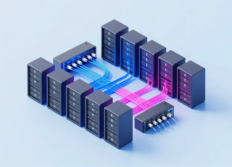
In a standard leaf-spine architecture, 400G DCI modules are typically deployed on 'Border Leaf' or 'Spine' switches. These nodes act as the gateway between the internal data center fabric and the external metro or long-haul fiber. By placing 400G ZR+ modules in spine ports, the data center can achieve high-density interconnection without specialized external equipment. This topology supports massive horizontal scaling, where additional 400G links can be bonded via ECMP (Equal-Cost Multi-Pathing) to provide terabits of inter-site throughput.
Deployment Considerations and FAQs
- How does 400G DCI impact thermal management in switches?
400G coherent modules (QSFP-DD/OSFP) consume significantly more power (up to 15-20W) than standard client-side optics. Switches must be designed with enhanced cooling and specialized cages to prevent thermal throttling of the DSP. - Is an Optical Line System (OLS) still required with 400G ZR?
Yes, while the transponder is eliminated, an 'Open Line System' (amplifiers, MUX/DEMUX, and ROADMs) is still necessary to multiplex multiple 400G wavelengths onto a single fiber pair and provide the necessary gain for longer spans. - Can I mix different vendors' 400G ZR modules in the same link?
One of the primary goals of the OIF 400G ZR standard is interoperability. Provided both vendors adhere to the same Forward Error Correction (cFEC) and modulation specifications, multivendor links are achievable, unlike previous generations of proprietary coherent systems.
Power Efficiency and Thermal Management Challenges
The 400G Thermal Wall: Power Efficiency and Heat Management
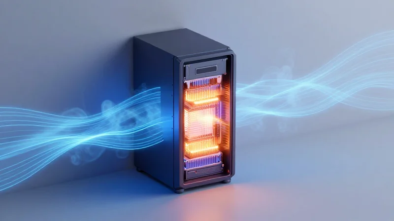
The transition to 400G Data Center Interconnect (DCI) represents a significant leap in bandwidth, but it also approaches a 'thermal wall' where the power density of pluggable modules threatens to exceed standard air-cooling capabilities. While 400G technology drastically reduces the power consumption per bit compared to 100G, the absolute power draw per module has surged from approximately 3.5W–5W in QSFP28 to upwards of 15W–22W in 400G ZR/ZR+ modules. Managing this heat is not merely an operational cost concern; it is a fundamental requirement for maintaining signal integrity and hardware longevity in high-density leaf-spine architectures.
DSP Miniaturization: 7nm and 5nm CMOS Nodes
The primary driver of power efficiency in 400G optics is the Digital Signal Processor (DSP). The move from 16nm to 7nm, and recently to 5nm CMOS process nodes, has been essential for fitting the complex coherent processing required for DCI into a compact pluggable form factor. These smaller process nodes allow for higher transistor density and lower switching voltage, which directly reduces the 'Watts per Gigabit' metric. However, as DSPs shrink, the heat produced is concentrated in a smaller surface area, necessitating sophisticated thermal interface materials (TIM) and heat sink designs within the transceiver housing.
| Module Type | Typical Power Consumption | Cooling Requirement | Efficiency (W/Gbps) |
|---|---|---|---|
| 400G DR4 (Intra-DC) | 10W - 12W | Standard Airflow | 0.025 - 0.03 |
| 400G ZR (DCI) | 15W - 18W | Enhanced Airflow/Heatsinks | 0.037 - 0.045 |
| 400G ZR+ (Long Haul) | 18W - 22W+ | Advanced Thermal Management | 0.045 - 0.055 |
| Legacy 100G LR4 | 3.5W - 4.5W | Standard Airflow | 0.035 - 0.045 |
Physical Cooling Challenges: OSFP vs. QSFP-DD
The choice of form factor is often a thermal decision. The OSFP (Octal Small Form-factor Pluggable) was designed with integrated heat fins, making it capable of dissipating up to 15W–20W effectively. In contrast, the QSFP-DD (Quad Small Form-factor Pluggable Double Density) relies more heavily on the cage and the system-level cooling of the switch. For high-density 400G ZR+ deployments, engineers must ensure that the front-to-back airflow is sufficient to prevent thermal throttling, which can occur if the DSP temperature exceeds 85°C–90°C, leading to increased bit error rates (BER).
- How does 400G improve power efficiency compared to 100G?
400G modules utilize more advanced DSPs and higher-order modulation (16QAM), which allows them to transmit four times the data with only approximately three times the power, resulting in a 20-30% improvement in energy efficiency per bit. - What are the risks of inadequate thermal management in 400G DCI?
Inadequate cooling leads to 'thermal runaway,' where increased heat raises the electrical resistance, further increasing heat. This causes laser frequency instability, DSP errors, and eventually an automatic shutdown of the port to protect the switch silicon. - Can existing 100G cooling systems handle 400G modules?
Generally, no. A rack filled with 400G modules requires significantly higher CFM (Cubic Feet per Minute) of airflow and often requires switches with improved baffle designs and high-RPM fans to overcome the increased thermal load.
Network Performance: Latency and Error Correction
The Critical Balance: Latency vs. Error Correction in 400G DCI
In 400G Data Center Interconnect (DCI) architectures, maintaining performance requires a sophisticated trade-off between Forward Error Correction (FEC) overhead and processing latency. Because 400G utilize PAM4 (Pulse Amplitude Modulation 4-level) signaling, which is inherently more susceptible to noise than the NRZ signaling used in 100G, advanced error correction is mandatory to ensure a bit error rate (BER) suitable for mission-critical applications. This is achieved through highly optimized Digital Signal Processors (DSPs) that implement algorithms like KP4 and OpenFEC, designed to provide substantial coding gains while keeping the 'latency tax' within nanosecond thresholds.
Forward Error Correction (FEC) Architectures
FEC is the primary mechanism for correcting transmission errors without requiring retransmissions, which would be catastrophic for DCI latency. In 400G systems, the industry has standardized on several FEC variants depending on the reach and the transceiver type. While KP4 FEC (defined by IEEE 802.3bs) is standard for shorter-reach intra-DC and campus links, coherent 400G ZR/ZR+ modules often employ more robust algorithms like oFEC (OpenFEC) to handle the optical impairments of longer fiber spans.
| FEC Algorithm | Standard Context | Typical Latency | Net Coding Gain (NCG) |
|---|---|---|---|
| KP4 (RS-FEC) | IEEE 802.3bs / 400G Ethernet | ~100 ns - 150 ns | ~9.1 dB |
| oFEC (OpenFEC) | OpenROADM / 400G ZR+ | ~15 μs - 20 μs | ~11.6 dB |
| CFEC | OIF 400G ZR | ~5 μs - 10 μs | ~10.8 dB |
Minimizing Latency for Mission-Critical Applications
For latency-sensitive workloads like high-frequency trading or real-time AI inference, the cumulative delay of the DCI link is paramount. Performance optimization in 400G DCI focuses on three areas: reducing DSP serialization delay, optimizing the optical-to-electrical conversion, and selecting the right FEC profile. While long-haul 400G requires heavy FEC that adds microseconds of delay, metro-DCI deployments often favor 'light' FEC settings or bypass certain DSP functions to maintain a lower latency profile, often referred to as 'Low Latency Mode' in high-end transceivers.
- Why is FEC mandatory for 400G DCI?
400G uses PAM4 signaling which reduces the signal-to-noise ratio margin. Without FEC, the raw bit error rate would be too high for reliable data transmission over even short distances. - Does 400G ZR+ add more latency than 400G ZR?
Generally, yes. 400G ZR+ often uses more complex FEC algorithms like oFEC to achieve longer distances, which involves more intensive processing and higher latency compared to the CFEC used in standard ZR. - How does fiber distance impact latency relative to FEC?
Fiber latency is constant at roughly 5 microseconds per kilometer. For short-reach DCI, FEC latency is a significant percentage of the total budget; for long-haul, the fiber propagation delay dominates the latency profile.
Future-Proofing: Preparing for 800G and Beyond
Modern 400G DCI deployments serve as the essential technical foundation for the high-baud-rate electronics and coherent DSP technologies that will define the 800G and 1.6T eras. By mastering the complexities of 400G—specifically in areas like Forward Error Correction (FEC) and thermal management—operators establish a modular framework that allows for future-proofing through incremental hardware upgrades rather than complete architectural overhauls.
The Technical Evolution: From 400G to Terabit Networking
The leap to 800G is primarily driven by the evolution of SerDes (Serializer/Deserializer) technology, moving from 56G to 112G and eventually 224G lanes. This progression allows for higher density in the same physical footprint, utilizing form factors like OSFP (Octal Small Form-factor Pluggable) and QSFP-DD that were refined during the 400G adoption cycle. As the industry moves toward 800G-ZR and 800G-ZR+, the reliance on 5nm and 3nm CMOS process nodes becomes critical to keep power consumption within manageable limits for pluggable modules.
| Feature | 400G (Current) | 800G (Emerging) | 1.6T (Future) |
|---|---|---|---|
| Typical Baud Rate | 60-90 GBaud | 90-120 GBaud | 180+ GBaud |
| Modulation Scheme | 16QAM / 32QAM | 64QAM / 16QAM | 64QAM+ |
| Standard Form Factor | QSFP-DD / OSFP | OSFP800 / QSFP-DD800 | OSFP1600 |
| DSP Node Architecture | 7nm / 5nm | 5nm / 3nm | 3nm / 2nm |
Strategic Foundations for Scale
To effectively future-proof data center interconnects, operators must focus on spectral efficiency and fiber plant quality. As baud rates increase, signal sensitivity to fiber impairments like Chromatic Dispersion (CD) and Polarization Mode Dispersion (PMD) grows exponentially. Consequently, investments in high-quality G.652.D or G.654.E fiber today are essential prerequisites for supporting the 800G and 1.6T coherent signals of tomorrow. Furthermore, the move toward IP over DWDM (IPoDWDM) at 400G simplifies the control plane, making it significantly easier to integrate higher-speed optics as they become commercially viable.
Common Questions on Future-Proofing DCI
- Will my existing 400G fiber plant support 800G?
In most cases, yes. However, 800G requires a higher Optical Signal-to-Noise Ratio (OSNR). If your current fiber spans are reaching their limit at 400G, you may need to implement more advanced amplification or Raman pumping for 800G. - What is the primary driver for moving beyond 400G?
The main drivers are the reduction of cost-per-bit and power-per-bit. While 400G is currently the 'sweet spot,' 800G provides double the density in the same rack space, which is critical for AI/ML workloads. - Are 400G and 800G optics interoperable?
Direct interoperability depends on the modulation and FEC settings. While most 800G ports can break down into 2x400G streams, a native 800G signal cannot be read by a legacy 400G-only DSP.
Navigating the shift to 400G DCI is essential for staying competitive in a data-driven market. By understanding the interplay between coherent optics and hardware standards, organizations can build resilient, high-capacity networks. Ready to optimize your infrastructure? Contact our technical consultants for a tailored 400G migration plan.