As data rates accelerate toward 800G and 1.6T, the thermal density of optical modules has become a critical bottleneck in network performance. This article provides a comprehensive technical analysis of how engineers manage heat to prevent signal degradation and hardware failure.
The Evolution of Thermal Density in Optical Modules
The Rising Thermal Challenge in Optical Networking
The evolution of optical modules is characterized by a relentless pursuit of higher bandwidth within standardized, compact form factors, which has led to an exponential increase in power density. As data rates have scaled from 10Gbps to 800Gbps, the energy required to process and transmit data has surged, transforming optical transceivers from simple passive components into high-performance computing devices that generate significant waste heat. This transition necessitates a fundamental shift from basic airflow cooling to sophisticated heat dissipation management strategies to ensure long-term reliability and performance.
Tracking Power Scaling Across Module Generations
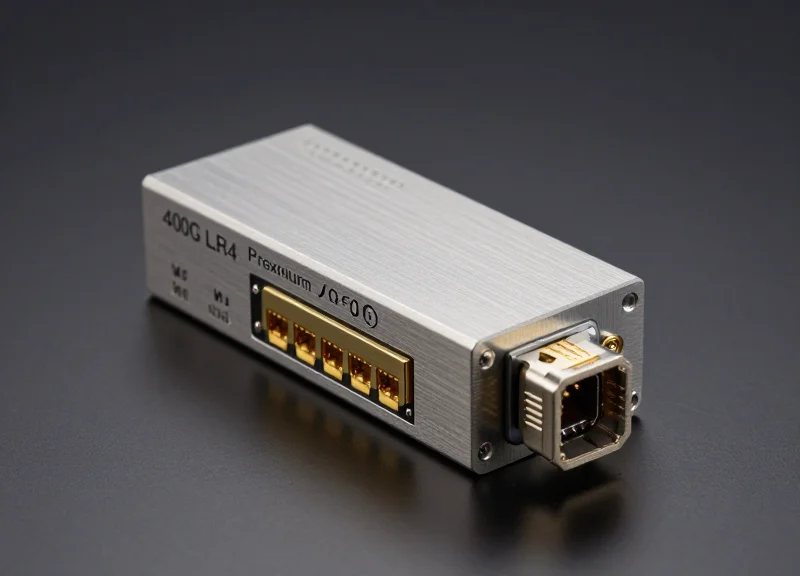
Early 10G SFP+ modules operated with a power envelope of approximately 1W, meaning heat dissipation was rarely a design bottleneck. However, the introduction of PAM4 modulation and the integration of sophisticated Digital Signal Processors (DSPs) in 400G and 800G modules have pushed power consumption to 20W or more. Because the physical dimensions of these modules (like the QSFP-DD) remain relatively fixed to maintain backward compatibility and density, the heat flux per square centimeter has reached levels comparable to high-end CPUs.
| Module Standard | Max Data Rate | Typical Power (W) | Thermal Management Complexity |
|---|---|---|---|
| SFP+ | 10G | 1.0 - 1.5W | Low |
| QSFP+ | 40G | 3.5W | Moderate |
| QSFP28 | 100G | 4.5 - 6W | Moderate-High |
| QSFP-DD / OSFP | 400G | 12 - 14W | High |
| OSFP / QSFP-DD800 | 800G | 16 - 24W | Extreme |
Key Drivers of Heat Density
- Why has power consumption increased so drastically in 800G modules?
The primary driver is the DSP (Digital Signal Processor). At 800G, the DSP must handle complex error correction and signal compensation at extremely high baud rates, requiring billions of transistors to switch at picosecond intervals. - How does form factor impact thermal density?
Form factors like QSFP-DD provide a very small surface area for cooling. When 24W of power is concentrated in such a small volume, the 'heat flux'—the rate of heat energy transfer through a surface—becomes difficult to manage without advanced thermal interface materials (TIMs) and integrated heatsinks. - What are the risks of poor heat dissipation?
Excessive heat leads to laser wavelength shifting, which causes signal degradation. Furthermore, high temperatures accelerate the aging of internal components, significantly reducing the Mean Time Between Failures (MTBF).
In the modern data center environment, managing this evolution in thermal density is no longer optional. System architects must now design around the thermal limits of the modules, employing specialized cage designs, high-performance fans, and even liquid cooling solutions to keep internal temperatures within the operational window of 0%C to 70%C.
Core Mechanics of Heat Generation in Transceivers
Core Mechanics of Heat Generation in Transceivers
Heat generation in optical transceivers is a physical manifestation of energy loss during the high-speed processing of electrical and optical signals. This thermal output is primarily driven by resistive losses in the copper traces and the active power requirements of the integrated circuits responsible for signal conditioning, modulation, and error correction. As data rates scale toward 800G and 1.6T, the density of these operations within the constrained volume of the module creates intense thermal flux that can compromise performance if not managed via advanced dissipation techniques.
The DSP: The Central Thermal Engine
The Digital Signal Processor (DSP) is the dominant heat source in high-capacity modules like the 400G QSFP56-DD and 800G OSFP. It performs the intensive computational tasks required for PAM4 (Pulse Amplitude Modulation 4-level) signaling and complex Forward Error Correction (FEC). These operations require billions of transistor switches per second, resulting in high dynamic power consumption. In an 800G transceiver, the DSP can account for over 60% of the total thermal budget, necessitating high-performance thermal interface materials (TIM) to bridge the gap to the module housing.
Optical Sub-Assemblies and Drivers
Beyond the DSP, the Transmitter Optical Sub-Assembly (TOSA) and the Laser Driver are critical thermal contributors. The driver converts the DSP output into a high-current signal to modulate the laser. The laser itself, whether an EML (Electro-absorption Modulated Laser) or DML (Directly Modulated Laser), generates heat through electrical resistance and photon emission inefficiencies. In coherent modules, a Thermo-Electric Cooler (TEC) is often employed to stabilize the laser wavelength, which paradoxically consumes additional electrical power and generates extra heat that must be extracted from the module.
| Component | Primary Role | Estimated Thermal Contribution |
|---|---|---|
| DSP | Signal processing and FEC | 55% - 70% |
| Laser Driver | Laser modulation current | 10% - 15% |
| TOSA / ROSA | Optical/Electrical conversion | 15% - 20% |
| TEC / Passive | Thermal control and filtering | 5% - 10% |
- Why does the DSP generate the most heat?
The DSP manages high-frequency transformations on millions of data bits simultaneously to ensure signal integrity, requiring massive power density within a small silicon area. - How does the laser driver contribute to the thermal load?
The driver must deliver high-speed, high-amplitude electrical currents to the laser, leading to significant Joule heating within the driver circuitry. - What is the impact of a Thermo-Electric Cooler (TEC) on heat?
While a TEC cools the laser diode, it is an active component that generates its own heat as a byproduct of the Peltier effect, increasing the overall module temperature.
Thermal Interface Materials (TIMs) and Their Applications
The Vital Role of TIMs in Module Heat Dissipation Management
In the context of module heat dissipation management, Thermal Interface Materials (TIMs) are substances applied between the heat source—such as a DSP or Laser Driver—and the module's heat sink or outer casing. Because even the most polished metal surfaces possess microscopic irregularities, air becomes trapped at the junction. Since air is a poor thermal conductor (approx. 0.026 W/m·K), it creates significant thermal resistance. TIMs are engineered to displace this air and provide a high-conductivity pathway, effectively 'thermalizing' the interface and allowing heat to flow seamlessly from the silicon to the external environment.
Comparative Analysis of Common TIM Categories
| TIM Type | Thermal Conductivity (W/m·K) | Primary Advantage | Application Scenario |
|---|---|---|---|
| Thermal Grease | 3.0 - 10.0 | Lowest Bond Line Thickness (BLT) | R&D and characterization testing |
| Phase Change Materials (PCM) | 3.0 - 8.0 | Superior long-term stability | High-volume 400G/800G production |
| Thermal Pads | 1.0 - 17.0 | Ease of handling and rework | Bridging large mechanical tolerances |
| Gap Fillers | 2.0 - 12.0 | Low stress on fragile components | Automated liquid dispensing lines |
Critical Performance Factors for Optical Modules
When selecting a TIM for high-density modules like 800G QSFP-DD, engineers must prioritize more than just bulk thermal conductivity. The Thermal Impedance—which combines bulk resistance and contact resistance—is the true metric of performance. For optical transceivers, 'outgassing' is a deal-breaker; traditional silicone-based TIMs can release volatile organic compounds that deposit onto sensitive optical facets, causing signal attenuation. Consequently, high-performance, non-silicone materials are becoming the industry standard to ensure both thermal efficiency and optical integrity.
Common Integration Challenges and Solutions
- How does Bond Line Thickness (BLT) affect heat dissipation?
The thinner the layer of TIM, the lower the thermal resistance. However, the material must be thick enough to compensate for component height variations and PCB warpage without creating voids. - What is the 'Pump-out' effect in thermal greases?
Pump-out occurs when repeated thermal expansion and contraction cycles squeeze the grease out of the interface. This is why Phase Change Materials (PCMs) are preferred for long-term reliability, as they transition to a solid-state at room temperature. - Why is assembly pressure critical for TIM performance?
TIMs require a specific amount of compressive force to wet the surfaces and reach their optimal thermal impedance. Inadequate pressure leads to trapped air, while excessive pressure can damage the DSP or flip-chip bonds.
Advanced Cooling Architectures: Active vs. Passive
Advanced Cooling Architectures: Active vs. Passive
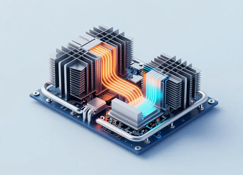
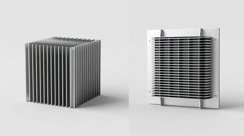
Effective module heat dissipation management relies on a strategic choice between passive architectures, which utilize natural conduction and convection, and active architectures, which apply external energy to forcibly move heat. While passive cooling remains the industry standard for lower-power modules due to its reliability and zero energy cost, the advent of 800G and 1.6T modules—where power densities exceed 20W per pluggable unit—is driving the adoption of active thermal management to prevent junction temperatures from exceeding critical thresholds.
Passive Cooling: Reliability Through Surface Engineering
Passive cooling systems consist of heat sinks, heat spreaders, and the module housing itself. These components are designed with high-conductivity metals like aluminum or copper alloys to maximize the surface area exposed to the chassis-level airflow. In the context of module heat dissipation management, the efficiency of a passive system is dictated by the thermal resistance of the materials and the fin geometry. For modules up to 400G (QSFP-DD/OSFP), passive cooling is often sufficient, provided the host system's fan speed and airflow pathing are optimized.
Active Cooling: Precision Temperature Control
Active cooling introduces components like Thermoelectric Coolers (TEC) and micro-fans directly into the module architecture. A TEC uses the Peltier effect to create a heat flux between the junction of two different types of materials, effectively 'pumping' heat away from the laser diode or DSP. This is critical for temperature-sensitive components like Electro-absorption Modulated Lasers (EML) and silicon photonics circuits, where even a slight temperature drift can cause wavelength shifts and signal degradation. While active cooling offers sub-ambient temperature control, it adds to the overall power budget and complexity of the transceiver.
| Feature | Passive Cooling | Active Cooling (TEC/Micro-fans) |
|---|---|---|
| Power Consumption | Zero (0W) | High (adds 1W to 3W+) |
| Complexity | Low (structural design) | High (requires control circuitry) |
| Temperature Control | Ambient dependent | Precision/Sub-ambient possible |
| Reliability (MTBF) | Exceptionally high | Moderate (active parts can fail) |
| Typical Application | 10G - 400G Transceivers | High-power 800G+ and Coherent Optics |
Strategic Implementation in High-Density Environments
- When is active cooling mandatory?
Active cooling is required when the component junction temperature exceeds safe operating limits despite maximum passive airflow, or when wavelength stability (DWDM) requires precise thermal regulation. - How does active cooling impact the 'Power Envelope'?
Active cooling increases the total power consumption of the module, which can limit the port density of a switch if the total power budget or the cooling capacity of the chassis is exceeded. - Can passive cooling be improved without moving to active?
Yes, by utilizing vapor chambers, heat pipes, or graphene-based heat spreaders, the thermal conductivity of passive systems can be significantly enhanced to delay the need for active components.
The Impact of Form Factors: QSFP-DD vs. OSFP
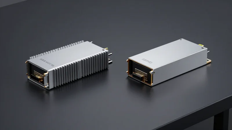
Module heat dissipation management is fundamentally constrained or enabled by the form factor's mechanical design; while QSFP-DD focuses on density and backward compatibility, the OSFP (Octal Small Form-factor Pluggable) architecture was specifically engineered to address the thermal demands of high-power 800G and 1.6T transceivers through integrated cooling structures.
QSFP-DD: Balancing Density with External Cooling
The Double Density Quad Small Form-factor Pluggable (QSFP-DD) maintains compatibility with legacy QSFP ports, which is its primary market advantage. However, from a thermal perspective, QSFP-DD relies on the host system’s heat sink to make contact with the flat top surface of the module. This creates a thermal interface bottleneck, as the heat must pass through the module shell and then into the host’s cooling solution. As power consumption rises toward 15W-20W per module, managing the contact pressure and thermal resistance at this interface becomes a critical engineering challenge.
OSFP: The Integrated Heat Sink Advantage
OSFP was designed from the ground up to handle higher power envelopes. Its most distinctive feature is the integrated heat sink—fins built directly into the module’s casing. This allows for direct airflow across the fins, significantly reducing thermal resistance. By eliminating the need for a separate host-side heat sink to provide the primary cooling, OSFP can dissipate significantly more heat (targeting 15W to 30W) without exceeding safe operating temperatures for the sensitive Digital Signal Processor (DSP) and laser components inside.
| Feature | QSFP-DD | OSFP |
|---|---|---|
| Thermal Path | External (Flat Top Contact) | Integrated (Finned Top) |
| Typical Power Limit | 12W - 15W (Standard Airflow) | Up to 30W |
| Module Size | Narrower (Higher Density) | Wider/Taller (Higher Surface Area) |
| Backward Compatibility | Native (QSFP+/QSFP28) | Requires Adapter |
Mechanical Impact on Airflow Resistance
Because OSFP modules are slightly wider and taller, they accommodate larger internal components and better airflow pathways. The integrated fins on the OSFP design not only increase the surface area for convection but also allow system designers to optimize chassis-level airflow. In contrast, QSFP-DD systems often require high-pressure cooling environments to force enough air across the host-side heat sinks, which can lead to higher acoustic noise and increased fan power consumption at the data center level.
- Which form factor is better for 800G networks?
OSFP is generally preferred for 800G and 1.6T applications due to its superior thermal headroom, though QSFP-DD800 remains a viable option for legacy-heavy environments with robust cooling. - Does OSFP require special host hardware?
Yes, OSFP requires a specific cage and connector that is larger than the QSFP standard, which affects port density on the switch faceplate. - Why is thermal resistance lower in OSFP?
The integration of fins directly into the module housing eliminates one of the thermal interface layers (the gap between module and host sink) found in QSFP-DD, allowing for more efficient heat transfer to ambient air.
Software-Defined Thermal Management and Monitoring

Software-defined thermal management (SDTM) is the intelligence layer that complements physical heat dissipation hardware by using firmware-driven logic to monitor, report, and mitigate thermal risks in real-time. Unlike traditional passive cooling, which relies solely on the physical design of the module and heat sink, SDTM allows the system to dynamically adjust its operational parameters to prevent hardware degradation and maintain link stability under varying environmental conditions.
Digital Diagnostic Monitoring (DDM) and the I2C Interface
At the heart of software-defined management is the I2C (Inter-Integrated Circuit) serial bus, which serves as the primary communication link between the optical module and the host switch or router. Through the Digital Diagnostic Monitoring (DDM) interface—standardized under SFF-8472—the host can access internal module registers that store live telemetry data, including internal temperature, laser bias current, and supply voltage. This data is updated in milliseconds, providing a granular view of the module's thermal state.
| Feature | Static Thermal Management | Software-Defined Management |
|---|---|---|
| Control Logic | Fixed hardware design | Dynamic firmware algorithms |
| Response Type | Passive dissipation | Active throttling and alerting |
| Data Feedback | None | Real-time DDM telemetry |
| Power Efficiency | Constant power draw | Power-optimized based on heat |
Real-Time Thermal Throttling and Protection
When internal sensors detect that the module has exceeded its defined 'High Temp Alarm' threshold, the software layer initiates protective measures. Thermal throttling involves reducing the power consumption of the Digital Signal Processor (DSP) or lowering the laser bias current to reduce heat generation at the source. In extreme cases, the host software may trigger an emergency shutdown of the port to prevent irreversible damage to the laser diode or integrated circuits (ICs).
/* Example Pseudocode: Thermal Threshold Logic */
if (ddm_temp >= TEMP_ALARM_LIMIT) {
    trigger_alert("CRITICAL_TEMP");
    set_power_mode("LOW_POWER");
    reduce_data_rate();
} else if (ddm_temp >= TEMP_WARN_LIMIT) {
    increase_fan_speed_host();
}
Common Questions on Software-Defined Thermal Control
- How does I2C speed affect thermal management?
Standard I2C (100kHz) or Fast Mode (400kHz) is sufficient for thermal monitoring because temperature changes in optical modules occur over seconds, not microseconds, allowing the host to respond well within the thermal time constant. - Can the host switch control the module's internal cooling?
While the host cannot directly control the module's internal components, it can use DDM data to increase external fan speeds or signal the module to enter a lower-power state via the I2C interface. - What is the difference between a Thermal Warning and a Thermal Alarm?
A Warning indicates the module is reaching its operational limit and requires increased external cooling, while an Alarm indicates the module is at risk of damage and software must take immediate action to reduce power.
Common Failure Modes and Reliability Concerns
Common Failure Modes and Reliability Concerns
In high-density data center environments, thermal mismanagement is the primary catalyst for accelerated aging and catastrophic failure of optical transceivers. When heat dissipation fails to keep the junction temperature within specified limits—typically 0°C to 70°C for commercial grade or up to 85°C for industrial grade—the module undergoes irreversible physical and chemical changes. These failures range from subtle signal degradation that increases Bit Error Rates (BER) to complete hardware shutdowns caused by thermal runaway.
Laser Degradation and Quantum Efficiency
The semiconductor laser (EML or DML) is the most temperature-sensitive component in a module. Excessive heat leads to an increase in the threshold current ($I_{th}$), the minimum current required to achieve lasing. As the temperature rises, the slope efficiency—representing the conversion of electrical current into optical power—decreases significantly. This degradation is often accelerated by the migration of defects within the crystal lattice, a process known as non-radiative recombination, which eventually renders the laser incapable of meeting the required optical output power for error-free transmission.
Wavelength Drift and Spectral Instability
In Wavelength Division Multiplexing (WDM) systems, precise wavelength control is vital for channel spacing. Heat alters the refractive index of the laser’s active region and the physical dimensions of the optical cavity. This causes the emission wavelength to shift (drift), usually at a rate of approximately 0.1 nm per degree Celsius. Without robust heat dissipation or active TEC control, a module’s wavelength may drift into an adjacent channel’s spectrum, causing massive inter-channel crosstalk and systemic link failure.
| Failure Mode | Primary Thermal Cause | Operational Impact |
|---|---|---|
| Wavelength Drift | Refractive index changes due to heat | Crosstalk in WDM systems, link loss |
| Threshold Current Rise | Non-radiative recombination increase | Reduced optical power, increased power consumption |
| Solder Fatigue | CTE mismatch during thermal cycling | Intermittent connectivity, open circuits |
| Dark Line Defects | High junction temperature stress | Permanent laser failure, sudden death |
Material Fatigue and CTE Mismatch
Reliability is also compromised by the mechanical stress of thermal cycling. Optical modules are composed of diverse materials, including silicon, gold, ceramics, and polymers, each with a different Coefficient of Thermal Expansion (CTE). Repeated heating and cooling cycles cause these materials to expand and contract at different rates, leading to solder joint fatigue, delamination of optical coatings, and misalignment of the micro-optical sub-assemblies (TOSA/ROSA). Even a sub-micron shift in lens alignment due to thermal expansion can lead to a 3dB loss in coupled power.
- How does heat affect the lifespan of a laser?
The Arrhenius equation governs laser aging; every 10°C increase in operating temperature approximately halves the Mean Time To Failure (MTTF) of the semiconductor laser component. - What is 'Thermal Runaway' in optical modules?
It occurs when rising temperatures increase the power consumption of internal components (like the DSP or TEC), which in turn generates more heat, exceeding the module's cooling capacity and leading to immediate hardware failure. - Can software monitoring prevent these failures?
Yes, by using Digital Diagnostic Monitoring (DDM) to trigger thermal throttling or 'soft' shutdowns before the components reach the absolute maximum temperature ratings.
Liquid Cooling and Immersion Trends in Optical Networking
Liquid Cooling and Immersion Trends in Optical Networking
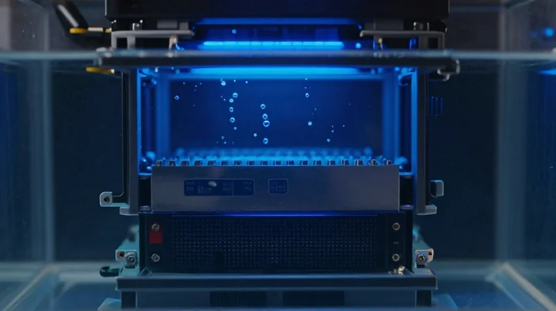
Liquid cooling represents the next frontier in module heat dissipation management, providing a necessary solution as 800G and 1.6T transceivers push power envelopes beyond the 25-30W threshold where traditional forced-air systems lose efficiency. By leveraging the significantly higher thermal conductivity of fluids compared to air, data center operators can maintain optimal junction temperatures for lasers and DSPs even in ultra-high-density rack configurations.
The Shift from Air-Cooled to Liquid-Cooled Ecosystems
As rack power densities climb toward 50kW and beyond, air-cooling systems struggle with the volume of airflow required and the resulting acoustic noise and energy consumption of high-speed fans. Modern heat dissipation management is pivoting toward two primary liquid-based strategies: Direct-to-Chip (Cold Plate) cooling and Single-Phase or Two-Phase Immersion cooling. In a cold plate setup, a liquid-filled manifold makes contact with the module's cage, while immersion involves submerging the entire switch and its optics in a dielectric fluid. These methods eliminate the 'thermal bottleneck' at the module-to-air interface, allowing for much tighter component spacing and more stable operating environments.
| Cooling Method | Heat Transfer Efficiency | Infrastructure Complexity | Max Rack Power Support |
|---|---|---|---|
| Forced Air | Low | Low | Up to 20-25 kW |
| Cold Plate (Liquid-to-Chip) | High | Moderate | 50 - 100 kW |
| Single-Phase Immersion | Very High | High | 100+ kW |
| Two-Phase Immersion | Highest | Very High | 200+ kW |
Material Compatibility and Design Considerations
Transitioning to liquid cooling requires a fundamental rethink of transceiver materials. In immersion environments, the dielectric fluid must be chemically compatible with the module's plastics, adhesives, and gold plating to prevent leaching or corrosion. Furthermore, traditional 'open' module designs like the standard QSFP-DD may need modifications to allow fluid flow or, conversely, to ensure hermetic sealing if the internal optical path must remain dry. The OSFP form factor, with its integrated heat sink, is often viewed as more adaptable to these liquid-cooled environments due to its robust mechanical shell and superior surface area for fluid contact.
- Why is liquid cooling becoming mandatory for 1.6T optics?
At 1.6T speeds, the heat flux generated by the DSP and TOSA/ROSA components exceeds the capacity of air to carry heat away without reaching dangerous internal temperatures that cause laser failure. - Does immersion cooling affect optical signal integrity?
If fluid enters the optical path of a non-hermetic module, it can change the refractive index and cause signal loss; therefore, immersion-ready modules must be specially sealed or use 'blind-mate' liquid connectors. - What is the primary benefit of cold plate cooling over immersion?
Cold plate cooling allows for easier maintenance and 'hot-swapping' of modules compared to immersion, which requires handling fluid-covered hardware and specialized tanks.
Silicon Photonics: A Paradigm Shift in Heat Management
Silicon photonics represents a fundamental shift in optical module architecture by leveraging semiconductor manufacturing processes to integrate lasers, modulators, and detectors directly onto a silicon substrate. This integration addresses the primary thermal bottleneck of traditional pluggable modules—the electrical-to-optical conversion loss—by minimizing the distance between electronic circuits and optical engines. By reducing signal degradation and the need for power-hungry re-timers, silicon photonics lowers the overall thermal envelope while streamlining the path from heat source to heat sink.
The Architectural Transition: Beyond Discrete Components
In conventional transceiver designs, discrete components are mounted on a PCB, leading to significant parasitic energy loss and heat generation as high-speed electrical signals travel through traces and connectors. Silicon photonics enables Co-Packaged Optics (CPO), where the optical engine is placed in the same package as the switch ASIC. This proximity eliminates the need for complex signal conditioning (like DSPs or CDRs) for every millimeter of travel, removing the largest heat generators within a module.
| Feature | Traditional Pluggable Modules | Silicon Photonics / CPO |
|---|---|---|
| Signal Path Distance | Long (Multiple inches of PCB) | Short (Millimeters/Microns) |
| Thermal Resistance | High (Multi-layer interface) | Low (Direct silicon contact) |
| Power Efficiency | ~25-30 pJ/bit | Under 10 pJ/bit |
| Heat Distribution | Scattered across many ICs | Concentrated and predictable |
Simplified Thermal Paths and Reliability
- How does integration reduce the thermal footprint?
Monolithic integration reduces the number of physical interfaces that heat must cross. By having modulators and detectors on the same die as the drivers, the system minimizes electrical resistance and eliminates redundant power supplies. - What is the impact on laser thermal stability?
Silicon photonics allows for the use of external laser sources (ELS). By moving the heat-sensitive laser away from the high-temperature ASIC area, thermal management becomes easier, and the laser's lifespan is significantly extended. - Can silicon photonics handle 1.6T and beyond?
Yes. Because silicon photonics drastically lowers the energy-per-bit, it is currently the only viable path to 1.6T and 3.2T speeds where the heat density of traditional discrete components would exceed air-cooling limits.
The transition to silicon photonics is no longer optional for high-density networking; it is a thermal necessity. By reducing the number of components and shortening electrical interconnects, this technology allows for a more linear and efficient thermal management strategy. As we scale toward exascale computing, the ability to control junction temperatures through integrated photonic circuits will be the deciding factor in system uptime and energy efficiency.
Effective heat dissipation management is no longer an optional feature but a foundational requirement for modern high-speed infrastructure. To ensure your network stays operational and efficient, consult with our thermal engineering experts today for a customized assessment of your optical module deployment.